Lincoln Nautilus: Charging System - General Information / Charging System - 2.0L EcoBoost (184kW/250PS) – MI4. Diagnosis and Testing
Inspection and Verification
-
Verify the customer concern by operating the charging system.
-
Before diagnosing or repairing the charging system inspect the following items:
- Check the battery for loose, damaged or corroded connections.
- Check the generator for loose, damaged or corroded connections.
- Check engine and battery grounds for loose, damaged or corroded connections.
- Check high current BJB for loose or corroded connections.
- Verify fuses or fusible links.
- Inspect wiring, terminals and connectors.
-
Inspect the FEAD system. REFER to 303-05.
-
Check the battery condition and state of charge.
REFER to: Battery (414-01 Battery, Mounting and Cables, Diagnosis and Testing).
-
Check for abnormal ignition-off current drain(s).
REFER to: Battery Drain Check (414-01 Battery, Mounting and Cables, General Procedures).
-
If an obvious cause for an observed or reported concern is
found, repair as necessary (if possible) before proceeding.
-
Using the diagnostic scan tool, retrieve all Diagnostic
Trouble Codes (DTCs). Refer to the appropriate DTC Chart in this
section.
DTC Charts
Diagnostics
in this manual assume a certain skill level and knowledge of
Ford-specific diagnostic practices. For information about these
practices,
REFER to: Diagnostic Methods (100-00 General Information, Description and Operation).
BCM DTC Chart
NOTE: Diagnose all PCM DTCs first.
| DTC | Description | Action |
|---|---|---|
| B11DB:02 | Battery Monitoring Module "A": General Signal Failure | GO to Pinpoint Test E |
| B11DB:08 | Battery Monitoring Module "A": Bus Signal / Message Failure | GO to Pinpoint Test E |
| B11DB:09 | Battery Monitoring Module "A": Component Failure | GO to Pinpoint Test E |
| B11DB:11 | Battery Monitoring Module "A": Circuit Short To Ground | GO to Pinpoint Test E |
| B11DB:49 | Battery Monitoring Module "A": Internal Electronic Failure |
CLEAR the diagnostic trouble codes (DTCs). REPEAT the BCM self-test. If
DTC B11DB:49 is retrieved, INSTALL new battery monitoring sensor. REFER to: Battery Monitoring Sensor (414-01 Battery, Mounting and Cables, Removal and Installation). |
| B11DB:55 | Battery Monitoring Module "A": Not Configured | CHECK the vehicle service history for recent service actions related to this module. This DTC sets due to incomplete or incorrect PMI procedures. INSTALL As-Built data from Professional Technician Society (PTS) following diagnostic scan tool instructions under Module Programming>As-Built. |
| B11DB:9A | Battery Monitoring Module "A": Component or System Operating Conditions | GO to Pinpoint Test E |
| B1489:11 | Battery Monitoring System (BMS) Sensor Power Circuit Short To Ground | GO to Pinpoint Test E |
| All Other DTCs | — |
REFER to: Body Control Module (BCM) (419-10 Multifunction Electronic Modules, Diagnosis and Testing). |
PCM DTC Chart
| DTC | Description | Action |
|---|---|---|
| P0562 | System Voltage Low | GO to Pinpoint Test B |
| P0563 | System Voltage High | GO to Pinpoint Test A |
| P065B | Generator Control Circuit Range/Performance | GO to Pinpoint Test B |
| P065C | Generator Mechanical Performance | GO to Pinpoint Test C |
| P0A3B | Generator Over Temperature |
CARRY OUT self-test of the PCM
and DIAGNOSE any grille shutter or cooling fan Diagnostic Trouble
Codes (DTCs). If no grille shutter or cooling fan Diagnostic Trouble
Codes (DTCs) are present, INSTALL a new generator. REFER to: Generator - 2.7L EcoBoost (238kW/324PS) (414-02 Generator and Regulator, Removal and Installation). |
| P1397 | System Voltage Out Of Self-Test Range | If combined with P0562, GO to Pinpoint Test B. If combined with P0563, GO to Pinpoint Test A |
| U012D | Lost Communication With Generator Control Module | GO to Pinpoint Test F |
| U042E | Invalid Data Received From Generator Control Module | GO to Pinpoint Test F |
| All Other DTCs | — |
REFER to: Electronic Engine Controls (303-14B Electronic Engine Controls - 2.0L EcoBoost (184kW/250PS) – MI4, Diagnosis and Testing). |
Symptom Chart(s)
Symptom Chart: Charging System
Diagnostics
in this manual assume a certain skill level and knowledge of
Ford-specific diagnostic practices. For information about these
practices,
REFER to: Diagnostic Methods (100-00 General Information, Description and Operation).
Symptom Chart
| Condition | Possible Sources | Actions |
|---|---|---|
| System voltage high | Refer to the Pinpoint Test | GO to Pinpoint Test A |
| System voltage low or battery is discharged | Refer to the Pinpoint Test | GO to Pinpoint Test B |
| The generator is noisy | Refer to the Pinpoint Test | GO to Pinpoint Test C |
| Radio interference | Refer to the Pinpoint Test | GO to Pinpoint Test D |
| Charging system warning indicator is never or always on |
|
RETRIEVE Diagnostic Trouble Codes
(DTCs) from all modules. If any Diagnostic Trouble Codes (DTCs) are
found, Refer to DTC Chart in this section. If no Diagnostic Trouble
Codes (DTCs) are found, REFER to: Instrumentation, Message Center and Warning Chimes (413-01 Instrumentation, Message Center and Warning Chimes, Diagnosis and Testing). |
Pinpoint Tests
System Voltage High
Refer to Wiring Diagrams Cell 12 for schematic and connector information.
NOTE: Diagnostic Trouble Code (DTC ) P0563 can be set if the vehicle has been recently jump started or the battery has been recently charged. The battery may become discharged due to excessive load(s) on the charging system from aftermarket accessories or if vehicle accessories have been operating for an extended period of time without the engine running.
Normal Operation and Fault Conditions
With the engine running, the charging system supplies voltage to the battery and the vehicle electrical system through the high current BJB and battery B+ cable. The voltage that is supplied to the vehicle electrical system is used for the operation of the various vehicle systems and modules. Many modules monitor this voltage and if it rises above or below their calibrated setpoints, a DTC sets.
Diagnostic Trouble Code (DTC) Fault Trigger Conditions
| DTC | Description | Fault Trigger Conditions |
|---|---|---|
| P0563 | System Voltage High | This DTC sets in the PCM when the PCM detects voltage from the charging system greater than 15.9 volts with vehicle speed above 8 km/h (5 mph). |
Possible Sources
- Battery
- Generator
- Engine, generator or battery ground
- PCM
- Wiring, terminals or connectors
Visual Inspection and Diagnostic Pre-checks
- Inspect grounds G105 and G106 for loose, damaged or corroded connections.
- Inspect the high current BJB for loose, damaged or corroded connections.
PINPOINT TEST A: SYSTEM VOLTAGE HIGH
| NOTE: Make sure battery voltage is greater than 12.2 volts prior to and during this pinpoint test. | ||||||||||||||||
| NOTE: Do not have a battery charger attached during vehicle testing. | ||||||||||||||||
| A1 PERFORM INSPECTION AND VERIFICATION | ||||||||||||||||
Was an obvious cause for an observed or reported concern found?
|
||||||||||||||||
| A2 MONITOR THE GENERATOR VOLTAGE DESIRED (GENVDSD) PID (PARAMETER IDENTIFICATION) | ||||||||||||||||
Does the PID indicate 15.9 volts or less?
|
||||||||||||||||
| A3 COMPARE THE GENERATOR VOLTAGE DESIRED (GENVDSD) PID (PARAMETER IDENTIFICATION) WITH BATTERY VOLTAGE | ||||||||||||||||
Is the recorded battery voltage within ±0.5 volt of the PID ?
|
||||||||||||||||
| A4 CHECK THE VOLTAGE DROP IN THE VEHICLE GROUNDS | ||||||||||||||||
Is the voltage drop less than 0.5 volt?
|
||||||||||||||||
| A5 MONITOR THE GENERATOR VOLTAGE DESIRED (GENVDSD) PID (PARAMETER IDENTIFICATION) WHILE COMMANDED | ||||||||||||||||
Is the recorded battery voltage within ±0.5 volt of the PID ?
|
||||||||||||||||
| A6 CHECK THE GENERATOR OUTPUT | ||||||||||||||||
Is the voltage above 15.2 volts?
|
||||||||||||||||
| A7 COMPARE THE SUPPLY VOLTAGE (VPWR) PID (PARAMETER IDENTIFICATION) TO BATTERY VOLTAGE | ||||||||||||||||
Does the PID accurately display battery voltage within ±0.5 volt of the recorded battery voltage?
|
||||||||||||||||
| A8 CHECK PCM (POWERTRAIN CONTROL MODULE) SUPPLY VOLTAGE CIRCUITS | ||||||||||||||||
Are the voltages within 0.5 volt of the recorded battery voltage?
|
||||||||||||||||
| A9 CHECK FOR CORRECT PCM (POWERTRAIN CONTROL MODULE) OPERATION | ||||||||||||||||
Is the concern still present?
|
.jpg)

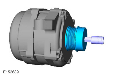
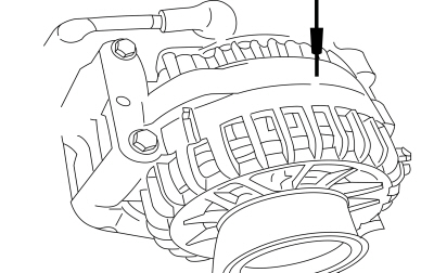 Generator case
.GIF) Click here to access Guided Routine (PCM).
Click here to access Guided Routine (PCM).
System Voltage Low or Battery is Discharged
Refer to Wiring Diagrams Cell 12 for schematic and connector information.
Normal Operation and Fault Conditions
With the engine running, the charging system supplies voltage to the battery and the vehicle electrical system through the high current BJB and battery B+ cable. The PCM monitors this B+ voltage through PCM VPWR or INJPWM circuits. If the charging system voltage drops 1.5 volts or more below the generator voltage desired (GENVDSD), the DTC sets and the charging system MIL illuminates after 30 seconds.
Diagnostic Trouble Code (DTC) Fault Trigger Conditions
| DTC | Description | Fault Trigger Conditions |
|---|---|---|
| P0562 | System Voltage Low | If voltage drops 1.5 volts or more below the generator voltage desired (calculated by the PCM ), this DTC sets after 30 seconds. |
| P065B | Generator Control Circuit Range/Performance | This DTC sets when the generator reports an internal regulator failure. |
| P065C | Generator Mechanical Performance | This DTC sets when the generator reports an internal mechanical failure. |
Possible Sources
- Battery
- Fuses or fusible links
- Generator
- PCM
- Wiring, terminals or connectors
Visual Inspection and Diagnostic Pre-checks
- Inspect the FEAD system. REFER to 303-05.
- Inspect for abnormal ignition-off current drain(s).
- Inspect the battery.
- Inspect the high current BJB for loose, damaged or corroded connections.
PINPOINT TEST B: SYSTEM VOLTAGE LOW OR BATTERY IS DISCHARGED
| NOTE: Make sure battery voltage is greater than 12.2 volts prior to and during this pinpoint test. | ||||||||||||||||||||||||||||
| NOTE: Do not have a battery charger attached during vehicle testing. | ||||||||||||||||||||||||||||
| B1 PERFORM INSPECTION AND VERIFICATION | ||||||||||||||||||||||||||||
Was an obvious cause for an observed or reported concern found?
|
||||||||||||||||||||||||||||
| B2 RETRIEVE DIAGNOSTIC TROUBLE CODES (DTCS) | ||||||||||||||||||||||||||||
Is DTC P065B, P065C, U012D or U042E present?
|
||||||||||||||||||||||||||||
| B3 CHECK THE GENERATOR CONNECTIONS | ||||||||||||||||||||||||||||
Is the voltage within 0.5 volt of the recorded battery voltage?
|
||||||||||||||||||||||||||||
| B4 CHECK THE VOLTAGE DROP IN THE GENERATOR B+ CIRCUIT | ||||||||||||||||||||||||||||
Is the voltage drop less than 0.5 volt?
|
||||||||||||||||||||||||||||
| B5 CHECK THE VOLTAGE DROP IN THE VEHICLE GROUNDS | ||||||||||||||||||||||||||||
Is the voltage drop less than 0.5 volt?
|
||||||||||||||||||||||||||||
| B6 MONITOR THE GENERATOR VOLTAGE DESIRED (GENVDSD) PID (PARAMETER IDENTIFICATION) WHILE COMMANDED | ||||||||||||||||||||||||||||
Is the recorded battery voltage within ±0.5 volt of the PID ?
|
||||||||||||||||||||||||||||
| B7 COMPARE THE SUPPLY VOLTAGE (VPWR) PID (PARAMETER IDENTIFICATION) TO BATTERY VOLTAGE | ||||||||||||||||||||||||||||
Does the PID accurately display battery voltage within ±0.5 volt of the recorded battery voltage?
|
||||||||||||||||||||||||||||
| B8 CHECK PCM (POWERTRAIN CONTROL MODULE) VOLTAGE SUPPLY CIRCUITS | ||||||||||||||||||||||||||||
Are the voltages within 0.5 volt of the recorded battery voltage?
|
||||||||||||||||||||||||||||
| B9 CHECK PCM (POWERTRAIN CONTROL MODULE) GROUND FOR HIGH RESISTANCE | ||||||||||||||||||||||||||||
Does the PID read within ±0.5 volt of battery voltage with accessory loads on and off?
|
||||||||||||||||||||||||||||
| B10 MONITOR THE SUPPLY VOLTAGE (VPWR) PID (PARAMETER IDENTIFICATION) | ||||||||||||||||||||||||||||
Does the PID stay within 0.5 volt of the recorded battery voltage when the engine Revolutions Per Minute (RPM) are increased?
|
||||||||||||||||||||||||||||
| B11 CHECK GENERATOR CLUTCH OPERATION | ||||||||||||||||||||||||||||
Is the generator clutch OK?
|
||||||||||||||||||||||||||||
| B12 CHECK FOR CORRECT PCM (POWERTRAIN CONTROL MODULE) OPERATION | ||||||||||||||||||||||||||||
Is the concern still present?
|
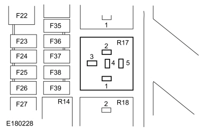 BJB
PCM Relay pin 3
BJB
PCM Relay pin 3

Generator Noise or Mechanical Performance
Normal Operation and Fault Conditions
The generator is belt-driven by the engine FEAD system. There are several sources of generator noise which include bearing noise, electrical fault noise, generator or belt pulley misalignment. A generator with certain types of diode or stator failures can also produce an audible noise.
DTC Fault Trigger Conditions
| DTC | Description | Fault Trigger Conditions |
|---|---|---|
| P065C | Generator Mechanical Performance | This DTC sets when the generator reports an internal mechanical failure. |
Possible Sources
- FEAD belt
- Loose bolts/brackets
- Generator/pulleys
Visual Inspection and Diagnostic Pre-checks
- Inspect the FEAD belt.
- Inspect for loose bolts/brackets.
- Inspect the generator/pulley.
PINPOINT TEST C: GENERATOR NOISE OR MECHANICAL PERFORMANCE
| C1 CHECK FOR ACCESSORY DRIVE BELT NOISE AND LOOSE MOUNTING BRACKETS | ||||
Is the accessory drive OK?
|
||||
| C2 CHECK THE GENERATOR MOUNTING | ||||
Is the generator mounted correctly?
|
||||
| C3 CHECK THE GENERATOR FOR NOISE | ||||
Is the generator the noise source?
|
||||
| C4 CHECK GENERATOR CLUTCH OPERATION | ||||
Is the generator clutch OK?
|
Radio Interference
Refer to Wiring Diagrams Cell 12 for schematic and connector information.
Normal Operation and Fault Conditions
The generator radio suppression equipment reduces interference transmitted through the speakers by the vehicle electrical system.
NOTE: If the Original Equipment Manufacturer (OEM) Audio Control Module (ACM) has been replaced with an aftermarket unit, the vehicle may not pass this test. Return the vehicle to Original Equipment Manufacturer (OEM) condition before following this pinpoint test.
NOTE: If the engine is operated at greater than 2,000 Revolutions Per Minute (RPM) momentarily, the generator self-excites. Make sure when the generator is disconnected the engine rpm stays below 2,000 Revolutions Per Minute (RPM). If it rises above 2,000 Revolutions Per Minute (RPM), turn the ignition to the OFF position and start the test over again.
NOTE: Inspect for any aftermarket accessories that have been added to the vehicle. Check the wiring for these accessories and be sure they have not been attached to the generator circuits and are positioned away from the generator wiring.
Possible Sources
- Generator
- In-vehicle entertainment system
- Wiring, terminals or connectors
Visual Inspection and Diagnostic Pre-checks
- Inspect the generator.
- Inspect the in-vehicle entertainment system.
PINPOINT TEST D: RADIO INTERFERENCE
| D1 VERIFY THE GENERATOR IS THE SOURCE OF THE AUDIO SYSTEM INTERFERENCE | ||||
Is the interference present with the generator disconnected?
|
Battery Monitoring Sensor Faults
Refer to Wiring Diagrams Cell 12 for schematic and connector information.
Normal Operation and Fault Conditions
The BCM monitors the battery state of charge using the battery monitoring sensor attached to the negative battery cable. Battery voltage is hardwired to the battery monitoring sensor and data is transferred from the battery monitoring sensor to the BCM via a LIN circuit.
Diagnostic Trouble Code (DTC) Fault Trigger Conditions
| DTC | Description | Fault Trigger Conditions |
|---|---|---|
| B11DB:02 | Battery Monitoring Module "A": General Signal Failure | This DTC sets if the BCM receives corrupted data from the battery monitoring sensor over the LIN . |
| B11DB:08 | Battery Monitoring Module "A": Bus Signal / Message Failure | This DTC sets if the BCM receives corrupted data from the battery monitoring sensor over the LIN . |
| B11DB:09 | Battery Monitoring Module "A": Component Failure | This DTC sets if the BCM detects a fault on the battery monitoring sensor LIN . |
| B11DB:11 | Battery Monitoring Module "A": Circuit Short To Ground | This DTC sets if the BCM detects low voltage on the battery monitoring sensor LIN . |
| B11DB:9A | Battery Monitoring Module "A": Component or System Operating Conditions | This DTC sets if the BCM receives corrupted data from the battery monitoring sensor over the LIN . |
| B1489:11 | Battery Monitoring System (BMS) Sensor Power Circuit Short To Ground | This DTC sets if the BCM receives no data from the battery monitoring sensor over the LIN . |
Possible Sources
- Battery monitoring sensor
- BCM
- Wiring, terminals or connectors
Visual Inspection and Diagnostic Pre-checks
- Inspect the battery monitoring sensor.
- Inspect the battery monitoring sensor connector.
- Inspect the BJB fuse 5 (275A).
PINPOINT TEST E: BATTERY MONITORING SENSOR FAULTS
| NOTE: Make sure battery voltage is greater than 12.2 volts prior to and during this pinpoint test. | ||||||||||||||||
| NOTE: Do not have a battery charger attached during vehicle testing. | ||||||||||||||||
| E1 CHECK ELECTRICAL CONNECTOR CONDITION | ||||||||||||||||
Are all connectors clean and connected properly?
|
||||||||||||||||
| E2 RETRIEVE BCM (BODY CONTROL MODULE) DIAGNOSTIC TROUBLE CODES (DTCS) | ||||||||||||||||
Did the DTC return?
|
||||||||||||||||
| E3 CHECK THE BATTERY MONITORING SENSOR SUPPLY VOLTAGE | ||||||||||||||||
Is the voltage within 0.5 volt of the recorded battery voltage?
|
||||||||||||||||
| E4 CHECK THE BATTERY MONITORING SENSOR LIN (LOCAL INTERCONNECT NETWORK) CIRCUIT FOR A SHORT TO VOLTAGE | ||||||||||||||||
Is the voltage greater than 10 volts?
|
||||||||||||||||
| E5 CHECK THE BATTERY MONITORING SENSOR LIN (LOCAL INTERCONNECT NETWORK) CIRCUIT FOR A SHORT TO GROUND | ||||||||||||||||
Is the resistance greater than 10,000 ohms?
|
||||||||||||||||
| E6 CHECK THE BATTERY MONITORING SENSOR LIN (LOCAL INTERCONNECT NETWORK) CIRCUIT FOR AN OPEN | ||||||||||||||||
Is the resistance less than 3 ohms?
|
||||||||||||||||
| E7 CHECK FOR CORRECT BCM (BODY CONTROL MODULE) OPERATION | ||||||||||||||||
Is the concern still present?
|

DTC U012D, U042E
Refer to Wiring Diagrams Cell 12 for schematic and connector information.
Normal Operation and Fault Conditions
The charging system supplies voltage to the battery and the vehicle electrical system through the battery B+ cable. The PCM monitors the generator output through a LIN communication circuit shared with the automatic grill shutters (AGS). The PCM uses this LIN circuit to communicate the desired voltage setpoint to the generator internal voltage regulator. The generator also uses this to communicate the generator load and error conditions to the PCM .
Diagnostic Trouble Code (DTC) Fault Trigger Conditions
| DTC | Description | Fault Trigger Conditions |
|---|---|---|
| U012D | Lost Communication With Generator Control Module | Sets if the PCM does not detect communication through the LIN circuit. This can be a result of an open or short in the LIN circuit. This DTC also sets if the generator B+ circuit is open. |
| U042E | Invalid Data Received From Generator Control Module | Sets when the PCM receives invalid data from the generator. |
Possible Sources
- Active grille shutters
- Generator
- PCM
- Wiring, terminals or connectors
Visual Inspection and Diagnostic Pre-checks
- Inspect high current BJB for loose, damaged or corroded connections.
- Inspect the BJB fuse 5 (275A).
- Inspect the FEAD belt.
PINPOINT TEST F: DTC U012D, U042E
| NOTE: Make sure battery voltage is greater than 12.2 volts prior to and during this pinpoint test. | ||||||||||||||||
| NOTE: Do not have a battery charger attached during vehicle testing. | ||||||||||||||||
| F1 CHECK VEHICLE FOR PRESENCE OF GRILLE SHUTTERS | ||||||||||||||||
Is the vehicle equipped with grille shutters?
|
||||||||||||||||
| F2 RETRIEVE PCM (POWERTRAIN CONTROL MODULE) DIAGNOSTIC TROUBLE CODES (DTCS) WITH GRILLE SHUTTER ACTUATOR DISCONNECTED | ||||||||||||||||
Is DTC U012D or U042E present?
|
||||||||||||||||
| F3 COMPARE THE GENERATOR B+ CIRCUIT TO BATTERY VOLTAGE | ||||||||||||||||
Is the voltage within 0.5 volt of the recorded battery voltage?
|
||||||||||||||||
| F4 CHECK THE GENERATOR LIN (LOCAL INTERCONNECT NETWORK) CIRCUIT FOR A SHORT TO VOLTAGE | ||||||||||||||||
Is any voltage present?
|
||||||||||||||||
| F5 CHECK THE GENERATOR LIN (LOCAL INTERCONNECT NETWORK) CIRCUIT FOR A SHORT TO GROUND | ||||||||||||||||
Is the resistance greater than 10,000 ohms?
|
||||||||||||||||
| F6 CHECK THE GENERATOR LIN (LOCAL INTERCONNECT NETWORK) CIRCUIT FOR AN OPEN | ||||||||||||||||
Is the resistance less than 3 ohms?
|
||||||||||||||||
| F7 CHECK FOR CORRECT PCM (POWERTRAIN CONTROL MODULE) OPERATION | ||||||||||||||||
Is the concern still present?
|
Generator Current Sensor Faults
Refer to Wiring Diagrams Cell 13 for schematic and connector information.
Normal Operation and Fault Conditions
The generator current sensor is a Hall-effect sensor attached to the generator B+ cable. It is supplied a 5 volt reference and ground from the PCM . The PCM reads the generator current sensor feedback voltage to determine how much current is flowing through the generator B+ cable.
Diagnostic Trouble Code (DTC) Fault Trigger Conditions
| DTC | Description | Fault Trigger Conditions |
|---|---|---|
| P0A5A | Generator Current Sensor Circuit Range/Performance | Sets in the PCM when the PCM does not detect current through the generator current sensor and there are no generator current sensor circuit Diagnostic Trouble Codes (DTCs) set. |
| P0A5B | Generator Current Sensor Circuit Low | Sets in the PCM when the PCM senses lower than expected voltage on the generator current sensor feedback circuit, indicating an open or a short directly to ground. |
| P0A5C | Generator Current Sensor Circuit High | Sets in the PCM when the PCM senses higher than expected voltage on the generator current sensor feedback circuit, indicating a short directly to voltage. |
Possible Sources
- Generator current sensor
- Generator clutch
- PCM
- Wiring, terminals or connectors
Visual Inspection and Diagnostic Pre-checks
- Inspect the generator current sensor.
- Inspect the generator current sensor connector.
PINPOINT TEST G: GENERATOR CURRENT SENSOR FAULTS
| NOTE: Make sure battery voltage is greater than 12.2 volts prior to and during this pinpoint test. | |||||||||||||
| NOTE: Do not have a battery charger attached during vehicle testing. | |||||||||||||
| G1 RETRIEVE DIAGNOSTIC TROUBLE CODES (DTCS) | |||||||||||||
Is DTC P0562 present?
|
|||||||||||||
| G2 CHECK THE GENERATOR CURRENT SENSOR | |||||||||||||
Are any of these conditions found during inspection?
|
|||||||||||||
| G3 CHECK THE GENERATOR CURRENT SENSOR REFERENCE VOLTAGE CIRCUIT FOR AN OPEN | |||||||||||||
Is the voltage between 4.8 and 5.2 volts?
|
|||||||||||||
| G4 CHECK THE GENERATOR CURRENT SENSOR SIGNAL RETURN CIRCUIT FOR AN OPEN | |||||||||||||
Is the voltage between 4.8 and 5.2 volts?
|
|||||||||||||
| G5 CHECK THE GENERATOR CURRENT SENSOR FEEDBACK CIRCUIT FOR A SHORT TO VOLTAGE | |||||||||||||
Is any voltage present?
|
|||||||||||||
| G6 CHECK THE GENERATOR CURRENT SENSOR FEEDBACK CIRCUIT FOR A SHORT TO GROUND | |||||||||||||
Is the resistance greater than 10,000 ohms?
|
|||||||||||||
| G7 CHECK THE GENERATOR CURRENT SENSOR FEEDBACK CIRCUIT FOR A SHORT TO THE SIGNAL RETURN OR VOLTAGE REFERENCE CIRCUIT | |||||||||||||
Are the resistances greater than 10,000 ohms?
|
|||||||||||||
| G8 CHECK THE GENERATOR CURRENT SENSOR FEEDBACK CIRCUIT FOR AN OPEN | |||||||||||||
Is the resistance less than 3 ohms?
|
|||||||||||||
| G9 CHECK THE GENERATOR CURRENT SENSOR CONNECTION | |||||||||||||
Did the DTC return?
|
|||||||||||||
| G10 CHECK FOR CORRECT PCM (POWERTRAIN CONTROL MODULE) OPERATION | |||||||||||||
Is the concern still present?
|
Generator Clutch Component Test
Refer to Wiring Diagrams Cell 12 for schematic and connector information.
Normal Operation and Fault Conditions
The generator clutch allows the generator rotor to continue to rotate when the engine or FEAD
system slows. The clutch should slip freely and smoothly in a
clockwise direction. It should not rotate freely in the counterclockwise
direction. A loose FEAD
belt or a weak or binding tensioner can cause the pulley to overheat.
REFER to: Charging System - 2.0L EcoBoost (184kW/250PS) – MI4 -
System Operation and Component Description (414-00 Charging System -
General Information, Description and Operation).
PINPOINT TEST H: GENERATOR CLUTCH COMPONENT TEST
| H1 INSPECT THE GENERATOR CLUTCH | ||||
Is there evidence of heat damage?
|
||||
| H2 CHECK THE GENERATOR CLUTCH FOR SMOOTH ROTATION | ||||
Does the clutch shaft rotation feel rough or seized?
|
||||
| H3 CHECK FOR REVERSE ROTATION RESISTANCE | ||||
Is there some resistance (a spring feel)?
|
||||
| H4 CHECK FOR REVERSE ROTATION | ||||
Does the clutch shaft rotate freely?
|


Other information:
Lincoln Nautilus 2018-2026 Owners Manual: What Is the Tachometer. What Is the Speedometer. Fuel Gauge
What Is the Tachometer Shows the engine speed. The red line thickens where the engine speed enters the overspeed limiter. What Is the Speedometer Displays the vehicle speed. Fuel Gauge What Is the Fuel Gauge Indicates approximately how much fuel is in the fuel tank. Fuel Gauge Limitations The fuel gauge may not provide an accurate reading when your vehicle is on an incline. Locating the Fuel F..
Lincoln Nautilus 2018-2026 Service Manual: Brake Master Cylinder. Removal and Installation
Removal NOTICE: Do not spill brake fluid on painted or plastic surfaces or damage to the surface may occur. If brake fluid is spilled onto a painted or plastic surface, immediately wash the surface with water. NOTE: Removal steps in this procedure may contain installation details. NOTICE: Before removing the master cylinder, relieve the vacuum in the brake booster or the ..
Categories
- Manuals Home
- 1st Generation Nautilus Owners Manual
- 1st Generation Nautilus Service Manual
- USB Ports
- Switching the Lane Keeping System On and Off. Switching the Lane Keeping System Mode
- Opening the Liftgate
- New on site
- Most important about car
Locating the Pre-Collision Assist Sensors

If a message regarding a blocked sensor or camera appears in the information display, something is obstructing the radar signals or camera images. The radar sensor is behind the fascia cover in the center of the lower grille. With a blocked sensor or camera, the system may not function, or performance may reduce. See Pre-Collision Assist – Information Messages.