Lincoln Nautilus: Perimeter Anti-Theft Alarm / Perimeter Anti-Theft Alarm - System Operation and Component Description. Description and Operation
System Operation
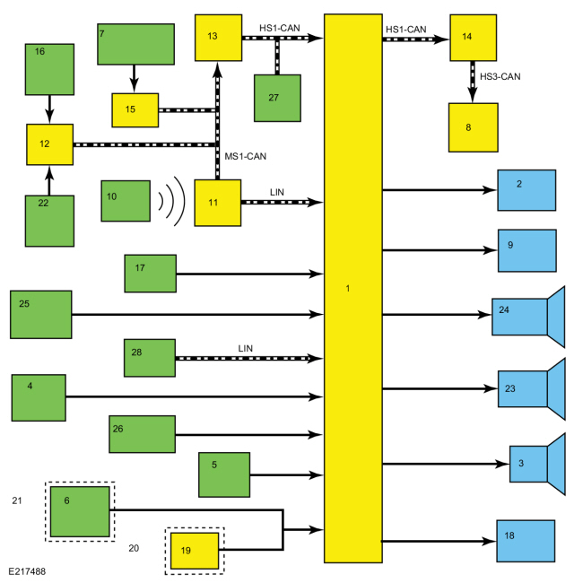
System Diagram
.jpg)
| Item | Description |
|---|---|
| 1 | BCM |
| 2 | Turn Signals |
| 3 | Horn |
| 4 | Door Ajar Switches |
| 5 | Hood Ajar Switch |
| 6 | Liftgate Ajar Switch |
| 7 | Passenger Door Lock Control Switch |
| 8 | IPC |
| 9 | Courtesy Lamps |
| 10 | Passive Key |
| 11 | RTM |
| 12 | DDM |
| 13 | GWM |
| 14 | GWM |
| 15 | PDM |
| 16 | Driver Door Lock Control Switch |
| 17 | Ignition Switch |
| 18 | Door Lock Indicators |
| 19 | RGTM |
| 20 | Manual Liftgate |
| 21 | Power Liftgate |
| 22 | Door Lock Cylinder Switch |
| 23 | Sounder |
| 24 | Anti-Theft Alarm Horn |
| 25 | Rear Door Lock Control Switches |
| 26 | Keyless Entry Keypad |
| 27 | DLC |
| 28 | Intrusion Sensor |
Network Message Chart
IPC Network Input Messages
| Broadcast Message | Originating Module | Message Purpose |
|---|---|---|
| Perimeter alarm chime request | BCM | Used by the IPC to sound the perimeter alarm chime during the 12-second delay. |
BCM Network Input Messages
| Broadcast Message | Originating Module | Message Purpose |
|---|---|---|
| RKE data | RTM | Used by the BCM to arm/disarm the perimeter alarm or to activate/deactivate the panic alarm. |
| Driver door lock switch status | DDM | Used by the BCM to arm the perimeter alarm. |
| Passenger door lock switch status | PDM | Used by the BCM to arm the perimeter alarm. |
Perimeter Alarm
The BCM controls the operation of the perimeter alarm. It monitors inputs from the RKE system, the passive entry system, the power door lock system, the PATS and the ignition status to determine when to arm the perimeter alarm.
The BCM monitors all of the door ajar switches, the liftgate ajar input, the hood ajar switch, the intrusion sensor (if equipped), the CAN and the ignition status to determine when to activate the perimeter alarm. When the BCM detects an input indicating an unauthorized entry into the vehicle, the BCM activates the perimeter alarm by sounding the traffic horn (or the anti-theft alarm horn if equipped with the enhanced security feature) and flashing all of the turn signals and interior courtesy lamps at regular intervals.
The BCM monitors the RKE system, the passive entry system, and the PATS to determine when to disarm the perimeter alarm.
A
switch inhibit feature temporarily disables the door lock control
switches and the liftgate release switch 20 seconds after the vehicle is
electronically locked. For detailed information of the switch inhibit
feature,
Refer to: Handles, Locks, Latches and Entry Systems (501-14 Handles, Locks, Latches and Entry Systems)
.
Additionally, there is a door lock LED
indicator located on each door window sill. The indicators provide
lock/unlock indication for each door. They illuminate when the door is
locked and are off when the door is unlocked. For detailed information
of the door lock LED indicators,
Refer to: Handles, Locks, Latches and Entry Systems (501-14 Handles, Locks, Latches and Entry Systems)
.
Visual
(exterior lamps) and audible feedback (exterior sounder) is also
provided when locking or unlocking the vehicle. For detailed information
of the vehicle locking and unlocking feedback,
Refer to: Handles, Locks, Latches and Entry Systems (501-14 Handles, Locks, Latches and Entry Systems)
.
Arming The Perimeter Alarm
The perimeter alarm is ready to arm any time the ignition is off. The perimeter alarm pre-arms when any of the following occur:
- Pressing the lock button on a RKE transmitter
- Pressing the door lock control switch to the lock position with a front door open, and then closing the door
- Locking the vehicle using the keyless entry keypad
- Locking the vehicle using the passive entry feature
Once the system is pre-armed, there is a 20-second countdown before the perimeter alarm is armed. Each entry point to the vehicle (hood, door and liftgate) is armed separately and must be closed before that entry point begins the 20-second countdown to become armed. If all entry points are closed, the turn signals flash upon locking indicating that all entry points are entering the 20-second countdown.
Perimeter Alarm Activation
The perimeter alarm has a 12-second delay when the driver front door is opened without using a valid programmed RKE transmitter, the keyless entry keypad or a passive key to unlock the vehicle. During the delay, a chime sounds. If the perimeter alarm is not disarmed within the 12-second delay, the alarm activates.
The perimeter alarm activates when:
- The driver front door is opened without first receiving an unlock command from the passive entry feature, the keyless entry keypad or a valid programmed RKE transmitter, and the 12-second delay has expired.
- Any other door, the liftgate or the hood is opened without first receiving an electronic unlock command from the passive entry feature, the keyless entry keypad or a valid programmed RKE transmitter.
- The intrusion sensor detects movement.
- the BCM detects an attempt by a diagnostic scan tool to establish communication on the CAN .
The perimeter alarm only activates 10 times per arming cycle. After that, the alarm does not activate. To enable the perimeter alarm again, disarm the perimeter alarm and then arm it again.
Disarming The Perimeter Alarm
The perimeter alarm disarms when:
- Pressing the unlock button on a door lock control switch within the 20-second pre-arm
- The smart unlock feature activates within the initial 20-second pre-arm
- Pressing the unlock button on a valid programmed RKE transmitter
- Pressing the liftgate release button on a programmed RKE transmitter (this only disarms the liftgate entry point with the rest of the vehicle remaining armed)
- Using a valid programmed key to change the ignition to RUN
- Entering the correct vehicle unlock code on the keyless entry keypad
- Unlocking a front door or opening the liftgate using the passive entry feature
CAN Protection Strategy
When the perimeter alarm is armed, the BCM monitors the CAN . If a scan tool is connected to the DLC , and an attempt is made to establish a session with the BCM , it activates the perimeter alarm.
Every time the BCM detects an unauthorized access (alarm activates), all BCM programming, PID monitoring and self-test sessions are blocked for 10 minutes. At the end of the 10 minute time period, the traffic horn chirps to indicate the 1 minute of opportunity to communicate with the BCM and program keys if none are available.
Refer to: Anti-Theft Key Programming - Scan Tool (419-01B Passive Anti-Theft System (PATS), General Procedures).
Component Description
Door Latch
The door ajar switch, the lock/unlock solenoid and the lock/unlock status input switch are part of the door latch and not serviceable separately.
Hood Ajar Switch
The hood ajar switch is a single pole switch (integrated into the hood latch) that is normally closed when the hood is closed. When the hood is opened, the hood ajar switch opens to indicate an open hood.
The BCM sends a signal to the hood ajar switch and, based on the input, determines if the hood is open or closed.
Intrusion Sensor
The intrusion sensor is powered at all times and is monitored by the BCM . When the perimeter alarm is armed, the intrusion sensor monitors the passenger compartment for movement and inclination changes. If movement or inclination change is detected, it sends a signal to the BCM .
When the intrusion sensor is replaced, the BCM configuration must first be uploaded into a diagnostic scan tool, a new intrusion sensor installed, and then the BCM configuration downloaded back into the BCM for the new intrusion sensor to operate correctly.
Anti-Theft Alarm Horn (if equipped)
If equipped with the enhanced security feature, the anti-theft alarm horn is located behind the right rear quarter trim panel and is controlled by the BCM . When the perimeter alarm activates, the BCM energizes an internal relay to provide voltage to the anti-theft alarm horn.
To verify if the vehicle is equipped with the enhanced security package:
- Make sure the correct VIN was entered on the technician service publication website.
- Hover the mouse cursor over or click on the OASIS tab toward the top left corner of the screen.
- Select HVBoM (Historical Vehicle Bill of Material).
- Enter the anti-theft alarm horn part number of “13832” (do not include quotation marks) in the "Limit to Base" field.
-
Press Enter on the keyboard or click on "View BoM (Build of Material)".
- If the vehicle is equipped with the enhanced security feature, 2 rows appear: one indicating "HORN ASY" in the DESCRIPTION column and the other one indicating "HORN ASY-LOW PITCH" in the DESCRIPTION column.
- If the vehicle is not equipped with the enhanced security feature, only one row appears indicating "HORN ASY-LOW PITCH" in the DESCRIPTION column.
BCM
The BCM controls the operation of the perimeter alarm. Based on input, the BCM arms, disarms, activates or deactivates the perimeter alarm.
The BCM requires PMI when replaced. Additionally, at least 2 keys must be programmed and the parameter reset procedure carried out.
 Perimeter Anti-Theft Alarm - Overview. Description and Operation
Overview
The
perimeter alarm system deters unauthorized entry into the vehicle by
sounding the traffic and/or interior anti-theft alarm horn(s) and
flashing all the turn signals and interior courtesy lamps...
 Perimeter Anti-Theft Alarm. Diagnosis and Testing
DTC Charts
Diagnostics in this manual assume a certain skill level and knowledge of Ford-specific diagnostic practices. REFER to: Diagnostic Methods (100-00 General Information, Description and Operation)...
Other information:
Lincoln Nautilus 2018-2026 Service Manual: Power Fold Seat Motor. Removal and Installation
Removal NOTE: LH rear seat shown, RH rear seat similar. NOTE: Removal steps in this procedure may contain installation details. Remove the rear seat backrest. Refer to: Rear Seat Backrest (501-10B Rear Seats, Removal and Installation)...
Lincoln Nautilus 2018-2026 Service Manual: Front Door Glass Top Run. Removal and Installation
Removal NOTE: LH side shown, RH side similar. NOTE: Removal steps in this procedure may contain installation details. Remove the front door window regulator and motor. Refer to: Front Door Window Regulator and Motor (501-11 Glass, Frames and Mechanisms, Removal and Installation)...
Categories
- Manuals Home
- 1st Generation Nautilus Owners Manual
- 1st Generation Nautilus Service Manual
- Engine Oil Capacity and Specification - 2.0L
- Interior Lamp Function. Adjusting the Instrument Panel Lighting Brightness. Ambient Lighting. Interior Lighting – Troubleshooting
- Opening and Closing the Hood
- New on site
- Most important about car
Opening and Closing the Hood
Opening the Hood