Lincoln Nautilus: Front Drive Halfshafts / Front Halfshaft LH. Removal and Installation
Special Tool(s) / General Equipment
 |
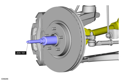
204-161
(T97P-1175-A)
Installer, Halfshaft TKIT-1997-LM2 TKIT-1997-F/FM2 TKIT-1997-FLM2 |
 |
205-D070
(D93P-1175-B)
Remover, Front Wheel Hub |
| Tire Lever | |
Removal
-
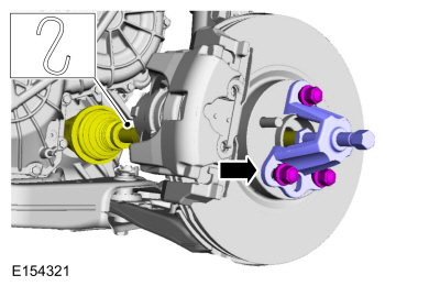
Remove the wheel and tire.
Refer to: Wheel and Tire (204-04A Wheels and Tires, Removal and Installation).
-
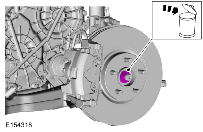
Remove and discard the wheel hub nut.
 |
-
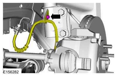
Remove the brake hose bracket bolt and position the brake hose aside.
 |
-
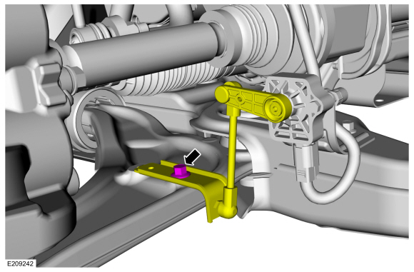
NOTICE: The front suspension height sensor must be disconnected from the lower control arm prior to servicing suspension components or damage to the suspension height sensor and/or the vehicle dynamic suspension system may occur. The sensor will need to be recalibrated after reassembly.
If equipped.
Remove the front height sensor arm bracket bolt and position the front height sensor arm bracket aside.
 |
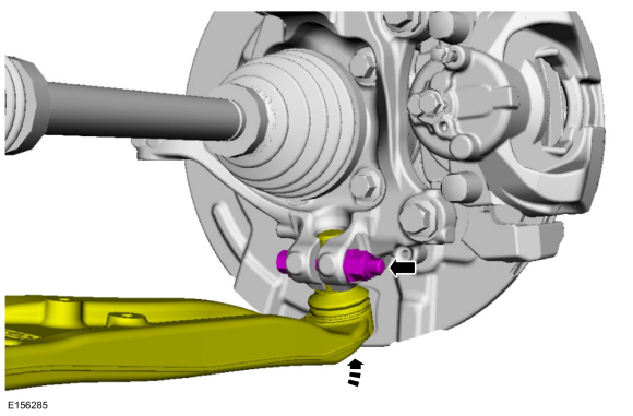
-
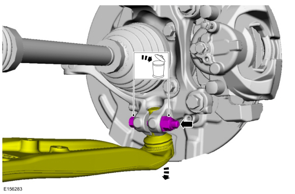
NOTICE: Do not use a prying device or separator fork between the ball joint and the wheel knuckle. Damage to the ball joint or ball joint seal may result. Only use the pry bar by inserting it into the lower arm body opening.
NOTICE: Use care when releasing the lower arm and wheel knuckle into the resting position or damage to the ball joint seal may occur.
Remove and discard the ball joint pinch bolt and nut and separate the ball joint from the wheel knuckle.
 |
-
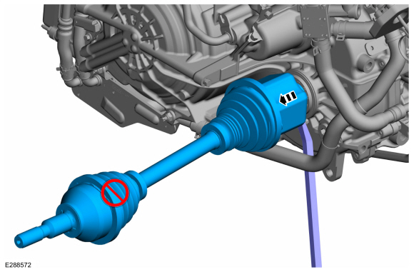
NOTICE: Do not bend the inner joint more than 18 degrees and the outer joint more than 45 degrees. Damage to the shaft will occur.
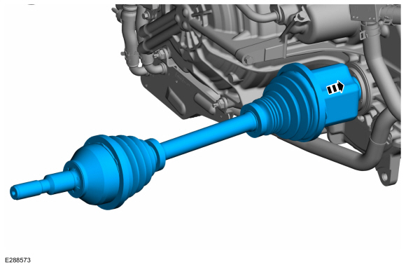
Install the special tool and press the halfshaft from the front wheel bearing and wheel hub.
Use Special Service Tool: 205-D070 (D93P-1175-B) Remover, Front Wheel Hub.
 |
-
Remove the underbody shield.
Refer to: Engine Undershield - FWD (501-02 Front End Body Panels, Removal and Installation).
Refer to: Engine Undershield - 2.7L EcoBoost™ (501-02 Front End Body Panels, Removal and Installation).
-
NOTE: Do not pull on the halfshaft. Pull or pry on the inner CV housing only or damage may occur.
Remove the halfshaft.
Use the General Equipment: Tire Lever
 |
-
Remove and discard the halfshaft retaining circlip.
 |
Installation
-
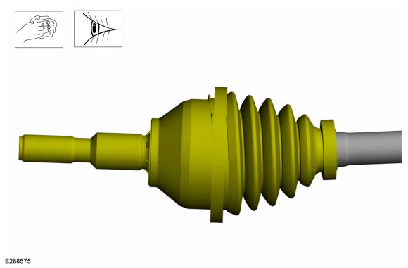
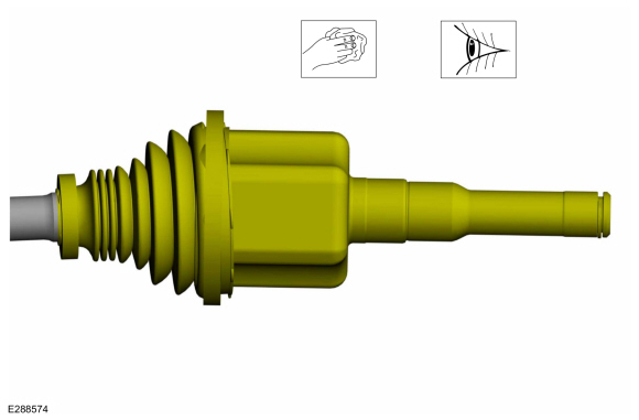
Inspect the outer CV housing.
 |
-
Inspect the inner CV housing.
 |
-
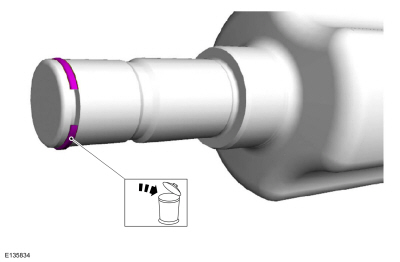
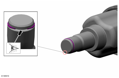
NOTE: Make sure new component is installed.
Install the new inner halfshaft retaining circlip.
 |
-
Replace the halfshaft seal.
Refer to: Halfshaft Seal LH (307-01A Automatic Transmission - 8-Speed Automatic Transmission – 8F35, Removal and Installation).
Refer to: Halfshaft Seal LH (307-01A Automatic Transmission - 8-Speed Automatic Transmission – 8F35, Removal and Installation).
-
NOTE: Insert shaft until circlip is fully seated. When checking if circlip is seated do not pull on CV joints or damage can result.
NOTE: Pull on the inner CV joint to ensure the halfshaft circlip is seated properly.
Insert the halfshaft until the halfshaft retaining clip is fully seated.
 |
-
Pull the halfshaft into the front wheel bearing and wheel hub.
Use Special Service Tool: 204-161 (T97P-1175-A) Installer, Halfshaft.
 |
-
Position the ball joint into the wheel knuckle and install the new ball joint pinch bolt and nut.
Torque: 76 lb.ft (103 Nm)
 |
-
If equipped.
Position the front height sensor arm bracket and install the front height sensor arm bracket bolt.
Torque: 177 lb.in (20 Nm)
|
-
Position the brake hose and install the brake hose bracket bolt.
Torque: 159 lb.in (18 Nm)
|
-
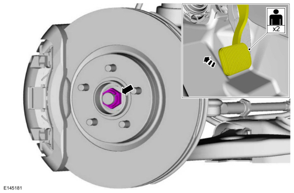
NOTICE: Do not tighten the front wheel hub nut with the vehicle on the ground. The nut must be tightened to specification before the vehicle is lowered onto the wheels. Wheel bearing damage will occur if the wheel bearing is loaded with the weight of the vehicle applied.
NOTICE: Install and tighten the new wheel hub nut to specification in a continuous rotation. Always install a new wheel hub nut after loosening or when not tightened to specification in a continuous rotation or damage to the components may occur.
NOTE: Apply the brake to keep the halfshaft from rotating.
While an assistant applies the brake, install the new wheel hub nut.
Torque: 148 lb.ft (200 Nm)
 |
-
Check the transmission fluid level.
Refer to: Transmission Fluid Level Check (307-01A Automatic Transmission - 8-Speed Automatic Transmission – 8F35, General Procedures).
Refer to: Transmission Fluid Level Check (307-01A Automatic Transmission - 8-Speed Automatic Transmission – 8F35, General Procedures).
-
Install the underbody shield.
Refer to: Engine Undershield - FWD (501-02 Front End Body Panels, Removal and Installation).
Refer to: Engine Undershield - 2.7L EcoBoost™ (501-02 Front End Body Panels, Removal and Installation).
-
Install the wheel and tire.
Refer to: Wheel and Tire (204-04A Wheels and Tires, Removal and Installation).
-
Calibrate the suspension system. Connect the scan tool
and carry out the Ride Height Calibration routine. Follow the scan tool
directions.
 Front Drive Halfshafts. Diagnosis and Testing
Preliminary Inspection
Visually inspect the CV joints, housing, boots, and clamps for obvious signs of mechanical damage.
If an obvious cause for an observed or reported concern is
found, correct the cause (if possible) before proceeding to the next
step
If the cause is not visually evident, verify the symptom and REFER to Symptom Chart: NVH...
 Front Halfshaft RH - FWD. Removal and Installation
Special Tool(s) /
General Equipment
204-161
(T97P-1175-A)
Installer, HalfshaftTKIT-1997-LM2TKIT-1997-F/FM2TKIT-1997-FLM2
205-D070
(D93P-1175-B)
Remover, Front Wheel Hub
Removal
Remove the wheel and tire...
Other information:
Lincoln Nautilus 2018-2026 Service Manual: Fuel Filler Door Assembly. Removal and Installation
Special Tool(s) / General Equipment Flat Headed Screw Driver Knife Removal NOTE: The fuel filler door assembly is damaged during the removal process and requires a new fuel filler door assembly installed. Remove the fuel filler door...
Lincoln Nautilus 2018-2026 Service Manual: Front Halfshaft RH - FWD. Removal and Installation
Special Tool(s) / General Equipment 204-161 (T97P-1175-A) Installer, HalfshaftTKIT-1997-LM2TKIT-1997-F/FM2TKIT-1997-FLM2 205-D070 (D93P-1175-B) Remover, Front Wheel Hub Removal Remove the wheel and tire. Refer to: Wheel and Tire (204-04A Wheels and Tires, Removal and Installation)...
Categories
- Manuals Home
- 1st Generation Nautilus Owners Manual
- 1st Generation Nautilus Service Manual
- Changing the 12V Battery
- Anti-Theft Alarm System Settings. Security – Troubleshooting
- Normal Scheduled Maintenance
- New on site
- Most important about car
Changing a Flat Tire
WARNING: If the tire pressure monitor sensor becomes damaged it may not function.
Note: The use of tire sealant may damage your tire pressure monitoring system and should only be used in roadside emergencies. If you must use a sealant, use the Tire Mobility Kit sealant. Replace the tire pressure monitoring system sensor and valve stem on the wheel by an authorized dealer after use of the sealant.
Note: The tire pressure monitoring system indicator light will illuminate when the spare tire is in use. To restore the full function of the monitoring system, all road wheels equipped with tire pressure monitoring sensors must be mounted on the vehicle.
If you get a flat tire while driving, do not apply the brake hea