Lincoln Nautilus: Front Drive Halfshafts / Front Halfshaft RH - FWD. Removal and Installation
Special Tool(s) / General Equipment
 |
204-161
(T97P-1175-A)
Installer, Halfshaft TKIT-1997-LM2 TKIT-1997-F/FM2 TKIT-1997-FLM2 |
 |
205-D070
(D93P-1175-B)
Remover, Front Wheel Hub |
Removal
-
Remove the wheel and tire.
Refer to: Wheel and Tire (204-04A Wheels and Tires, Removal and Installation).
-
Remove and discard the wheel hub nut.
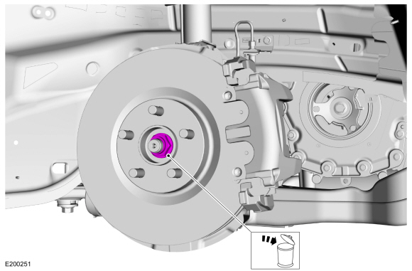 |
-
Remove the brake flexible hose bracket bolt and position the brake flexible hose aside.
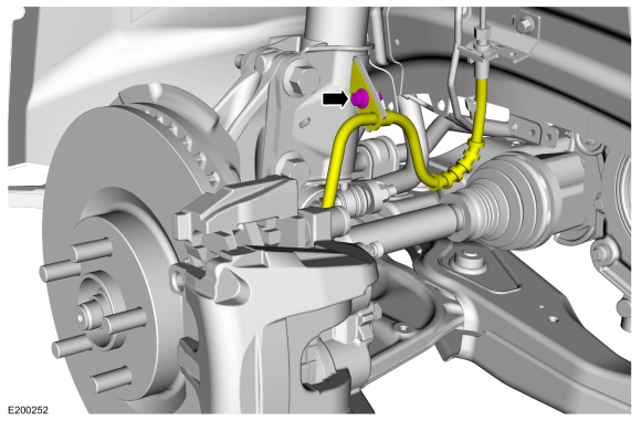 |
-
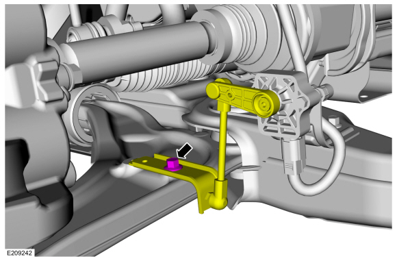
NOTICE: The front suspension height sensor must be disconnected from the lower control arm prior to servicing suspension components or damage to the suspension height sensor and/or the vehicle dynamic suspension system may occur. The sensor will need to be recalibrated after reassembly.
If equipped.
Remove the front height sensor arm bracket bolt and position the front height sensor arm bracket aside.
 |
-
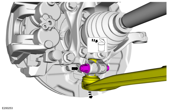
NOTICE: Do not use a prying device or separator fork between the ball joint and the wheel knuckle. Damage to the ball joint or ball joint seal may result. Only use the pry bar by inserting it into the lower arm body opening.
NOTICE: Use care when releasing the lower arm and wheel knuckle into the resting position or damage to the ball joint seal may occur.
Remove and discard the ball joint pinch bolt and nut and separate the ball joint from the wheel knuckle.
 |
-
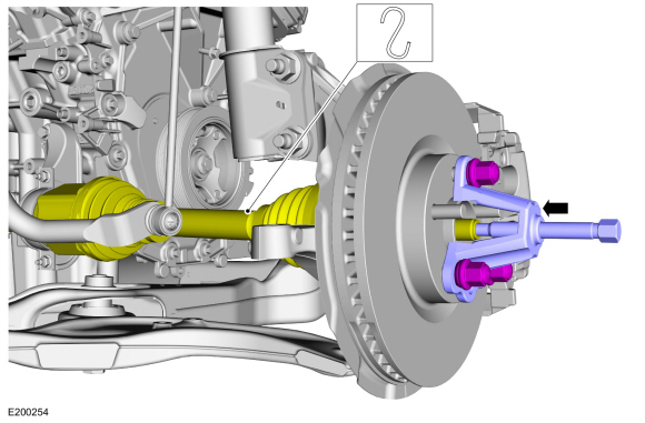
NOTICE: Do not bend the inner joint more than 18 degrees and the outer joint more than 45 degrees. Damage to the shaft will occur.
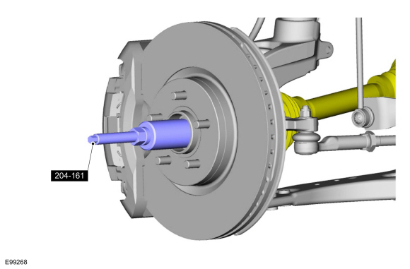
Install the special tool and press the halfshaft from the front wheel bearing and wheel hub.
Use Special Service Tool: 205-D070 (D93P-1175-B) Remover, Front Wheel Hub.
 |
-
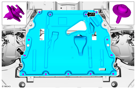
If equipped, remove the underbody shield.
 |
-
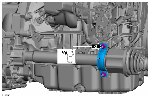
Remove and discard the halfshaft retaining strap and nuts.
 |
-
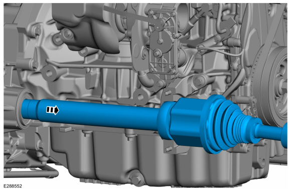
Remove the halfshaft.
 |
Installation
-
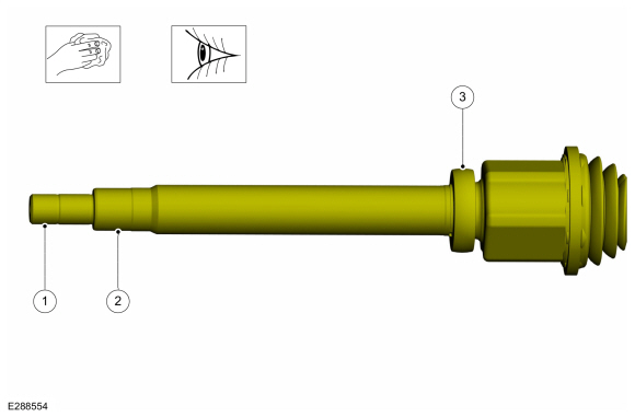
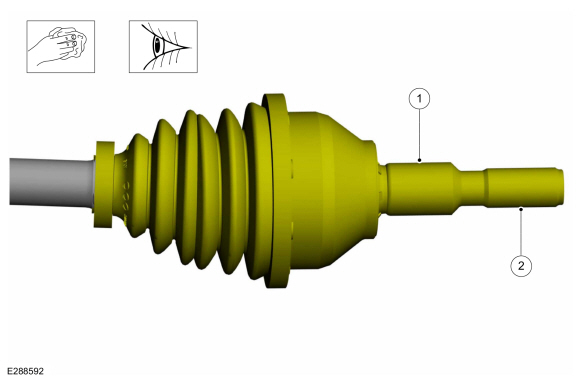
Clean and inspect the inboard end of the halfshaft.
 |
-
Clean and inspect the outboard end of the halfshaft.
 |
-
Install a new halfshaft seal.
Refer to: Halfshaft Seal RH - FWD (307-01A Automatic Transmission - 8-Speed Automatic Transmission – 8F35, Removal and Installation).
Refer to: Halfshaft Seal RH - FWD (307-01B Automatic Transmission - 8-Speed Automatic Transmission – 8F57, Removal and Installation).
-
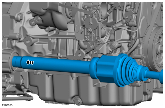
Insert the intermediate shaft until the intermediate
shaft bearing is centered in the concave groove of the intermediate
shaft bearing bracket.
 |
-
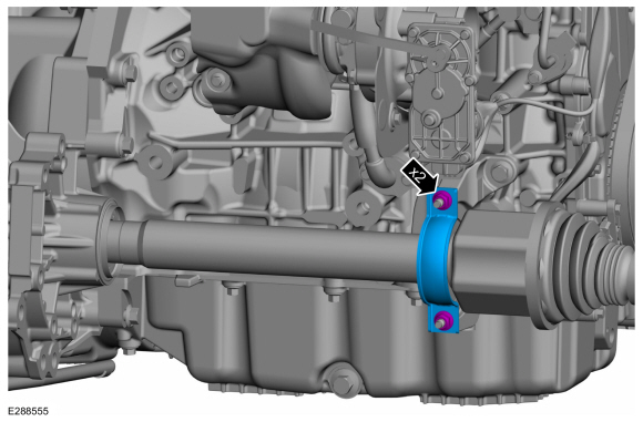
Install the new halfshaft retaining strap and nuts.
Torque:
Stage 1: Tighten lower nut to: 44 lb.in (5 Nm)
Stage 2: Tighten upper nut to: 18 lb.ft (25 Nm)
Stage 3: Tighten lower nut to: 18 lb.ft (25 Nm)
 |
-
-
Insert halfshaft through the wheel bearing.
-
Using the special tool, seat the halfshaft splines in the wheel bearing.
Use Special Service Tool: 204-161 (T97P-1175-A) Installer, Halfshaft.
-
Insert halfshaft through the wheel bearing.
 |
-
Position the ball joint into the wheel knuckle and install the new ball joint pinch bolt and nut.
Torque: 76 lb.ft (103 Nm)
 |
-
If equipped.
Position the front height sensor arm bracket and install the front height sensor arm bracket bolt.
Torque: 177 lb.in (20 Nm)
|
-
Position the brake flexible hose and install the brake flexible hose bracket bolt.
Torque: 159 lb.in (18 Nm)
|
-
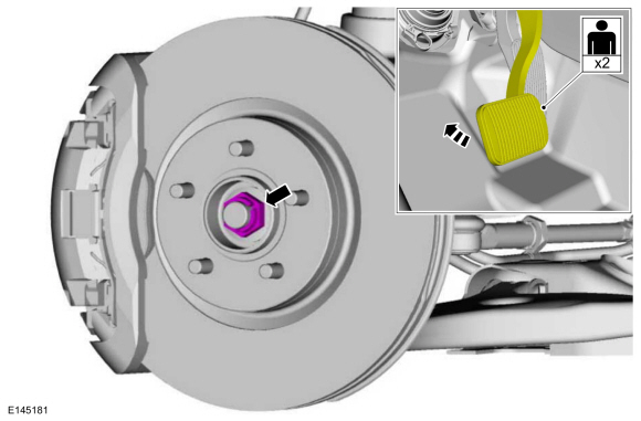
NOTICE: Do not tighten the front wheel hub nut with the vehicle on the ground. The nut must be tightened to specification before the vehicle is lowered onto the wheels. Wheel bearing damage will occur if the wheel bearing is loaded with the weight of the vehicle applied.
NOTICE: Install and tighten the new wheel hub nut to specification in a continuous rotation. Always install a new wheel hub nut after loosening or when not tightened to specification in a continuous rotation or damage to the components may occur.
NOTE: Apply the brake to keep the halfshaft from rotating.
While an assistant applies the brake, install the new wheel hub nut.
Torque: 148 lb.ft (200 Nm)
 |
-
Install the wheel and tire.
Refer to: Wheel and Tire (204-04A Wheels and Tires, Removal and Installation).
-
Check the transmission fluid level.
Refer to: Transmission Fluid Level Check (307-01A Automatic Transmission - 8-Speed Automatic Transmission – 8F35, General Procedures).
Refer to: Transmission Fluid Level Check (307-01B Automatic Transmission - 8-Speed Automatic Transmission – 8F57, General Procedures).
-
If equipped, install the underbody shield and the retainers.
|
-
Calibrate the suspension system. Connect the scan tool
and carry out the Ride Height Calibration routine. Follow the scan tool
directions.
 Front Halfshaft LH. Removal and Installation
Special Tool(s) /
General Equipment
204-161
(T97P-1175-A)
Installer, HalfshaftTKIT-1997-LM2TKIT-1997-F/FM2TKIT-1997-FLM2
205-D070
(D93P-1175-B)
Remover, Front Wheel Hub
Tire Lever
Removal
Remove the wheel and tire...
 Front Halfshaft RH - 2.0L EcoBoost (184kW/250PS) – MI4, All-Wheel Drive (AWD). Removal and Installation
Special Tool(s) /
General Equipment
204-161
(T97P-1175-A)
Installer, HalfshaftTKIT-1997-LM2TKIT-1997-F/FM2TKIT-1997-FLM2
205-D070
(D93P-1175-B)
Remover, Front Wheel Hub
Tire Lever
Removal
Remove the wheel and tire...
Other information:
Lincoln Nautilus 2018-2026 Service Manual: Supplemental Restraint System (SRS) Repowering. General Procedures
Repower WARNING: Incorrect repair techniques or actions can cause an accidental Supplemental Restraint System (SRS) deployment. Never compromise or depart from these instructions. Failure to precisely follow all instructions could result in serious personal injury from an accidental deployment...
Lincoln Nautilus 2018-2026 Service Manual: Passive Anti-Theft System (PATS). Diagnosis and Testing
DTC Charts Diagnostics in this manual assume a certain skill level and knowledge of Ford-specific diagnostic practices. REFER to: Diagnostic Methods (100-00 General Information, Description and Operation). BCM DTC Chart DTC Description Action B10C7:01 Interior Trunk Antenna: General Electrical Failure ..
Categories
- Manuals Home
- 1st Generation Nautilus Owners Manual
- 1st Generation Nautilus Service Manual
- Interior Lamp Function. Adjusting the Instrument Panel Lighting Brightness. Ambient Lighting. Interior Lighting – Troubleshooting
- Massage Seats
- Engine Oil Capacity and Specification - 2.0L
- New on site
- Most important about car
Traction Control
How Does Traction Control Work
If your vehicle begins to slide, the system applies the brakes to individual wheels and, when needed, reduces power at the same time. If the wheels spin when accelerating on slippery or loose surfaces, the system reduces power in order to increase traction.
Switching Traction Control On and Off
WARNING: The stability and traction control light illuminates steadily if the system detects a failure. Make sure you did not manually disable the traction control system using the information display controls or the switch. If the stability control and traction control light is still illuminating steadily, have the system serviced by an authorized dealer immediately. Operating your vehicle with the traction co