Lincoln Nautilus: Instrumentation, Message Center and Warning Chimes / Instrument Panel Cluster (IPC) - System Operation and Component Description. Description and Operation
System Operation
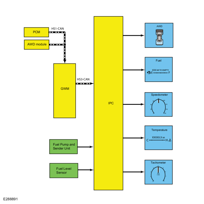
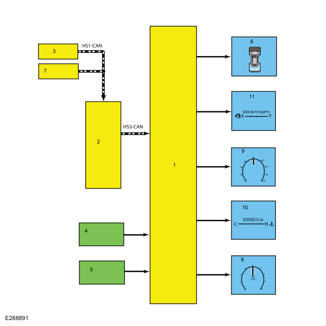
System Diagram - Gauges
| Item | Description |
|---|---|
| 1 | IPC |
| 2 | GWM |
| 3 | PCM |
| 4 | Fuel pump and sender unit |
| 5 | Fuel level sensor |
| 6 | AWD |
| 7 | AWD module |
| 8 | Tachometer |
| 9 | Speedometer |
| 10 | Temperature |
| 11 | Fuel |
Network Message Chart - Gauges
Module Network Input Messages - IPC
| Broadcast Message | Originating Module | Message Purpose |
|---|---|---|
| AWD locking status | AWD module | Input used for the virtual AWD gauge display. |
| Engine coolant temperature data | PCM | Input used for the analog and virtual temperature gauge indication. |
| Engine overheat indication request | PCM | Input used to send the analog and virtual temperature gauge pointer to full hot. |
| Engine rpm data | PCM | Input used for analog and virtual tachometer indication. |
| Ignition status | BCM | Ignition RUN, START and accessory states required for the IPC operating modes and fault reporting. |
| Vehicle speed | PCM | Vehicle speed data used for the virtual AWD gauge display and speedometer indication. |
| Wheel torque | PCM | Input used to control the virtual AWD gauge display. |
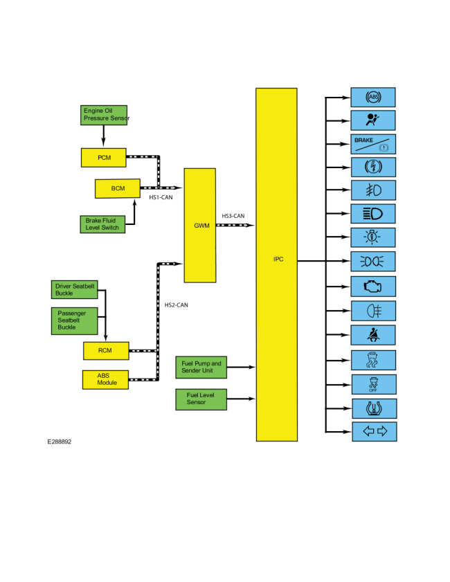
System Diagram - Indicators
.jpg)
| Item | Description |
|---|---|
| 1 | RCM |
| 2 | ABS module |
| 3 | IPC |
| 4 | Brake fluid level switch |
| 5 | Driver seatbelt buckle |
| 6 | PCM |
| 7 | Passenger seatbelt buckle |
| 8 | GWM |
| 9 | BCM |
| 10 | Fuel level sensor |
| 11 | Fuel pump and sender unit |
| 12 | Engine oil pressure sensor |
Network Message Chart - Indicators
Module Network Input Messages - IPC
| Broadcast Message | Originating Module | Message Purpose |
|---|---|---|
| ABS warning indicator request | ABS module | Input used to control the ABS warning indicator. |
| Airbag warning indicator request | RCM | Input used to control the airbag warning indicator. |
| Brake fluid level low message request | BCM | Input from the BCM for low brake fluid level used to control the brake warning indicator. |
| Brake (red) warning indicator request | ABS module | Input from the ABS used to control the brake warning indicator. |
| Driver seatbelt buckle status | RCM | Input used to control the seatbelt warning indicator. |
| Front fog lamp status | BCM | Input used to control the front fog lamp indicator. |
| Headlamp low beam out status | BCM | Input used to control the LED low beam malfunction indicator |
| High beam status | BCM | Input used to control the high beam indicator. |
| Ignition status | BCM | Ignition RUN, START and accessory states required for the IPC operating modes and fault reporting. |
| MIL request | PCM | Input used to control the MIL . |
| Parking brake (red) indicator request | ABS module | Input from the ABS for the parking brake input used to control the brake warning indicator. |
| Parking brake (yellow) indicator request | ABS module | Input from the ABS used to control the electronic parking brake indicator. |
| Parklamp status | BCM | Input used to control the lights on indicator. |
| Rear fog lamp status | BCM | Input used to control the rear fog lamp indicator. |
| Stability-traction control indicator request | ABS module | Input used to control the stability/traction control (sliding car icon) indicator. |
| Stop/start standby indicator | PCM | Input used to control the auto stop/start indicator. |
| Tire pressure warning indicator | BCM | Input used to control the TPMS indicator. |
| Traction control mode | ABS module | Input used to control the stability/traction control disabled (sliding car OFF icon) indicator. |
| Turn indication request | BCM | Input used to control the RH turn, LH turn and hazard indicators. |
Networked Input Messages and Default States
NOTE: Whenever a network message is suspected as missing and confirmed by a missing message DTC (U-code), it is important to look for other symptoms that can also be present in the IPC and throughout the vehicle. Once a DTC sets in the IPC , it is helpful to review the complete message list to determine which other modules also rely on the same message and run the self-test for those modules. If the message is missing from other modules, the same or similar lost communication DTC can also be set in those modules. Confirmation of missing messages common to multiple modules can indicate the originating module is the source of the concern or the communication network may be faulted.
For a list of all the network messages,
Refer to: Communications Network (418-00 Module Communications Network)
.
The IPC uses input messages from other modules to control the gauges, informational indicators, warning indicators and message center message displays over the communication networks. The IPC receives all networked data over the HS-CAN3 .
The vehicle uses 4 or 5 communication networks to transmit the data used by the IPC .
- HS-CAN1
- HS-CAN2
- HS-CAN3
- HS-CAN4 (optional)
- MS-CAN
For overview information,
Refer to: Communications Network (418-00 Module Communications Network)
.
For system operation information,
Refer to: Communications Network (418-00 Module Communications Network)
.
All messaged inputs to the IPC from other networks are received from the GWM over the HS-CAN3 . The GWM , as the name implies, acts as a gateway to convert messages from one of the other 3 or 4 networks to the HS-CAN3 , which is recognized by the IPC .
Network messages can drop out or be missing for a variety of reasons, such as high network traffic on the bus. The IPC incorporates a defined strategy for handling missing network messages based on time. The required time for a network message to be missing differs between the various gauges, indicators and message center displays. The strategy is basically the same for all indication outputs (gauges, indicators or chimes), but differs in the length of time required for the network message to be missing. If a required network message is missing or invalid for less than the programmed length of time, the gauge, indicator or message center display that requires the network message remains at the last commanded state based upon the last network message received. If the messaged input is missing for longer than the programmed length of time, the IPC output (gauge, indicator etc.) reacts according to a pre-defined default action.
For example, if the stability-traction control indicator request network message is missing for less than 5 seconds, and the stability-traction control indicator (sliding car icon) was on, the indicator remains in the on state until the next network message is received. If the network message remains missing or invalid for more than 5 seconds, the IPC sets a U-code DTC and the IPC output becomes a default action for the indicator or gauge. The indicator may default on/off or the gauge may default to the rest position.
Each indicator or gauge utilizes a different default strategy depending on the nature of the indication. Refer to the diagnostic overview descriptions located before each pinpoint test for further descriptions of the default action specific to each indicator or gauge. If the missing messaged input to the IPC returns at any time, the normal function of the gauge, indicator or message center display resumes.
It is very important to understand:
- where the input originates.
- all the information necessary in order for a feature to operate.
- which module(s) receive(s) the input or command message.
- which module controls the output of the feature.
- whether the module that receives the input controls the output of the feature, or whether it outputs a message over the communication network to another module.
Startup-Shutdown
The IPC provides a startup/shutdown sequence also known as a welcome/goodbye strategy. The IPC initiates and follows a progressive strategy providing increasing IPC functionality from IPC wake up to ready to drive status. This sequence begins at RKE unlock or driver door open through the ignition RUN state. During this period, the IPC provides increasing functionality from backlighting or illuminating gauge rings, gauge pointers, illuminating the PRNDL, backlighting of the message center display, displaying a message center splash screen, gauge and LED prove out, gauge sweep and finally normal IPC operation.
MyKey®
The MyKey® feature allows the customer to program a restricted driving mode that is tied to one or more keys known as a MyKey® key. The following features are provided by the IPC when a MyKey® key is being used:
- At the beginning of vehicle start up, as part of the welcome strategy, the message center greets the MyKey® driver with MYKEY ACTIVE DRIVE SAFELY displayed in the message center. If the MyKey® speed limiter feature is turned on, the message center also displays the MyKey® administrator selected top speed setting message; SPEED LIMITED TO XXX KM/H (XX MPH). The MyKey® top speed selections are; 105, 110, 120 or 130 km/h (65, 70, 75, or 80 mph) or to the administrator desired setpoint.
- The IPC provides a periodic Belt-Minder® warning chime until the driver and passenger seatbelts are buckled. When the Belt-Minder® is issued, the ACM is muted and the message center displays BUCKLE UP TO UNMUTE AUDIO.
- If the MyKey® speed limiter feature is turned on and the vehicle speed approaches the selected top speed (110, 120 or 130 km/h [70, 75, or 80 mph]), the message center displays NEAR VEHICLE TOP SPEED along with a chime.
- If the MyKey® speed limiter feature is turned on and the vehicle speed reaches the selected top speed (105, 110, 120 or 130 km/h [65, 70, 75, or 80 mph]), the message center displays TOP SPEED MYKEY SETTING along with a chime.
- If the speed warning is selected at one of the preset values (75 and 90 km/h [45 and 55 mph]) and the vehicle approaches the preset speed, the message center displays CHECK SPEED DRIVE SAFELY along with a chime.
- At approximately 1/8 tank of remaining fuel, the IPC illuminates the low fuel message center indicator and the message center displays FUEL LEVEL LOW along with a chime.
- Traction control, Emergency 911 Assist® feature and the Do Not Disturb feature can be set to always on or user selectable in the MyKey® menu.
- If the traction control always on feature is turned on and the MyKey® driver attempts to disable the traction control, the message center displays ADVANCETRAC ON MYKEY SETTING.
- MyKey® miles driven by the MyKey® user can be found in the information display.
- The number of MyKey® programmed and administrator keys can be found in the MyKey® menu.
- The parking aid, Blind Spot Monitoring System/Cross Traffic Alert (BLIS®/CTA), lane departure alert and collision avoidance warning menus are disabled in the message center to force these features always on.
When an administrator key is in use, the IPC provides:
- a menu in the message center guiding the user to create a MyKey®. When the maximum MyKey® limit is reached, the MyKey® creation menu is no longer available.
-
a menu in the message center with options for setting 6 MyKey® features:
- MyKey® speed limiter.
- MyKey® pre-selected speed warning.
- MyKey® radio volume limiter.
- traction control always on or user selectable.
- emergency 911 assist feature always on or user selectable.
- do not disturb feature always on or user selectable.
- a menu in the message center with the option to clear all MyKey® programmed keys at once.
- MyKey® mileage driven by the MyKey® user can be found in system check function of the message center.
- the number of MyKey® programmed keys and administrator keys can be found in the system check function of the message center.
For information on the MyKey® features, refer to the Owner's Literature.
Configuration
The IPC
contains items that are configurable. Some of the configurable items
(configurable parameters) are customer preference items, which can be
set with a diagnostic scan tool. The remaining configurable items can
only be set through the vehicle configuration parameters.
Refer to: Module Configuration (418-01 Module Configuration)
.
Prove-Out
The IPC carries out a display prove-out to verify the gauges function and all module controlled warning indicator lamps and monitored systems are functioning correctly within the IPC . Upon initiation of the prove-out, the gauges sweep from one stop to the other then return to the normal indication state based on the input received. The IPC also provides a timed prove-out of some indicators while other indicators illuminate upon engine start up or have no prove-out. When the ignition is cycled on, the indicators illuminate to prove-out according to the following table:
| Indicator | Indicator Type | Prove-Out Duration |
|---|---|---|
| Airbag | Warning | 6 seconds |
| ABS | Warning | 3 seconds |
| Brake | Warning | 3 seconds |
| Electronic park brake | Informational | 3 seconds |
| High beam | Informational | None |
| LED low beam malfunction | Informational | 3 seconds |
| Lights on | Informational | None |
| MIL | Informational | Engine start up |
| Seatbelt | Informational | 65 seconds if the seatbelt is unbuckled, turns off when the seatbelt is buckled |
| Stability-traction control (sliding car icon) | Warning | 3 seconds |
| Stability-traction control disabled (sliding car OFF icon) | Informational | 3 seconds |
| TPMS | Warning | 3 seconds |
| Turn indicators | Informational | None |
Dealer Test Mode
NOTE: The table lists the displays as they appear when navigating using the down arrow button.
To enter the IPC engineering test mode or dealer test mode, begin with the ignition OFF. Press and hold the LH steering wheel switch OK button. Place the ignition ON and continue to hold the LH steering wheel switch OK button for 5-8 seconds until the display indicates an “ET” RTT indicator near the Odometer. If there are any warnings displayed, then quickly press and release the OK button to individually clear each warning, until “Engineering Test Mode” is displayed. Press the OK button to navigate through each of the display windows. Each OK button press advances the viewing window to the next set of items. To exit the IPC dealer test mode, press and hold the OK button for 5-8 seconds or place the ignition in OFF.
| IPC Display | Description |
|---|---|
|
Initial entry display into the dealer test mode. |
|
Carries out the gauge sweep of the analog gauges. When the sweep (zero to maximum then return to zero) is complete, the actual data is displayed. |
|
Illuminates all cluster microprocessor controlled LED telltales or indicators. Also displays a color palette of boxes below the title. |
|
Displays the IPC part number information. |
|
|
|
Displays all of the Diagnostic Trouble Codes (DTCs) set (history and current Diagnostic Trouble Codes [DTCs]). An X in the HIST or CURR column means the DTC is active. Three Diagnostic Trouble Codes (DTCs) display on each screen. If more Diagnostic Trouble Codes (DTCs) are present, there will be additional screens listing them. If there are no Diagnostic Trouble Codes (DTCs) in history or current, the display will only be the title row. |
|
|
|
Displays the instant fuel level and filtered fuel level in percent. This is used for a single sender fuel level input. |
|
Displays the instant fuel level and filtered fuel level in percent. This is used for the fuel pump assembly input on a dual sender fuel tank configuration. |
|
Displays the instant fuel level and filtered fuel level in percent. This is used for the fuel level sensor input on a dual sender fuel tank configuration. |
|
Displays the values used for calculating the DTE function. |
|
Displays the running average fuel economy. The values are derived from the DTE function. |
|
Displays the key ON initialization, key OFF reference, and zero speed reference fuel level values in fuel level for a single sender fuel level input. |
|
Displays the key ON initialization, key OFF reference, and zero speed reference fuel level values in fuel level for the fuel pump assembly input on a dual sender fuel tank configuration. |
|
Displays the key ON initialization, key OFF reference, and zero speed reference fuel level values in fuel level for the fuel level sensor input on a dual sender fuel tank configuration. |
|
Displays the digital representation of the coolant temperature gauge indication in degrees Celsius. |
|
Displays the values from the odometer count signal and the trip A statistics. |
|
Displays the values from the odometer count signal and the trip B statistics. |
|
Displays the values of the fuel flow display signal from the PCM and the approximate fuel used for the trip stats A. |
|
Displays the values of the fuel flow display signal from the PCM and the approximate fuel used for the trip stats B. |
|
|
|
|
|
|
|
|
|
Repeats the test display cycle. |
Gauges
AWD Gauge
The AWD gauge displays the level of power applied to each wheel. The AWD system is almost always active, it is transferring torque whenever the vehicle is accelerating, boosting output when wheels are slipping and shutting off on the highway to save fuel. The IPC uses the following messaged inputs to determine the AWD gauge display:
- Wheel torque data
- AWD locking status
- Vehicle speed
As power is applied to the wheels, the area directly in front (front wheels) or rear (rear wheels) of each displayed wheel begins to fill in. The lowest power displayed is the closest to the wheel. As the amount of power sent to the wheels increases, the area fills in either forward (front wheels) or rearward (rear wheels) of the wheels.
The IPC receives the AWD data and the vehicle speed messages from the GWM over the HS-CAN3 . The GWM receives the AWD data from the AWD module and the vehicle speed messages from the PCM over the HS-CAN1 .
Fuel Gauge
The IPC sends a reference voltage to the fuel level sender(s). As the fuel level changes, a float actuates the variable resistor fuel level sender, raising or lowering the fuel level signal voltage. The IPC monitors the changes in voltage from both senders and commands the fuel gauge with a corresponding movement of the pointer.
After a fuel fill up, the time for the fuel gauge to move from empty (E) to full (F) ranges from 2 seconds to 55 minutes depending on which operating mode the fuel gauge is in.
The IPC uses 4 different operating modes to calculate the fuel level:
- Anti-slosh (default mode)
- Key OFF fueling
- Key ON fueling
- Recovery
The default fuel gauge mode is called the anti-slosh mode. To prevent fuel gauge changes from fuel slosh (gauge instability due to changes in fuel sensor readings caused by fuel moving around in the tank), the fuel gauge takes approximately 40 minutes to go from empty (E) to full (F).
The key OFF fueling mode (2 seconds to read empty [E] to full [F]) requires 3 conditions to be met:
- The ignition must be in the OFF mode when refueling the vehicle.
- At least 6% of the vehicle's fuel capacity must be added to the fuel tank.
- The IPC must receive a valid ignition ON fuel sensor reading within one second of the ignition being put into the RUN mode. The key ON sample readings are considered valid if the fuel sensor reading is between 10 ohms ± 2 ohms and 180 ohms ± 4 ohms.
If these conditions are not met, the fuel gauge stays in the anti-slosh mode, which results in a slow to read full (F) event.
The key ON fueling mode (approximately 60 seconds to read empty [E] to full [F]) requires the following conditions be met:
- The transmission is in PARK (P) or NEUTRAL (N).
- The ignition is in the RUN mode.
- At least 6% of the vehicle's fuel capacity must be added to the fuel tank
In key ON fueling mode, a 30-second timer activates after the transmission is put into the PARK (P) or NEUTRAL (N) position. When the 30-second time has elapsed and at least 9% of the vehicle's fuel capacity has been added, the fuel gauge response time is 60 seconds to read from empty (E) to full (F). When the transmission is shifted out of PARK (P) or NEUTRAL (N), the fuel gauge strategy reverts to the anti-slosh mode. The key ON fueling mode prevents slow to read full events from happening if the customer refuels the vehicle with the ignition in the RUN mode.
Recovery mode is incorporated into the IPC strategy to recover from a missing fuel level input after a refueling event. Missing fuel level inputs result from intermittent opens in the fuel sensor or its circuits. Recovery mode (empty [E] to full [F] approximately 17 minutes) is initiated when the following 2 conditions are met:
- The IPC is in the anti-slosh (default) mode.
- The actual fuel level in the tank is 5% different from what is being displayed by the fuel gauge.
Speedometer
The IPC receives the vehicle speed message from the GWM over the HS-CAN3 . The GWM receives the vehicle speed message from the PCM over the HS-CAN1 .
The PCM receives the wheel speed data from the GWM over the HS-CAN1 . The GWM receives the wheel speed data from the ABS module over the HS-CAN2 . The PCM uses tire size stored in the vehicle configuration file along with wheel speed inputs to generate a vehicle speed signal.
The IPC provides a tolerance that allows the speed indication to display between 3% below and 7% above the actual vehicle speed. This means that with an actual vehicle speed of 97 km/h (60 mph), the speedometer can indicate between 94-103 km/h (58-64 mph). Incorrect axle ratio, tire size or tire size configuration could potentially affect the speedometer accuracy.
Tachometer
The IPC receives the engine rpm data message from the GWM over the HS-CAN3 . The GWM receives the engine rpm data message from the PCM over the HS-CAN1 .
Temperature Gauge
The IPC uses 2 messages to control the temperature gauge. The first is the engine coolant temperature data, which provides the current engine temperature input to the PCM . The second message is the engine overheat indication request, which is sent by the PCM to the IPC when an overheating condition exists. When the IPC receives the engine overheat indication request message, the IPC sends the temperature gauge to full hot and turns on the over-temperature warning indicator.
The IPC receives the engine coolant temperature data and the engine overheat indication from the GWM over the HS-CAN3 . The GWM receives the engine coolant temperature data and the engine overheat indication request messages from the PCM over the HS-CAN1 .
Indicators
ABS Warning Indicator
The IPC receives the ABS warning indicator request message from the GWM over the HS-CAN3 . The GWM receives the ABS warning indicator request message from the ABS module over the HS-CAN2 . If a fault condition exists in the ABS , the ABS module sends the ABS warning indicator request message to either flash or illuminate the ABS warning indicator.
Refer to ABS /Brake/Stability-Traction Control System Indication description for information on the conditions when the ABS warning indicator is turned on.
ABS /Brake/Stability-Traction Control System Indication
The brake/stability-traction control system indication is controlled almost entirely by the ABS module. The ABS module can illuminate multiple indicators for various fault conditions. The following table provides a summary of the basic fault conditions and the indicators that are illuminated for each condition.
NOTE: Refer to the Normal Operation and Fault Condition description before each brake/stability-traction control system indicator Pinpoint Test (PPT) for the IPC default action for network/missing message conditions.
| Event/Fault Condition | ABS Warning Indicator Status | Brake Warning Indicator Status | Electronic Park Brake Fault Indicator Status | Stability-Traction Control Indicator Status | Stability-Traction Control Disabled Indicator Status |
|---|---|---|---|---|---|
| Parking brake applied | Off |
|
Off | Off | Off |
| Low brake fluid level or brake fluid level input concern | Off | On | Off | Off | Off |
| Stability-traction control event | Off | Off | Off | Flashing | Off |
| Stability-traction control disabled by driver | Off | Off | Off | Off | On |
| Single wheel speed sensor faults | On | On | Off | On | On |
| 2 wheel speed sensor faults on the same axle or 3 wheel speed sensor faults | On | Flashing or on | On | On | On |
| HCU valve fault | On | On | Off | On | On |
| ABS module fault | On | Flashing or on | On | On | On |
| HCU pressure sensor fault (master cylinder pressure input) | Off | On | Off | On | On |
| ABS battery voltage faults | On | Flashing or on | On | On | On |
| ABS pump motor fault | On | On | Off | On | On |
| ABS low brake booster vacuum or vacuum sensor fault | Off | On | Off | Off | Off |
| Steering wheel angle sensor center not found fault | Off | On | Off | On | On |
| ABS to CAN total failure |
|
Off | Off | On | On |
| Thermal shutdown to brake over-temperature condition | Off | Off | Off | Off | Off |
| Parking brake switch fault | Off | Flashing | On | Off | Off |
| Configuration mismatch | Off | Off | Off | Off | Off |
| Vehicle Identification Number (VIN) mismatch | On | On | Off | On | On |
| ACC and ABS both active | Off | Off | Off | Flashing | Off |
Airbag Warning Indicator
The IPC receives the airbag warning indicator request from the GWM over the HS-CAN3 . The GWM receives the airbag warning indicator request from the RCM over the HS-CAN2 . If a SRS concern is detected, the RCM sets a DTC and the IPC illuminates the airbag warning indicator.
Brake Warning Indicator
The brake warning indicator informs the driver the brake fluid level is low, there is a failure in the base brake system or the electronic park brake is applied. The IPC uses 3 messaged inputs to control the brake warning indicator.
- Brake (red) warning indicator request
- Brake fluid level low message request
- Parking brake (red) indicator request
The IPC receives the brake (red) warning indicator request, the brake fluid level low message request and the parking brake (red) indicator request messages from the GWM over the HS-CAN3 .
The GWM receives the brake (red) warning indicator request and the parking brake (red) indicator request from the ABS module over the HS-CAN2 .
The GWM receives the brake fluid level low message request from the BCM over the HS-CAN2 .
Refer to ABS /Brake/Stability-Traction Control System Indication description for information on the conditions when the brake warning indicator is turned on.
Electronic Park Brake Indicator
The electronic park brake indicator indicates a fault in the electronic park brake system. The IPC receives the parking brake (yellow) indicator request from the GWM over the HS-CAN3 . The GWM receives the parking brake (yellow) indicator request from the ABS module over the HS-CAN2 .
Front Fog Lamp Indicator
The front fog lamp indicator informs the driver that the front fog lamps are on. The IPC receives the front fog lamp status message from the GWM over the HS-CAN3 . The GWM receives the front fog lamp status message from the BCM over the HS-CAN1 .
High Beam Indicator
The high beam indicator informs the driver that the high beams are on. The IPC receives the high beam status message from the GWM over the HS-CAN3 . The GWM receives the high beam status message from the BCM over the HS-CAN1 .
LED Low Beam Malfunction Indicator (If Equipped With LED Headlamps)
The LED informs the driver an LED low beam is not functioning correctly. The IPC receives the headlamp low beam out message from the GWM over the HS-CAN3 . The GWM receives the headlamp low beam out message from the BCM over the HS-CAN1 .
LH / RH Turn Signal/Hazard Indicator
When the multifunction switch is in the LH or RH turn position or if the hazard switch is on, the BCM sends the turn indication request to the GWM over the HS-CAN1 . The GWM sends the turn indication request to the IPC over the HS-CAN3 . Upon receipt of the applicable turn signal on/off message, the IPC flashes the turn signal indicator on and off.
Lights On Indicator
When the parking lamps are turned on, the BCM sends the parklamp status message to the GWM over the HS-CAN1 . The IPC receives the parklamp status message from the GWM over the HS-CAN3 to illuminate the lights on indicator.
MIL
The IPC receives the MIL request from the GWM over the HS-CAN3 . The GWM receives the MIL request from the PCM over the HS-CAN1 .
Rear Fog Lamp Indicator (If Equipped)
The rear fog lamp indicator informs the driver that the rear fog lamp is on. The IPC receives the rear fog lamp status message from the GWM over the HS-CAN3 . The GWM receives the rear fog lamp status message from the BCM over the HS-CAN1 .
Seatbelt Warning Indicator
The RCM monitors the driver seatbelt position through the driver seatbelt buckle switch. The RCM provides the driver seatbelt buckle status message to the GWM over the HS-CAN2 . The GWM provides the driver seatbelt status message to the IPC over the HS-CAN3 to either turn on or turn off the seatbelt warning indicator.
Stability-Traction Control Indicator (Sliding Car Icon)
The stability-traction control indicator (sliding car icon) informs the driver of the current status of the stability and traction control systems. The stability-traction control indicator illuminates when a fault condition exists or when an active traction control or stability control event is occuring. The IPC receives the stability-traction control indicator request message from the GWM over the HS-CAN3 . The GWM receives the stability-traction control indicator request message from the ABS over the HS-CAN2 .
Refer to ABS /Brake/Stability-Traction Control System Indication description for information on the conditions when the stability-traction control indicator (sliding car icon) is turned on.
Stability-Traction Control Disabled Indicator (Sliding Car OFF Icon)
The stability-traction control is configured on/off through the message center. When the driver enables or disables the stability-traction control system, the ABS module sends the traction control mode message to the GWM over the HS-CAN2 . The GWM sends the traction control mode message to the IPC over the HS-CAN3 to illuminate or turn off the stability-traction control disabled indicator (sliding car OFF icon) based upon the system state.
Refer to ABS /Brake/Stability-Traction Control System Indication description for information on the conditions when the stability-traction control disabled indicator (sliding car OFF icon) is turned on.
When a MyKey® administrator has set the AdvanceTrac® feature to always on and a MyKey® programmed key is in use, the stability-traction control system cannot be disabled. The menu selection in the message center used to disable the stability-traction control system does not display when a MyKey® is in use, but remains active for the MyKey® administrator to select the AdvanceTrac® always on feature off. The stability-traction control indicator still functions normally to indicate a stability-traction control system fault and a stability-traction control active event.
TPMS Warning Indicator
The IPC receives the tire pressure warning indicator message from the GWM over the HS-CAN3 . The GWM receives the tire pressure warning indicator message from the BCM over the HS-CAN1 .
If the BCM determines the tire pressure has exceeded the low tire pressure limits, the tire pressure warning indicator request message is sent to the IPC to illuminate the TPMS warning indicator.
If a TPMS monitor or sensor fault condition exists, the BCM sends the tire pressure warning indicator request message to the IPC to flash the TPMS warning indicator. The IPC flashes the TPMS warning indicator for 75 seconds then turns the indicator on solid.
Component Description
Brake Fluid Level Switch
The brake fluid level switch is mounted in the master cylinder reservoir and is hardwired to the BCM through a signal circuit. The brake fluid level switch is grounded through a separate body ground circuit. The BCM provides a reference voltage to the brake fluid level switch. When the brake fluid level is low the switch closes, pulling the reference voltage low. When the brake fluid level is high, the switch opens, sending the reference voltage high on the signal circuit to the BCM .
Fuel Level Sender
The fuel level sender is mounted to the fuel pump and sender uni or the fuel level sensor. The fuel level sender is a dual sweep potentiometer style resistor connected to a float mechanism. The dual sweep design provides a second resistance measurement that reduces the intermittent loss of data due to corrosion between the resistor wires and the sweep arm. As the fuel level changes, the float rises or falls with the fuel level moving the sweep arm across the resistor wires. This movement either increases or decreases the resistance through the unit. The fuel level sensor resistance ranges from 180 ohms ± 4 ohms at empty (E) to 10 ohms ± 2 ohms at full (F). When the fuel level is low, the fuel level sensor resistance is high. When the fuel level is high, the fuel level sensor resistance is low.
Both the fuel pump and sender uni and the fuel level sensor are hardwired to the IPC through separate signal and return circuits. The fuel level return circuits are grounded internally in the IPC . The IPC provides a reference voltage on the fuel level signal circuit. As the fuel level changes, the change in resistance raises or lowers the fuel level signal voltage depending on the resistance of the fuel level sender.
IPC
The IPC provides the driver with a system status and alerts the driver when certain conditions exist in the vehicle. The IPC receives the ignition status from the BCM through the GWM over the HS-CAN3 .
The IPC requires PMI when the IPC is replaced. The IPC lens and mask assembly are replaceable as an assembly.
Oil Pressure Sensor (2.0L and 2.7L Engine)
The oil pressure sensor is hardwired to the PCM through VREF, signal and return circuits. The PCM provides the sensor voltage supply on the VREF circuit and monitors the voltage changes through the signal and return circuits as the oil pressure changes.
Seatbelt Buckle Sensor
The seatbelt buckles contain integrated sensors that are Hall-effect switches, which are hard-wired inuts to the RCM . The seatbelt buckle sensors are serviced as one component with the seatbelt buckle.

 Message Center - Overview. Description and Operation
Overview
The message center is an integral part of the IPC that receives and
acts upon much of the same information that is input and used to
operate the IPC
(gauges, informational indicators, and warning indicators)...
Other information:
Lincoln Nautilus 2018-2026 Service Manual: Door Lock Cylinder. Removal and Installation
Removal Remove the exterior front door handle. Refer to: Exterior Front Door Handle (501-14 Handles, Locks, Latches and Entry Systems, Removal and Installation). Remove the door lock cylinder. Installation To install, reverse the removal procedure...
Lincoln Nautilus 2018-2026 Service Manual: Air Conditioning (A/C) System Leak Test Using Forming Gas. General Procedures
Special Tool(s) / General Equipment Forming Gas Pressure Gauge and Leak Detector Materials Name Specification Forming Gas - Leak detection All vehicles NOTE: Use a Rotunda-approved Forming Gas A/C System Dealership Leak Detection Service Kit that meets SAE J2790...
Categories
- Manuals Home
- 1st Generation Nautilus Owners Manual
- 1st Generation Nautilus Service Manual
- Fuel Quality
- Switching the Lane Keeping System On and Off. Switching the Lane Keeping System Mode
- Replacing the Rear Wiper Blades
- New on site
- Most important about car
Traction Control
How Does Traction Control Work
If your vehicle begins to slide, the system applies the brakes to individual wheels and, when needed, reduces power at the same time. If the wheels spin when accelerating on slippery or loose surfaces, the system reduces power in order to increase traction.
Switching Traction Control On and Off
WARNING: The stability and traction control light illuminates steadily if the system detects a failure. Make sure you did not manually disable the traction control system using the information display controls or the switch. If the stability control and traction control light is still illuminating steadily, have the system serviced by an authorized dealer immediately. Operating your vehicle with the traction co