Lincoln Nautilus: Climate Control System - General Information / Air Conditioning (A/C) Compressor - 2.0L EcoBoost (184kW/250PS) – MI4. Removal and Installation
Removal
NOTICE: If installing a new A/C compressor due to an internal failure of the old unit, carry out the following procedures to remove contamination from the A/C system. Failure to remove contamination from the A/C system, if present, will result in poor A/C performance and/or damage to the new A/C compressor and other components.
- If A/C flushing equipment is available, carry out flushing of the A/C system prior to installing a new A/C compressor.
- If A/C flushing equipment is not available, replace all contaminated components after a new A/C compressor has been installed.
- Install a new Thermostatic Expansion Valve (TXV) as directed by the A/C flushing.
- Install a new receiver drier element as directed by the A/C flushing.
NOTICE: During the removal of components, cap, tape or otherwise appropriately protect all openings to prevent the ingress of dirt or other contamination. Remove protective materials prior to installation.
NOTE: Installation of a new receiver drier element is not required when repairing the A/C system except when there is physical evidence of system contamination from a failed A/C compressor or damage to the receiver drier element.
NOTE: A new A/C compressor may come equipped with an A/C clutch disc and hub, A/C compressor pulley and A/C clutch field coil already installed. If these components are not pre-installed, it will be necessary to transfer these parts from the old A/C compressor to the new compressor prior to installation of the A/C compressor if suitable for reuse.
NOTE: Removal steps in this procedure may contain installation details.
-
Recover the refrigerant. Refer to the appropriate Recovery procedure in Group 412.
-
Remove the A/C compressor belt.
Refer to: Air Conditioning (A/C) Compressor Belt (303-05A Accessory Drive - 2.0L EcoBoost (184kW/250PS) – MI4, Removal and Installation).
-
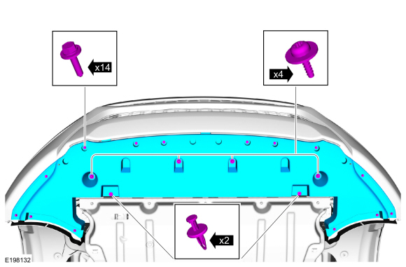
Remove the bolts, the retainers and the front underbody shield.
 |
-
-
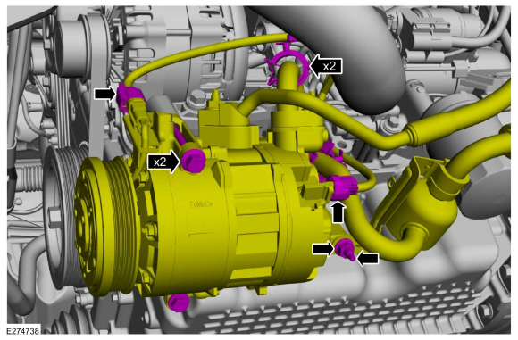
Disconnect the electrical connectors and wiring retainers.
-
Remove the nut and stud.
Torque:
Compressor nut: 18 lb.ft (25 Nm)
-
Remove the bolts and position the A/C compressor aside.
-
Disconnect the electrical connectors and wiring retainers.
 |
-
-
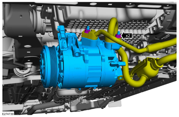
Remove the nuts and disconnect the A/C lines and remove A/C compressor.
Torque: 159 lb.in (18 Nm)
-
Make sure to cover any open ports to prevent debris from entering the system.
-
Remove the nuts and disconnect the A/C lines and remove A/C compressor.
 |
Installation
-
To install, reverse the removal procedure.
-
Tighten the A/C compressor bolts and stud in the sequence shown.
Torque:
1: 18 lb.ft (25 Nm)
2: 80 lb.in (9 Nm)
3: 18 lb.ft (25 Nm)
.jpg) |
-
NOTICE: Only use the specified material to lubricate the seals.
Install and lubricate new O-ring seals. Refer to the appropriate Specifications in Group 412.
-
Lubricate the refrigerant system with the correct amount
of clean PAG oil. Refer to the appropriate Refrigerant Oil Adding
procedure in Group 412.
 Reset the Outside Air Temperature Sensor Learned Values. General Procedures
Configuration
NOTE:
The ambient air temperature sensor is a critical
component for correct Air Conditioning (A/C) and Heating, Ventilation,
and Air Conditioning (HVAC) system operation...
 Air Conditioning (A/C) Compressor Inlet Line - 2.0L EcoBoost (184kW/250PS) – MI4. Removal and Installation
Removal
NOTICE:
During the removal of components, cap, tape or otherwise
appropriately protect all openings to prevent the ingress of dirt or
other contamination...
Other information:
Lincoln Nautilus 2018-2026 Owners Manual: How Do The Side Airbags Work
WARNING: Do not place objects or mount equipment on or near the airbag cover, on the side of the front or rear seatbacks, or in areas that may come into contact with a deploying airbag. Failure to follow these instructions may increase the risk of personal injury in the event of a crash...
Lincoln Nautilus 2018-2026 Service Manual: Front Fog Lamp. Removal and Installation
Removal Remove the front bumper cover. Refer to: Front Bumper Cover (501-19) . Remove the front foglamp. Disconnect the electrical connector. Separate the wire harness retainers.. Remove the foglamp assembly screws...
Categories
- Manuals Home
- 1st Generation Nautilus Owners Manual
- 1st Generation Nautilus Service Manual
- USB Ports
- Programming the Garage Door Opener to Your Garage Door Opener Motor
- Anti-Theft Alarm System Settings. Security – Troubleshooting
- New on site
- Most important about car
Locating the Pre-Collision Assist Sensors

If a message regarding a blocked sensor or camera appears in the information display, something is obstructing the radar signals or camera images. The radar sensor is behind the fascia cover in the center of the lower grille. With a blocked sensor or camera, the system may not function, or performance may reduce. See Pre-Collision Assist – Information Messages.