Lincoln Nautilus: Anti-Lock Brake System (ABS) and Stability Control / Anti-Lock Brake System (ABS) and Stability Control - System Operation and Component Description. Description and Operation
System Operation
System Diagrams
*.sttxt { visibility: hidden; } *.stcallout { visibility: visible; } E368345 1 ABS 2 HCU 3 Hydraulic Pump Motor 4 Hydraulic Valve Solenoids 5 Hydraulic Pressure Sensor 6 GSM 7 Wheel Speed Sensors 8 Brake Vacuum Sensor 9 PSCM 10 SASM 11 RCM 12 SCCM 13 IPMA 14 VDM 15 CCM 16 SECM 17 AWD 18 BCM 19 PCM 20 GWM 21 APIM 22 IPC| Item | Description |
|---|---|
| 1 | ABS module |
| 2 | HCU |
| 3 | Hydraulic pump motor |
| 4 | Hydraulic valve solenoids |
| 5 | Hydraulic pressure sensor |
| 6 | GSM |
| 7 | Wheel speed sensors |
| 8 | Brake vacuum sensor |
| 9 | PSCM |
| 10 | SASM |
| 11 | RCM |
| 12 | SCCM |
| 13 | IPMA |
| 14 | VDM |
| 15 | CCM |
| 16 | SECM |
| 17 | AWD module |
| 18 | BCM |
| 19 | PCM |
| 20 | GWM |
| 21 | APIM |
| 22 | IPC |
SASM
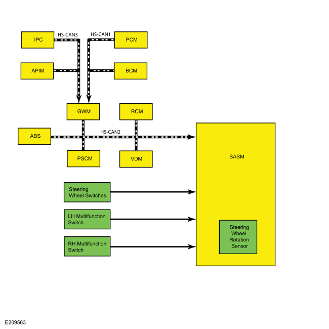

| Item | Description |
|---|---|
| 1 | SASM |
| 2 | Steering wheel rotation sensor |
| 3 | Steering wheel switches |
| 4 | LH multifunction switch |
| 5 | RH multifunction switch |
| 6 | PSCM |
| 7 | ABS module |
| 8 | VDM |
| 9 | RCM |
| 10 | GWM |
| 11 | PCM |
| 12 | BCM |
| 13 | APIM |
| 14 | IPC |
Network Message Charts
ABS Module Network Input Messages
| Broadcast Message | Originating Module | Message Purpose |
|---|---|---|
| Accelerator pedal position | PCM | This message is sent to the GWM and then to the ABS module. The ABS module uses accelerator pedal position information for correct operation of the various ABS and stability control systems. |
| Adaptive cruise control braking deceleration | CCM | This message is sent to the IPMA and then to the ABS module. This message is used to request vehicle deceleration by the ABS module to maintain the distance gap set by the driver for the adaptive cruise control system. |
| Adaptive cruise control brake torque request | CCM | This message is sent to the IPMA and then to the ABS module. This message informs the ABS module of the amount of braking required to maintain the distance gap set by the driver for the adaptive cruise control system. |
| Adaptive cruise control precharge request | CCM | This message is sent to the IPMA and then to the ABS module. This message is used to request precharging of the hydraulic brake system in preparation of a severe braking event. |
| Adaptive cruise control stop mode | CCM | This message is sent to the IPMA and then to the ABS module. This message informs the ABS module of the current adaptive cruise stop mode; stop mode active, stop mode inactive, limit rolling speed, or EPB apply / release warning |
| Adaptive steering data | SASM | Due to the operational nature of the adaptive steering system, an offset exists between what the steering wheel is being turned and what the steering wheel rotation sensor is actually reading. The SASM monitors this offset angle and sends the information to the ABS module for proper stability control system operation. |
| AWD connection status | AWD module | This message is sent to the GWM and then to the ABS module. This message informs the ABS module of the current AWD connection status; connected, disconnected, connecting or disconnecting. |
| AWD locking status | AWD module | This message is sent to the GWM and then to the ABS module. The ABS module uses AWD information for correct operation of the ABS and stability control systems. |
| Ambient air temperature | PCM | This message is sent to the GWM and then to the ABS module. The ABS module uses this information for calculations in determining the operational status of the various stability control systems and features. |
| Auto hold request | APIM | This message is sent to the GWM and then to the ABS module. This message informs the ABS module the driver has pressed the auto hold button. |
| Brake pedal applied | PCM | This message is sent to the GWM and then to the ABS module. This message informs the ABS module the driver has pressed the brake pedal. This message is also used by the ABS module to check the brake pressure sensor located inside the HCU . |
| Clutch pedal data | PCM | This message is sent to the GWM and then to the ABS module. This message informs the ABS module of the current clutch pedal position as a percentage of total travel and if the information is within specifications, faulty or does not exist. |
| Collision mitigation by braking deceleration | CCM | This message is used to request vehicle deceleration by the ABS module for the collision avoidance system. |
| Collision mitigation by braking precharge request | CCM | This message is used to request precharging of the hydraulic brake system in preparation of a severe braking event. |
| Cruise control override status | PCM | This message is sent to the GWM and then to the ABS module. This message informs the ABS module if the PCM overrides the cruise control request. |
| Cruise control mode | PCM | This message is sent to the GWM and then to the ABS module. This message informs the ABS module of the current cruise control mode: not active, keeping speed, accelerating, decelerating, resuming high, resuming low, tap up waiting, tap down waiting. |
| Cruise control status | PCM | This message is sent to the GWM and then to the ABS module. This message informs the ABS module of the current cruise control system status: off, denied, standby or active. |
| Door ajar status | BCM | This message is sent to the GWM and then to the ABS module. This message informs the ABS module of the current door ajar status. There is a separate message for each door. The ABS module resets the parameters used for the ESC and RSC systems when a door is opened. The message is also used for the electronic parking brake automatic release feature. |
| Driven wheel torque output | PCM | This message is sent to the GWM and then to the ABS module. This message informs the ABS module of the current torque output available at the driven wheels. This information is used for the traction control, hill start assist, ESC and RSC feature operation. |
| Driver safety belt buckle | RCM | This message informs the ABS module of the current driver safety belt buckle status, buckled or unbuckled. The ABS module uses this information for the electric parking brake drive away release feature. |
| EPAS external angle request | PSCM | This message informs the ABS module the EPAS gear is in the process of completing a park aid steering request. |
| EPAS status | PSCM | This message informs the ABS module of the current EPAS operation status; inactive or active. |
| Engine disable status | PCM | This message is sent to the GWM and then to the ABS module. This message informs the ABS module the engine is currently disabled or enabled due to the stop-start system. |
| Engine RPM | PCM | This message is sent to the GWM and then to the ABS module. Used to inform the ABS module of the current engine RPM . The ABS module uses this information for EPB drive away release feature, traction control, ESC , RSC and hill start assist operations. |
| Gear lever position | PCM | This message is sent to the GWM and then to the ABS module. This message informs the ABS module of the current selected transmission gear, this is used for the hill start assist system, the ESC system and the RSC system. The hill start assist system operates in forward and reverse gears. The ESC and RSC systems do not operate when the transmission is in REVERSE. The message is also used for the electronic parking brake automatic release feature. |
| Hill start assist request | IPC | This message is sent to the GWM and then to the ABS module. This message informs the ABS module of the current, driver selected mode for the hill start assist system; off, auto or manual. |
| Ignition key type | BCM | This message is sent to the GWM and then to the ABS module. This message informs the ABS module of the current ignition key type; standard or MyKey. The ABS modifies operating parameters if a restricted MyKey is used. |
| Ignition status | BCM | This message is sent to the GWM and then to the ABS module. This message informs the ABS module of the current ignition status; off, accessory, run, start, unknown or invalid. |
| Odometer master value | IPC | This message is sent to the GWM and then to the ABS module. This message informs the ABS module of the current odometer mileage. |
| Park brake active request | GSM | This message informs the ABS module to engage the parking brake for the auto hold feature. |
| PATS start request target command | PCM | This message is first sent to the GWM and then to the ABS module. This message provides the ABS module with the challenge and password for anti-theft vehicle starting. During vehicle starting, the PCM and the ABS module exchange information to make sure the vehicle is being started correctly. |
| PATS start request target status | PCM | This message is first sent to the GWM and then to the ABS module. This message informs the ABS module of the current antitheft start request status; disabled, enabled motive start, enabled non-motive start, disabled reset. |
| Reverse gear active | PCM | This message is sent to the GWM and then to the ABS module. This message informs the ABS module the transmission is in REVERSE gear, this is used for the hill start assist system, the ESC system and the RSC system. The hill start assist system operates in forward and reverse gears. The ESC and RSC systems do not operate when the transmission is in REVERSE. |
| RCM serial number | RCM | The ABS module stores the RCM serial number and verifies the serial number when the vehicle is started or the ignition is set to RUN or ACC. Over time, the ABS module learns the offset of the sensors inside the RCM . When a new serial number is found and the IVD Initialization procedure is carried out using a scan tool, the ABS module resets the offset number learned for ESC and RSC . |
| Steering angle sensor data | PSCM (vehicles without adaptive steering) | Several steering angle messages are sent to the ABS module from the PSCM . These messages include steering angle sensor status, steering wheel angle and steering wheel rotation count. The ABS module uses the steering angle sensor data for ESC and RSC system operation. |
| Steering angle sensor data | SASM (vehicles with adaptive steering) | Several steering angle messages are sent to the ABS module from the SASM . These messages include steering angle sensor status, steering wheel angle, steering wheel rotation count and steering wheel angle offset. The ABS module uses the steering angle sensor data for ESC and RSC system operation. |
| Traction control request | IPC | This message is sent to the GWM and then to the ABS module. This message informs the ABS module the driver has chosen a mode for the traction control feature, ON or OFF. |
| Trailer sway configuration | IPC | This message is sent to the GWM and then to the ABS module. This message informs the ABS module the driver has chosen a mode for the trailer sway feature, ON or OFF. |
| Transmission in reverse | PCM | This message is sent to the GWM and then to the ABS module. This message informs the ABS module when the transmission is in REVERSE, this is used for the hill start assist system, the ESC system and the RSC system. The hill start assist system operates in forward and reverse gears. The ESC and RSC systems do not operate when the transmission is in REVERSE. |
| Vehicle configuration data | BCM | This message is sent to the GWM and then to the ABS module. This message provides the ABS module with the current optional and configured items such as tire size, axle ratio, manual or automatic transaxle, keyless entry and VIN . |
| Vehicle dynamic data display | VDM | Used to inform the ABS module of the current vehicle suspension mode; comfort, normal, sport, faulty, service required, temporarily off, or mode change unavailable. This message is used by the ABS module for traction control and ESC performance. |
| Vehicle lateral acceleration data | RCM | This message provides the ABS module with the current vehicle lateral acceleration and deceleration information and whether or not the information is valid. |
| Vehicle longitudinal acceleration data | RCM | This message provides the ABS module with the current vehicle longitudinal acceleration information and whether or not the information is valid. |
| Vehicle roll rate data | RCM | This message provides the ABS module with the current vehicle roll rate information and whether or not the information is valid. |
| Vehicle yaw data | RCM | This message provides the ABS module with the current vehicle yaw information and whether or not the information is valid. |
SASM Network Input Messages
| Broadcast Message | Originating Module | Message Purpose |
|---|---|---|
| Center stack feature configuration | APIM | This message informs the SASM of the current configuration of the center stack features such as push-button shift, touch screen, FCIM , etc. |
| EPAS status | PSCM | This message informs the SASM of the current EPAS system status; Initialization, Normal Op Limited Assist, Normal Op Full Assist, Shutdown, System Failure, EPAS Failure 2 or EPAS Failure 3. |
| Gear lever position | PCM | This message is sent to the GWM and then to the SASM . This message informs the SASM of the current selected transmission gear. |
| Message center display | IPC | This message is sent to the GWM and then to the SASM . This message informs the SASM of the current message displayed in the message center. |
| Message center feature configuration | IPC | This message is sent to the GWM and then to the SASM . This message informs the SASM of the current message center feature configuration. |
| Odometer master value | IPC | This message is sent to the GWM and then to the SASM . This message informs the SASM of the current odometer mileage. |
| Power pack status | PCM | This message is sent to the GWM and then to the SASM . This message informs the SASM of the current status of the engine system; Off - Torque Not Available, On - Torque Not Available, On - Torque Available or Start In Progress. |
| Restraint impact event status | RCM | This message informs the SASM the vehicle has experienced an impact event and the severity of the impact event. |
| Steering angle off-set | ABS module | The ABS module calculates a steering wheel angel off-set based on information from the wheel speed sensors, stability control sensors and the steering angle information. This information is used by the SASM for self monitoring purposes. |
| Steering column torque | PSCM | This information is used by the SASM for the adaptive steering system. |
| Steering wheel heat request | BCM | This message is sent to the GWM and then to the SASM . This message informs the SASM the driver has requested the heated steering wheel ON or OFF. |
| Steering wheel angle | ABS module | The ABS module sends steering angle information to the SASM for self monitoring purposes. |
| Vehicle braking command | ABS module | This message informs the SASM the ABS module has requested vehicle braking for adaptive cruise control or collision avoidance. |
| Vehicle life cycle data | BCM | This message is sent to the GWM and then to the SASM . This message informs the SASM of the current vehicle life cycle; Normal, Factory or Transport. |
| Vehicle dynamics request display | VDM | This message provides the SASM vehicle dynamic suspension status: CCD Service Required, CCD Temporarily Off, Mode Change Unavailable; and the currently selected suspension mode: Normal, Comfort or Sport. |
| Vehicle configuration data | BCM | This message is sent to the GWM and then to the SASM . This message provides the SASM with the current optional and configured items such as tire size, axle ratio, keyless entry and VIN . |
| Vehicle speed | PCM | This message is sent to the GWM and then to the SASM . This message provides the SASM with the current vehicle speed. |
| Vehicle yaw rate | RCM | This message provides the SASM with the current vehicle yaw information and whether or not the information is valid. |
Anti-Lock Brake System (ABS)
The ABS module continuously monitors brake pedal input, longitudinal vehicle motion and the rotational speed of each wheel. The ABS module receives the brake pedal input from the PCM and the longitudinal acceleration sensor information from the RCM . The PCM sends the information to the GWM over the HS-CAN1 . The GWM then relays the information to the ABS module over the HS-CAN2 . The RCM sends the information directly to the ABS module over the HS-CAN2 . Wheel speed information is received by the ABS module using 4 wheel speed sensors. When the ABS module detects an impending wheel lock during a braking event, the ABS module modulates brake pressure to the appropriate brake caliper(s) by opening and closing the appropriate solenoid valves inside the HCU while the hydraulic pump motor is activated. Once the affected wheel(s) return to the desired speed, the ABS module returns the solenoid valves in the HCU to their normal position.
When the ABS module is initialized (ignition ON), a preliminary electrical check of the system sensors is carried out and hydraulic pump motor is activated for approximately one-half second. During this time, a buzzing or humming noise may be heard and a vibration may be felt in the brake pedal, this is a normal condition. During the module initialized self-test, the pump motor check is carried out at approximately 10 km/h (6 mph). Any malfunction detected in the system causes the ABS module to set a DTC , disable the ABS function and send a message over the HS-CAN2 to the GWM . The GWM relays the message to the IPC over the HS-CAN3 to illuminate the ABS warning indicator. The base hydraulic power assist braking system functions normally.
Auto Hold
The auto hold feature is activated and deactivated through the use of the auto hold switch located on the APIM touch screen. For the system to activate, the vehicle must not be moving, the driver safety belt must be buckled and the driver door must be closed. The ABS receives the driver safety belt buckle status from the RCM , driver door status from the BCM , brake system pressure and the wheel speed sensors allow the ABS module to determine if the vehicle is stopped. Once the previous conditions have been met the auto hold feature can be activated. Once the auto hold feature is activated, the driver presses the brake pedal and the ABS module closes the isolation valves in the HCU to maintain the current brake system pressure at the wheel ends. The ABS module maintains the pressure until the driver presses the accelerator pedal, shifts the transmission into PARK or after a specific time limit has been reached. The ABS module engages the parking brake after 2-10 minutes, depending on the grade of incline the vehicle is currently stopped on, the steeper the grade, the shorter the time.
Electronic Brake Force Distribution (EBD)
On initial application of the brake pedal, full pressure is applied to the rear brakes. The ABS module then uses wheel speed sensor inputs to evaluate rear wheel slip. Once the rear wheel slip exceeds a predetermined threshold, the ABS module commands the HCU to close the appropriate isolation valves to hold the rear brake pressure constant while allowing the front brake pressure to build. This creates a balanced braking condition between the front and rear wheels. If the rear wheel slip continues and exceeds a second predetermined threshold, the ABS module commands the HCU to open the dump valves to decrease the rear brake pressure and allow the rear wheels to recover. A slight bump sensation may be felt in the brake pedal when EBD is active.
If the ABS is disabled due to a DTC being present in the ABS module, EBD continues to function unless the DTC is for wheel speed sensors or the HCU . When EBD is disabled, the ABS warning indicator, the red brake warning indicator and stability-traction control indicator (sliding car icon) illuminate.
Hill Start Assist
When the vehicle is stopped on an incline greater than 1.5 degrees (approximately a 3% grade), the ABS module holds the brake pressure for approximately 1.5 seconds while the driver transitions from the brake pedal to the accelerator pedal. This is accomplished by monitoring several HS-CAN messages and several sensors to determine if the vehicle is stopped and not parked, and if the vehicle is on an appropriate incline. The brake pedal message sent by the PCM and the wheel speed sensor inputs allow the ABS module to determine the vehicle has come to a complete stop. The transmission selector lever message sent by the PCM informs the ABS module the vehicle is not parked. The stability sensor messages sent by the RCM enable the ABS module to determine if the vehicle is on an incline greater than 1.5 degrees (approximately a 3% grade). Once the previous conditions have been met, the hill start assist function automatically engages. As the driver releases the brake pedal the ABS module closes the isolation valves in the HCU which maintains the current brake system pressure at the wheel ends, preventing the vehicle from rolling down the incline. Once the driver presses the accelerator pedal and the engine RPM increases, the ABS module gradually releases the brake pressure to make sure the vehicle is neither rolling back nor driving off until there is sufficient driving torque to accelerate the vehicle forward (or backward if reversing up the incline).
The hill start assist feature can be deactivated through the message center on vehicles equipped with a manual transmission. The feature cannot be deactivated on vehicles equipped with an automatic transmission.
Supplemental Braking Assist
The ABS module uses the HCU and hydraulic pump motor to help bring the vehicle to a safe, controlled stop in the event of severe vacuum loss at the brake booster. The ABS module continually monitors the vacuum in the brake booster through the use of a vacuum sensor. When the vacuum sensor indicates vacuum is below a predetermined level, a DTC is set in the ABS module. The ABS module sends a message to the GWM over the HS-CAN2 to illuminate the red brake warning indicator, the GWM relays this message to the IPC over the HS-CAN3 . If a low vacuum condition occurs during a braking event or if the driver attempts to stop the vehicle with a low vacuum condition in the brake booster, the ABS module activates the hydraulic pump motor in the HCU to assist with vehicle braking.
On vehicles equipped with adaptive cruise control, the CCM monitors the area forward of the vehicle. When an object enters this area and closes the distance gap set by the driver, the CCM sends either an adaptive cruise control deceleration request or a collision avoidance deceleration request to the IPMA over a private LIN . The IPMA then sends the message to the ABS module over the HS-CAN2 . When the deceleration request message is received, the ABS module activates the hydraulic pump motor and solenoid valves in the HCU to slow the vehicle down to maintain the distance gap set by the driver. Once the distance gap set by the driver is achieved, the CCM stops sending the deceleration request message and the ABS module deactivates the hydraulic pump motor and solenoid valves in the HCU . If the CCM determines the amount of braking provided by the ABS module is insufficient, the CCM sends a forward collision avoidance braking request message to the ABS module and warns the driver, both audibly and visually, through the use of the HUD . After receiving the braking request message, the ABS module waits for brake pedal input and applies maximum braking assist using the hydraulic pump motor and the HCU .
For additional information on adaptive cruise control,
Refer to:
Cruise Control - System Operation and Component Description (419-03B
Cruise Control - Vehicles With: Adaptive Cruise Control With Lane
Centering, Description and Operation).
For additional information on collision avoidance,
Refer to:
Collision Warning and Collision Avoidance System - System Operation and
Component Description (419-03C Collision Warning and Collision Avoidance
System, Description and Operation).
Vacuum On Demand System
Vehicles equipped with a 2.0L engine supply vacuum to the brake booster through the use of a valve solenoid and an aspirator in the brake booster vacuum tube. When the ABS module detects a low vacuum condition in the brake booster, a message is sent to the PCM requesting additional vacuum. The PCM responds by opening the valve solenoid which allows the engine to draw air from the brake booster, increasing vacuum in the booster. Once the vacuum in the booster has reached the required level, the ABS module stops sending the message and the PCM closes the valve solenoid.
AdvanceTrac
The AdvanceTrac system is comprised of the traction control and ESC features.
Traction Control
The ABS module continuously monitors and compares the rotational speed of the drive wheels in relation to the non-driven wheels. When the drive wheels begin to spin faster than the non-driven wheels, the ABS module modulates brake pressure to the appropriate brake caliper(s) by opening and closing the appropriate solenoid valves inside the HCU while the hydraulic pump motor is activated. At the same time, the ABS module calculates how much engine torque reduction is required to eliminate the wheel slip and sends this torque reduction message along with a traction event message to the GWM over the HS-CAN2 . The GWM sends the engine torque reduction message to the PCM over the HS-CAN1 and the traction event message to the IPC over the HS-CAN3 . When the PCM receives the torque reduction message, it adjusts engine timing and decreases fuel injector pulses to reduce the engine torque to the requested level. When the IPC receives the traction event message it flashes the stability-traction control indicator (sliding car icon). Once the driven wheel speed returns to the desired speed, the ABS module returns the solenoid valves in the HCU to their normal position, deactivates the hydraulic pump motor and stops sending the traction event and torque reduction messages. The PCM returns engine timing and fuel injectors to normal operation and the IPC extinguishes the stability-traction control indicator (sliding car icon). After the vehicle speed exceeds 100 km/h (62 mph), traction control is accomplished only through the PCM torque control.
Traction control can be disabled through the menu in the message center, refer to the Owner's Literature for instructions on disabling traction control. This is independent of the ABS and ESC , which cannot be disabled by the driver. When the driver disables traction control, the IPC communicates traction control status to the GWM along the HS-CAN2 . The GWM sends the message to the ABS module along the HS-CAN2 . The ABS module takes no further action in regards to traction control until the driver activates the function or until the ignition is cycled from OFF to ON.
Traction control is disabled if there is a wheel speed sensor or solenoid valve DTC present in the ABS module. Traction control is also disabled if there is a communication error between the ABS module and the GWM . When traction control is disabled, the ABS module sends a message to the GWM along the HS-CAN2 which gateways the message to the IPC over the HS-CAN3 to illuminate the stability-traction control OFF indicator (sliding car OFF icon).
Electronic Stability Control (ESC)
The ABS module continuously monitors the vehicle motion relative to the intended course. This is done by using sensors to compare the steering wheel sensor messages, yaw rate sensor messages and longitudinal acceleration with the actual vehicle motion. On vehicles without adaptive steering, steering angle information is calculated by the PSCM and sent to the ABS module over the HS-CAN2 . On vehicles with adaptive steering, steering angle information is sent by the SASM over the HS-CAN2 . Vehicle yaw rate and longitudinal acceleration information is sent to the ABS module from the RCM over the HS-CAN2 . If the ABS module determines from the inputs the vehicle is unable to travel in the intended direction, the brake pressure to the appropriate brake caliper(s) is modulated by opening and closing the appropriate solenoid valves inside the HCU while the hydraulic pump motor is activated. At the same time the ABS module calculates how much engine torque reduction is required to reduce vehicle speed to help stabilize the vehicle and sends this torque reduction message, along with an ESC event message, to the GWM over the HS-CAN2 . The GWM sends the torque reduction message to the PCM over the HS-CAN1 and the ESC event message to the IPC over the HS-CAN3 . When the PCM receives the torque reduction message, it adjusts engine timing and decreases fuel injector pulses to reduce the engine torque to the requested level. When the IPC receives this message, it flashes the stability-traction control indicator (sliding car icon).
Once the vehicle instability has been corrected, the ABS module returns the solenoid valves in the HCU to their normal position, deactivates the hydraulic pump motor and stops sending the ESC event and torque reduction messages. The PCM returns engine timing and fuel injectors to normal operation and the IPC extinguishes the stability-traction control indicator (sliding car icon).
ESC does not operate with the transmission in REVERSE. ESC is disabled if there is a wheel speed sensor, stability sensor or steering angle sensor DTC present in the ABS module. ESC is also disabled if there is a communication error between the ABS module and the PSCM , the ABS module and the RCM or the ABS module and the SASM (if equipped). When ESC is disabled, the ABS module sends a message to the GWM along the HS-CAN2 which gateways the message to the IPC over the along the HS-CAN3 to illuminate the stability-traction control OFF indicator (sliding car OFF icon).
Roll Stability Control (RSC)
The ABS module continuously monitors the vehicle motion relative to the intended course. This is done by using sensors to compare the steering wheel sensor messages, yaw rate sensor messages, lateral acceleration sensor messages, longitudinal acceleration sensor messages and roll rate sensor messages with the actual vehicle motion. On vehicles without adaptive steering, steering angle information is calculated by the PSCM and sent to the ABS module over the HS-CAN2 . On vehicles with adaptive steering, steering angle information is sent by the SASM over the HS-CAN2 . Vehicle yaw rate, lateral acceleration, longitudinal acceleration and roll rate information is sent to the ABS module from the RCM over the HS-CAN2 . If the ABS module determines from the inputs the vehicle is becoming unstable, the brake pressure to the appropriate brake caliper(s) is modulated by opening and closing the appropriate solenoid valves inside the HCU while the hydraulic pump motor is activated. At the same time the ABS module calculates how much engine torque reduction is required to help stabilize the vehicle and sends this torque reduction message, along with an RSC event message, to the GWM over the HS-CAN2 . The GWM sends the torque reduction message to the PCM over the HS-CAN1 and the RSC event message to the IPC over the HS-CAN3 . When the PCM receives the torque reduction message, it adjusts engine timing and decreases fuel injector pulses to reduce the engine torque to the requested level. When the IPC receives this message, it flashes the stability-traction control indicator (sliding car icon).
Once the vehicle instability has been corrected, the ABS module returns the solenoid valves in the HCU to their normal position, deactivates the hydraulic pump motor and stops sending the RSC event and torque reduction messages. The PCM returns engine timing and fuel injectors to normal operation and the IPC extinguishes the stability-traction control indicator (sliding car icon).
RSC does not operate with the transmission in REVERSE. RSC is disabled if there is a wheel speed sensor, stability sensor or steering angle sensor DTC present in the ABS module. RSC is also disabled if there is a communication error between the ABS module and the PSCM , the ABS module and the RCM or the ABS module and the SASM (if equipped). When RSC is disabled, the ABS module sends a message to the GWM along the HS-CAN2 which gateways the message to the IPC over the along the HS-CAN3 to illuminate the stability-traction control OFF indicator (sliding car OFF icon).
Trailer Sway Control
Trailer sway is the undesirable yaw force a trailer can apply to the towing vehicle. Trailer sway control is a unique function of the stability control system that uses steering wheel angle information and yaw rate information to determine if a trailer sway event is taking place. On vehicles without adaptive steering, steering angle information is calculated by the PSCM and sent to the ABS module over the HS-CAN2 . On vehicles with adaptive steering, steering angle information is sent by the SASM over the HS-CAN2 . Vehicle yaw rate information is sent to the ABS module from the RCM over the HS-CAN2 . If the ABS module determines from the inputs a trailer sway event is taking place, the ABS module modulates brake pressure to the appropriate brake calipers by opening and closing the appropriate solenoid valves inside the HCU while the hydraulic pump motor is activated. At the same time, the ABS module calculates how much engine torque reduction is required to eliminate the trailer sway and sends this torque reduction message to the GWM over the HS-CAN2 which relays the message to the PCM over the HS-CAN1 . The ABS module also sends a trailer sway event message to the GWM over the HS-CAN2 which relays this message to the IPC over the HS-CAN3 . When the PCM receives the torque reduction message, it adjusts engine timing and decreases fuel injector pulses to reduce the engine torque to the requested level. When the IPC receives the vehicle stability event message, it flashes the stability-traction control indicator (sliding car icon) and displays TRAILER SWAY REDUCE SPEED in the message center.
Once the trailer sway has been corrected, the ABS module returns the solenoid valves in the HCU to their normal position, deactivates the hydraulic pump motor and stops sending the traction event and torque reduction messages. The PCM returns engine timing and fuel injectors to normal operation and the IPC extinguishes the stability-traction control indicator (sliding car icon) and stops displaying the trailer sway message in the message center. Trailer sway control only activates when vehicle speed is greater than 65 km/h (40 mph). Any malfunction disabling RSC also disables trailer sway control.
The driver can enable and disable the trailer sway control feature using the message center and steering wheel controls. For additional information, refer to the Owner's Literature.
Curve Control
The ABS module continuously monitors the vehicle motion relative to the intended course. This is done by using sensors to compare the steering wheel input, the yaw rate sensor input, the lateral acceleration sensor input and the longitudinal acceleration sensor input with the actual vehicle motion. On vehicles without adaptive steering, steering angle information is calculated by the PSCM and sent to the ABS module over the HS-CAN2 . On vehicles with adaptive steering, steering angle information is sent by the SASM over the HS-CAN2 . Vehicle yaw rate, lateral acceleration and longitudinal acceleration information is sent to the ABS module from the RCM over the HS-CAN2 . If the ABS module determines from the inputs the vehicle is experiencing over-steer or under-steer while traveling through a curve, the module sends a curve control event message over the HS-CAN2 to the GWM . The GWM relays this message to the PCM over the HS-CAN1 and to the IPC over the HS-CAN3 . When the PCM receives this message, it assists with curve control by adjusting engine timing and decreasing fuel injector pulses. When the IPC receives this message, it flashes the stability-traction control indicator (sliding car icon). The ABS module continues to monitor the sensor inputs while the PCM assists with curve control. If the ABS module determines PCM intervention is insufficient to control the stability event, the ABS module modulates brake pressure to the appropriate brake caliper(s) by opening and closing the appropriate solenoid valves inside the HCU while the hydraulic pump motor is activated. Once the vehicle instability has been corrected, the ABS module returns the solenoid valves in the HCU to their normal position, deactivates the hydraulic pump motor and stops sending the curve control event message. The PCM returns engine timing and fuel injectors to normal operation and the IPC extinguishes the stability-traction control indicator (sliding car icon).
The curve control system does not operate with the transmission in REVERSE. The ABS module disables the curve control system if there are any wheel speed sensor, stability sensor or steering angle sensor Diagnostic Trouble Codes (DTCs) present in the ABS module. The curve control system is also disabled if there is a communication error between the ABS module and the PSCM , the ABS module and the RCM or the ABS module and the SASM (if equipped). When the curve control system is disabled, the ABS module sends a message over the HS-CAN2 to the GWM . The GWM relays this message over the HS-CAN3 to the IPC to illuminate both the stability-traction control indicator (sliding car icon) and the stability-traction control disabled indicator (sliding car OFF icon).
MyKey® Interaction
Through the MyKey® feature, traction control can be configured to be always on or to allow the driver to select traction control on or off. When MyKey® traction control feature is configured to be always on and a MyKey® restricted key is in use, the IPC ignores any requests made by the driver to disable traction control and does not send any traction control disable messages to the ABS module. Refer to the Owner's Literature for additional information on the MyKey® feature and settings.
Stability-Traction Control Indicator (Sliding Car Icon)
Refer to: Instrument Panel Cluster (IPC) - System Operation and
Component Description (413-01 Instrumentation, Message Center and
Warning Chimes, Description and Operation).
Stability-Traction Control Disabled Indicator (Sliding Car OFF Icon)
Refer to: Instrument Panel Cluster (IPC) - System Operation and
Component Description (413-01 Instrumentation, Message Center and
Warning Chimes, Description and Operation).
Electronic Parking Brake Features
The ABS module is the controlling ECU
for the electronic parking brake system and controls all parking brake
features such as automatic drive away release. For additional
information on the electronic parking brake system,
Refer to:
Parking Brake - System Operation and Component Description (206-05
Parking Brake and Actuation, Description and Operation).
Component Description
Anti-Lock Brake System (ABS) Module
The ABS module is attached to the HCU but is available separately for service. The ABS module is the ECU for all of the ABS and stability control systems. The ABS module monitors all sensor inputs and all CAN messages relating to ABS and stability control, then directly controls the solenoid valves and the hydraulic pump motor in the HCU .
When a new ABS
module is installed, it must be programmed with the vehicle
configuration information and programmed with the latest level of module
software. These procedures are carried out using a diagnostic scan
tool, follow all scan tool instructions. For additional information,
Refer
to: Module Configuration - System Operation and Component Description
(418-01A Module Configuration, Description and Operation).
When an ABS or stability control system fault has been corrected or a new component has been installed, the ABS module must be calibrated. The calibration procedure is required for the stability control sensors to learn the zero-position of the vehicle. The calibration procedure requires the vehicle to be on a level surface and not moving. The calibration procedure (IVD Initialization) is carried out using a diagnostic scan tool. The vehicle must also be driven over 20 km/h (12 mph) for at least 1 minute on a fairly straight road which allows the ABS module to find the steering angle center.
Brake Booster Vacuum Sensor
The brake booster vacuum sensor is a piezoelectric device used by the ABS module to monitor the vacuum in the brake booster. The sensor is hardwired to the ABS module by 3 circuits. One circuit is for the 5 volt sensor supply, one circuit is for sensor ground and one circuit is for sensor output. The sensor output is a serial data stream which communicates the vacuum level in the booster to the ABS module.
Hydraulic Control Unit (HCU)
The HCU contains the solenoid valves, the hydraulic pump motor and the pressure sensor used by the ABS for the various stability control systems. The ABS module and the HCU are attached together, a new HCU comes with a new ABS module.
When a new ABS module and HCU
assembly is installed, it must be programmed with the vehicle
configuration information and programmed with the latest level of module
software. These procedures are carried out using a diagnostic scan
tool, follow all scan tool instructions. For additional information,
Refer
to: Module Configuration - System Operation and Component Description
(418-01A Module Configuration, Description and Operation).
When an ABS or stability control system fault has been corrected or a new component has been installed, the ABS module must be calibrated. The calibration procedure is required for the stability control sensors to learn the zero-position of the vehicle. The calibration procedure requires the vehicle to be on a level surface and not moving. The calibration procedure (IVD Initialization) is carried out using a diagnostic scan tool. The vehicle must also be driven over 20 km/h (12 mph) for at least 1 minute on a fairly straight road which allows the ABS module to find the steering angle center.
Stability Control Sensors
The stability control sensors for the vehicle dynamic system consist of the yaw rate sensor, lateral accelerometer, longitudinal accelerometer and roll rate sensor. The sensors are housed in the RCM which sends sensor information to the ABS module over a private HS-CAN . If any of the sensors are defective, a new RCM must be installed.
- The yaw rate sensor measures the yaw angle which is the difference between the direction the vehicle is pointing when cornering and the direction the vehicle is actually moving.
- The longitudinal accelerometer measures the acceleration and deceleration of the vehicle as it moves forward and backward.
- The lateral accelerometer measures the force created when a vehicle corners that tends to push a vehicle sideways.
- The roll rate sensor measures the rate of rotation of the vehicle along the centerline of the vehicle from front to back.
Lateral acceleration has 2 forms. The first is the centrifugal acceleration that is generated when the vehicle travels around in a circle. The second is the acceleration due to gravity. On level ground there is no lateral acceleration due to gravity. However, if the vehicle is parked sideways on a bank or incline, the sensor measures some lateral acceleration due to gravity, even though the vehicle is not moving.
Steering Wheel Rotation Sensor
On vehicles equipped with adaptive steering, the steering wheel rotation sensor is part of the SASM and clockspring assembly. The steering wheel rotation speed, angle and direction of travel is derived based on the position of the steering wheel position sensor and is sent to the ABS module over the HS-CAN2 .
On vehicles not equipped with adaptive steering, information from the wheel speed sensors, PSCM and RCM are used by the ABS module to determine steering wheel angle when the vehicle is driven after initial start up. The ABS module uses the information received to calculate the steering center and save the information in memory. Then, using the information provided from the PSCM along with the saved center data, the ABS module determines the steering angle. The ABS module must re-learn the steering center whenever power is lost, for example during service when the battery is disconnected. To re-learn the steering center, the vehicle must be driven over 20 km/h (12 mph) for at least 1 minute on a fairly straight road.
Wheel Speed Sensor
On vehicles not equipped with active park assist, all 4 wheel speed sensors are active (magneto resistive) sensors operating on the Hall-effect principle to generate a square wave signal proportional to the rotational speed of the wheel. Because these are active sensors, receiving voltage from the ABS module and then sending a varying voltage back to the ABS module, they are able to detect much lower rotational speeds than passive (magnetic inductive) sensors. Each wheel speed sensor is connected to the ABS module by 2 circuits. One circuit provides voltage for sensor operation and the other circuit provides sensor input to the ABS module.
On vehicles equipped with active park assist, both rear wheel speed sensors are active, bi-directional sensors. Each of the 2 sensors contain 2 sensing elements mounted side-by-side. Because the 2 sensing elements are mounted next to each other the 2 voltage signals are slightly out of phase, which causes one element to generate a voltage signal before the other element. This allows the ABS module to not only determine wheel speed, but also wheel direction for active park assist.
Wheel Speed Sensor Encoders
The wheel speed sensor encoders are several magnets arranged in a circle around one side of the wheel bearing in alternating poles. As the bearing rotates the wheel speed sensor is exposed to alternating north-south magnetic fields. The encoder is part of the wheel bearing and is serviced with the bearing.

 Anti-Lock Brake System (ABS) and Stability Control. Diagnosis and Testing
Interactive Diagnostics
VIN required to access Guided Routine (ABS)
..
Other information:
Lincoln Nautilus 2018-2025 Service Manual: Liftgate Anti-Pinch Switch. Removal and Installation
Removal NOTE: LH side shown, RH side similar. Remove the liftgate trim panel. Refer to: Liftgate Trim Panel (501-05 Interior Trim and Ornamentation, Removal and Installation). Disconnect the liftgate anti-pinch switch electrical connector. Remove the retainers. Remove the liftgate anti-pinch switch. ..
Lincoln Nautilus 2018-2025 Owners Manual: Automatic High Beam Control – Troubleshooting. Adaptive Front Lighting
Automatic High Beam Control – Troubleshooting Automatic High Beam Control – Information Messages Adaptive Front Lighting How Does Adaptive Front Lighting Work Speed Dependent Lamps Adaptive front lighting provides additional light on the road depending on your vehicle speed and steering wheel input. Standard low beam. Additional lighting. Static Bending Lamps (If Equipped) Adapt..
Categories
- Manuals Home
- 1st Generation Nautilus Owners Manual
- 1st Generation Nautilus Service Manual
- Drive Mode Control
- Switching the Lane Keeping System On and Off. Switching the Lane Keeping System Mode
- Normal Scheduled Maintenance
- New on site
- Most important about car
Auto-Start-Stop
What Is Auto-Start-Stop
The system is designed to help reduce fuel consumption and CO2 emissions by stopping the engine when it is idling, for example at traffic lights.
Auto-Start-Stop Precautions
WARNING: Apply the parking brake, shift into park (P), switch the ignition off and remove the key before you leave your vehicle. Failure to follow this instruction could result in personal injury or death.
WARNING: Apply the parking brake, shift into park (P), switch the ignition off and remove the key before you open the hood or have any service or repair work completed. If you do not switch the ignition off, the engine could restart at any time. Failure to follow this instruction could result in personal injury or d