Lincoln Nautilus: Rear Drive Axle/Differential / Axle Assembly. Removal and Installation
Special Tool(s) / General Equipment
 |
205-242 Remover, Fuel Injector TKIT-1986-LM TKIT-1986-F |
 |
205-243 Remover, Halfshaft TKIT-1986-LM TKIT-1986-F |
| Transmission Jack | |
| Wooden Block | |
Removal
NOTE: Removal steps in this procedure may contain installation details.
-
Remove the fuel tank.
Refer to: Fuel Tank (310-01A Fuel Tank and Lines - 2.0L EcoBoost (184kW/250PS) – MI4, Removal and Installation).
-
Remove the wheel bearing and wheel hub.
Refer to: Wheel Bearing and Wheel Hub - AWD (204-02 Rear Suspension, Removal and Installation).
-
On both sides.
-
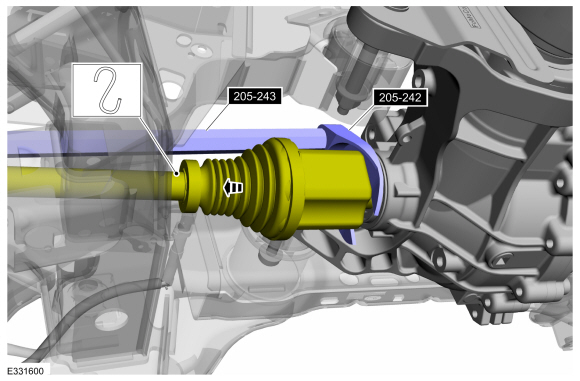
Using the special tools, disconnect the halfshafts from differential and position it aside.
Use Special Service Tool: 205-242 Remover, Fuel Injector. , 205-243 Remover, Halfshaft.
-
Support the halfshaft.
-
Using the special tools, disconnect the halfshafts from differential and position it aside.
 |
-
-
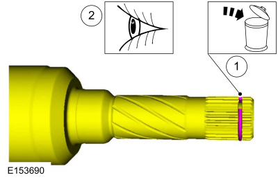
Remove and discard the halfshaft retaining circlip.
-
Inspect the halfshaft end for damage.
-
Remove and discard the halfshaft retaining circlip.
 |
-
Remove the muffler and tail pipe.
Refer to: Muffler and Tailpipe (309-00A Exhaust System - 2.0L EcoBoost (184kW/250PS) – MI4, Removal and Installation).
Refer to: Muffler and Tailpipe (309-00B Exhaust System - 2.7L EcoBoost (238kW/324PS), Removal and Installation).
-
Separate the driveshaft from the drive pinion flange.
-
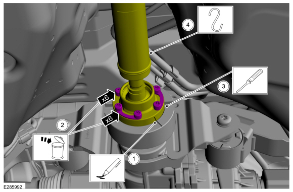
NOTE: Make sure that the component aligns with the installation mark.
Index-mark the driveshaft flange and the RDU companion flange to maintain alignment during installation.
-
Remove and discard the driveshaft to drive pinion companion flange bolts and the retaining straps.
Torque: 26 lb.ft (35 Nm)
-
NOTICE: Do not remove driveshaft from the pinion flange by pulling on the driveshaft tube. Damage to the CV-joint can result.
Using a general equipment, separate the driveshaft from the drive pinion flange.
-
Position and support the driveshaft aside.
-
 |
-
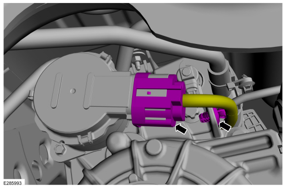
Disconnect the RDU actuator motor electrical connector and detach wiring harness retainer.
 |
-
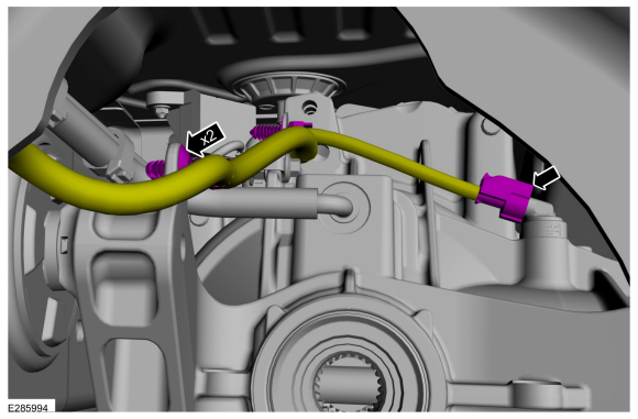
Disconnect the speed sensor electrical connector and detach wiring harness retainers.
 |
-
-
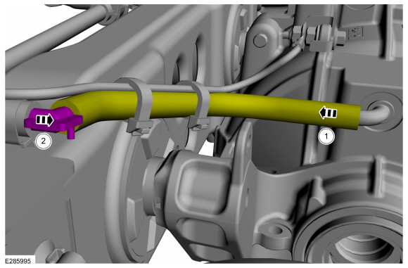
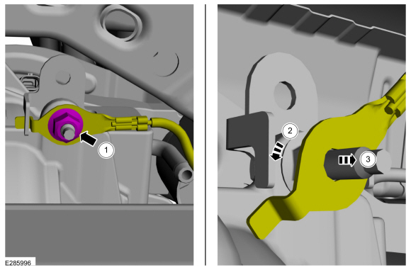
Remove the rear differential vent hose from RDU .
-
Detach the connector and position the vent hose aside.
-
Remove the rear differential vent hose from RDU .
 |
-
NOTE: Re-attach the ground cable after servicing the RDU.
-
Remove the ground cable nut.
Torque: 106 lb.in (12 Nm)
-
Turn the ground cable.
-
Remove the ground cable.
-
Remove the ground cable nut.
 |
-
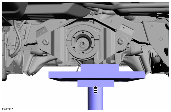
Position a transmission jack and wooden block to secure the RDU .
Use the General Equipment: Transmission Jack
Use the General Equipment: Wooden Block
 |
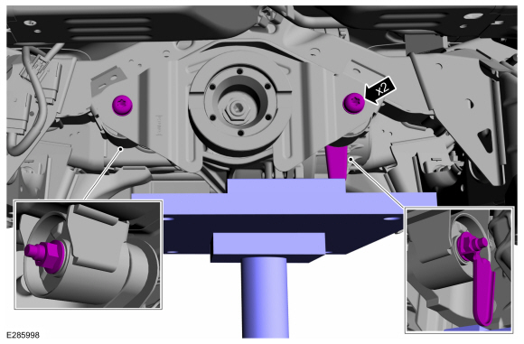
-
Remove the front RDU mounting bolts and nuts.
Use the General Equipment: Transmission Jack
Use the General Equipment: Wooden Block
Torque: 66 lb.ft (90 Nm)
 |
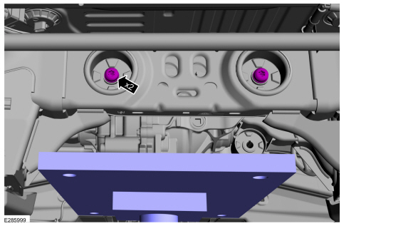
-
Remove the rear RDU mounting bolts.
Torque: 66 lb.ft (90 Nm)
 |
-
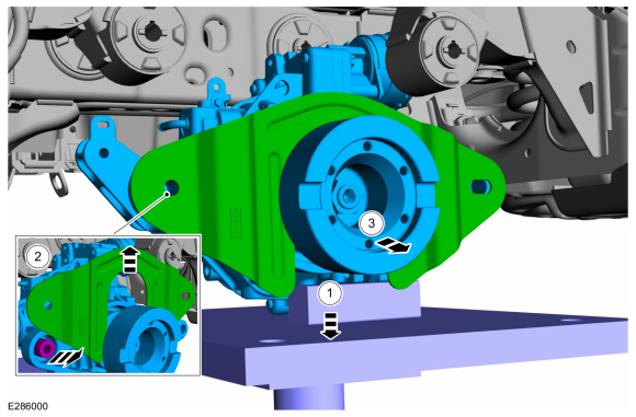
-
Lower the transmission jack.
-
Remove the rear axle arm protection shield and spacer.
-
Remove the rear axle assembly.
-
Lower the transmission jack.
 |
Installation
-
To install, reverse the removal procedure.
-
Check the differential fluid level.
Refer to: Differential Fluid Level Check (205-02 Rear Drive Axle/Differential, General Procedures).
-
NOTICE: If replacing the axle assembly, the AWD control module will need to be reconfigured with the new RDU bar code information. If the new bar code information does not match the existing AWD control module information, driveline damage or driveability concerns can occur.
NOTE: Using the diagnostic scan tool, carry out the rear drive unit calibration routine.
NOTE: The 16/17 -digit alpha numeric bar code is located on the label attached to the RDU . Using the scan tool, configure RDU bar code to AWD module through the OBD port.
 Differential Fluid Level Check. General Procedures
Materials
Name
Specification
Motorcraft® Disconnect Rear Drive Unit FluidXY-75W-QL
-
Check
With the vehicle in NEUTRAL, position it on a hoist...
 Drive Pinion Flange. Removal and Installation
Special Tool(s) /
General Equipment
205-126
(T78P-4851-A)
Holding Fixture, Drive Pinion Flange
205-495Installer, Transmission Output Shaft Flange
Transmission Jack
Flat-Bladed Screwdriver
Two Leg Puller
Wooden Block
Materials
Name
Specification
Motorcraft® Premium Long-Life GreaseXG-1-E1
ESA-M1C75-B
Removal
All vehicles
Rem..
Other information:
Lincoln Nautilus 2018-2026 Service Manual: Controller Area Network (CAN) Module Communications Network - System Operation and Component Description. Description and Operation
System Operation Overview Multiplexing is a method of sending 2 or more signals simultaneously over a single circuit. Multiplexing allows 2 or more electronic modules (nodes) to communicate over a twisted wire pair [data (+) and data (-)] network. The information or messages that can be communicated on these wires consists of commands, status or data. Multiplexing reduces the weight of t..
Lincoln Nautilus 2018-2026 Owners Manual: End User License Agreement
VEHICLE SOFTWARE END USER LICENSE AGREEMENT (EULA) You (“You” or “Your” as applicable) have acquired a vehicle having several devices, including SYNC ® and various control modules, ("DEVICES") that include software licensed or owned by Ford Motor Company and its affiliates ("FORD MOTOR COMPANY"). Those software products of FORD MOTOR COMPANY origin, as well as associated..
Categories
- Manuals Home
- 1st Generation Nautilus Owners Manual
- 1st Generation Nautilus Service Manual
- Engine Oil Capacity and Specification - 2.0L
- Replacing the Rear Wiper Blades
- Opening the Liftgate
- New on site
- Most important about car
Traction Control
How Does Traction Control Work
If your vehicle begins to slide, the system applies the brakes to individual wheels and, when needed, reduces power at the same time. If the wheels spin when accelerating on slippery or loose surfaces, the system reduces power in order to increase traction.
Switching Traction Control On and Off
WARNING: The stability and traction control light illuminates steadily if the system detects a failure. Make sure you did not manually disable the traction control system using the information display controls or the switch. If the stability control and traction control light is still illuminating steadily, have the system serviced by an authorized dealer immediately. Operating your vehicle with the traction co