Lincoln Nautilus: Rear Drive Axle/Differential / Drive Pinion Flange. Removal and Installation
Special Tool(s) / General Equipment
 |
205-126
(T78P-4851-A)
Holding Fixture, Drive Pinion Flange |
 |
205-495 Installer, Transmission Output Shaft Flange |
| Transmission Jack | |
| Flat-Bladed Screwdriver | |
| Two Leg Puller | |
| Wooden Block | |
Materials
| Name | Specification |
|---|---|
| Motorcraft® Premium Long-Life Grease XG-1-E1 |
ESA-M1C75-B |
Removal
All vehicles
-
Remove the muffler and tail pipe.
Refer to: Muffler and Tailpipe (309-00B Exhaust System - 2.7L EcoBoost (238kW/324PS), Removal and Installation).
Refer to: Muffler and Tailpipe (309-00B Exhaust System - 2.7L EcoBoost (238kW/324PS), Removal and Installation).
-
-
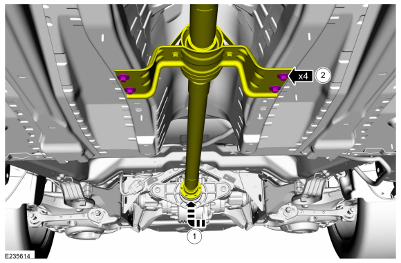
Index mark the driveshaft and the RDU flange for reference during installation.
-
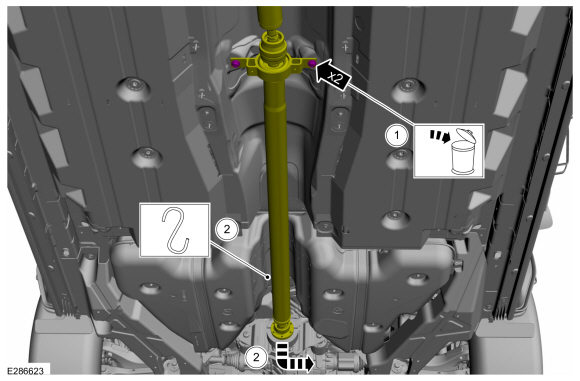
Remove and discard the driveshaft to RDU pinion flange bolts and retaining straps.
-
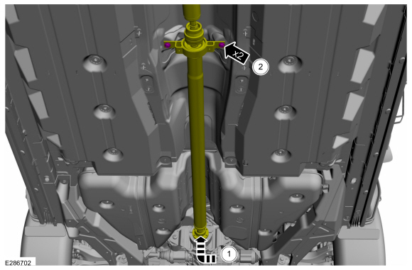
NOTE: Do not remove driveshaft from the pinion flange by pulling on the driveshaft tube. Damage to the CV joint can result.
NOTE: The driveshaft to drive pinion flange is a tight fit and will not come apart until the center bearing is lowered.
Using a general equipment, separate the driveshaft from the drive pinion flange.
Use the General Equipment: Flat-Bladed Screwdriver
-
Index mark the driveshaft and the RDU flange for reference during installation.
 |
2.0L
-
Remove the retainers and the center bearing heat shield.
 |
-
NOTE: Do not allow the driveshaft to hang. Secure the driveshaft so the CV does not over articulate.
Separate the driveshaft from the drive pinion flange.
-
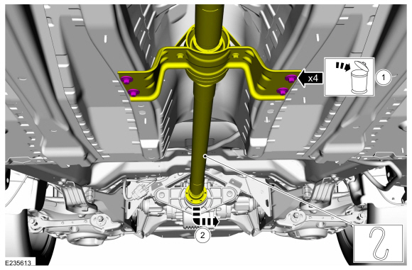
Remove and discard the rear center bearing bolts.
-
Position the rear driveshaft aside.
-
Remove and discard the rear center bearing bolts.
 |
Vehicle equipped with 2.7L EcoBoost Engine
-
NOTE: Do not allow the driveshaft to hang. Secure the driveshaft so the CV does not over articulate.
Separate the driveshaft from the drive pinion flange.
-
Remove and discard the rear center bearing bolts.
-
Position the driveshaft aside.
-
Remove and discard the rear center bearing bolts.
 |
All vehicles
-
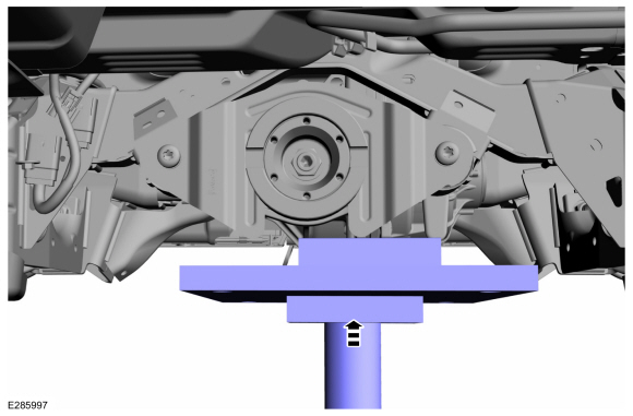
Position a transmission jack and wooden block to secure the RDU .
Use the General Equipment: Transmission Jack
Use the General Equipment: Wooden Block
 |
-
NOTE: Rotational torque of the drive pinion flange must be measured and recorded using a Nm (lb-in) torque wrench for correct pinion bearing preload when reassembled. This will be the torque-to-turn measurement.
Using a dial type torque wrench, measure and record the rotational torque of the drive pinion.
 |
-
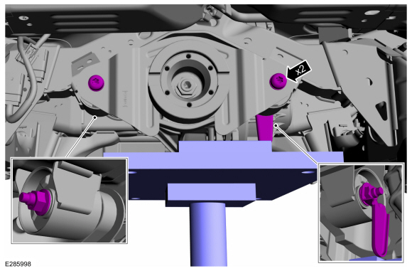
Remove the front RDU mounting bolts and nuts.
 |
-
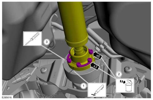
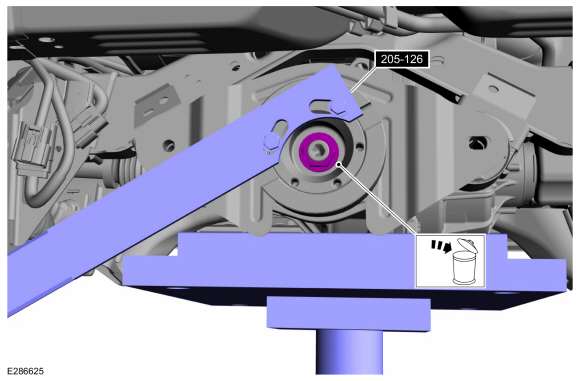
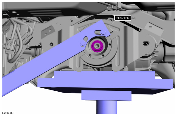
Using the special tool to hold the pinion flange, remove and discard the RDU pinion nut.
Install Special Service Tool: 205-126 (T78P-4851-A) Holding Fixture, Drive Pinion Flange.
 |
-
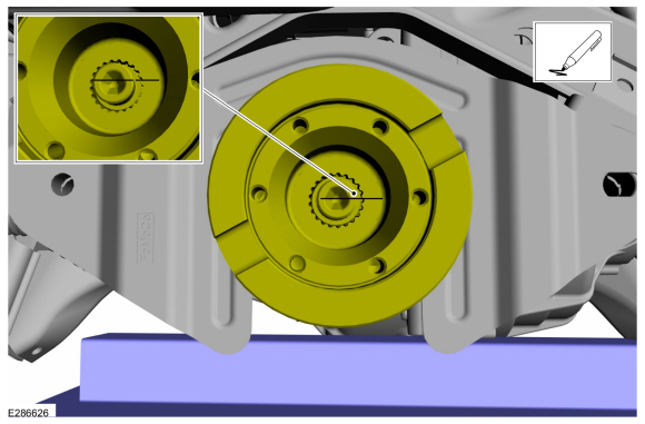
Index-mark the drive pinion flange and the drive pinion stem for reassembly.
 |
-
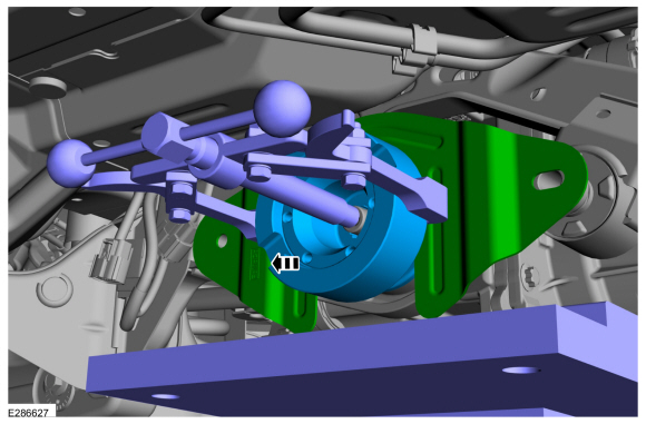
Using a general equipment, remove the drive pinion flange.
Use the General Equipment: Two Leg Puller
 |
Installation
All vehicles
-
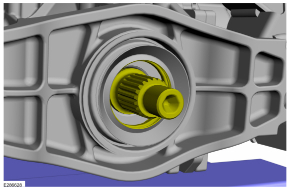
If necessary.
Install a new drive pinion seal.
Refer to: Drive Pinion Seal (205-02 Rear Drive Axle/Differential, Removal and Installation).
-
Lubricate the drive pinion flange mating surfaces with grease.
Material: Motorcraft® Premium Long-Life Grease / XG-1-E1 (ESA-M1C75-B)
 |
-
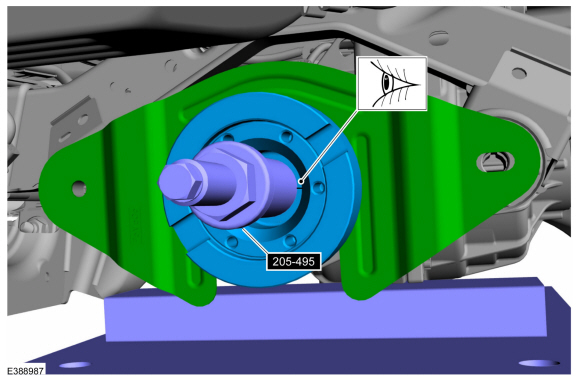
NOTE: Make sure drive pinion flange and drive pinion stem are phased correctly using previously applied mark.
Align the index-mark and using the special tool, install the drive pinion flange.
Use Special Service Tool: 205-495 Installer, Transmission Output Shaft Flange.
 |
-
NOTICE: Under no circumstances is the pinion nut to be backed off to reduce drive pinion bearing preload. If reduced drive pinion bearing preload is required, a new drive pinion collapsible spacer and pinion nut must be installed or damage to the component may occur.
NOTE: Refer to the rotational torque previously recorded with the Nm (lb-in) torque wrench. Tighten the pinion nut in small increments until it is within 0.3 Nm (3 lb-in) of the reference measurement. If 0.3 Nm (3 lb-in) is exceeded, then the collapsible spacer will be damaged and a new rear drive axle will be required.
Using the special tool, install the RDU pinion nut.
Install Special Service Tool: 205-126 (T78P-4851-A) Holding Fixture, Drive Pinion Flange.
 |
-
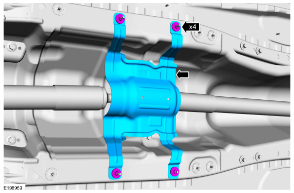
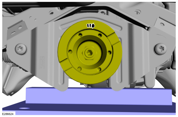
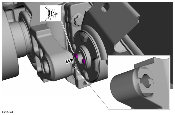
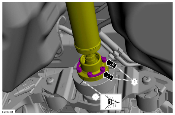
NOTE: Ensure that the subframe bushing anti-rotation tabs are engaged inside the slots on the RDU mounting bracket.
Check the position of the RDU and subframe bushing anti-rotation tabs as shown.
 |
-
Install the front RDU mounting bolts and nuts.
Torque: 76 lb.ft (103 Nm)
|
-
Remove a transmission jack and wooden block from the RDU .
Use the General Equipment: Transmission Jack
Use the General Equipment: Wooden Block
 |
Vehicle equipped with 2.7L EcoBoost Engine
-
Install the driveshaft to the drive pinion flange.
-
NOTE: Align the index-marks when installing the CV flange into the drive pinion flange.
Position the driveshaft CV flange into the drive pinion flange.
-
Install the new rear center bearing bolts.
Torque: 22 lb.ft (30 Nm)
-
 |
2.0L
-
Install the driveshaft to the drive pinion flange.
-
Position the driveshaft CV flange into the drive pinion flange.
-
Install the new rear center bearing bolts.
Torque: 41 lb.ft (55 Nm)
-
Position the driveshaft CV flange into the drive pinion flange.
 |
-
Install the center bearing heat shield and the retainers.
Torque: 106 lb.in (12 Nm)
|
All vehicles
-
-
NOTE: Make sure that the component is installed to the position noted before removal.
Align the index-mark on the driveshaft to the rear axle pinion flange.
-
Install the new driveshaft-to-pinion flange bolts and retaining straps.
Torque: 26 lb.ft (35 Nm)
-
 |
-
Install the muffler and tail pipe.
Refer to: Muffler and Tailpipe (309-00B Exhaust System - 2.7L EcoBoost (238kW/324PS), Removal and Installation).
Refer to: Muffler and Tailpipe (309-00B Exhaust System - 2.7L EcoBoost (238kW/324PS), Removal and Installation).
-
Check the RDU fluid level.
Refer to: Differential Fluid Level Check (205-02 Rear Drive Axle/Differential, General Procedures).
 Axle Assembly. Removal and Installation
Special Tool(s) /
General Equipment
205-242Remover, Fuel InjectorTKIT-1986-LMTKIT-1986-F
205-243Remover, HalfshaftTKIT-1986-LMTKIT-1986-F
Transmission Jack
Wooden Block
Removal
NOTE:
Removal steps in this procedure may contain installation details...
 Drive Pinion Seal. Removal and Installation
Special Tool(s) /
General Equipment
205-208
(T83T-4676-A)
Installer, Drive Pinion Oil SealTKIT-1983-FTKIT-1983-FLMTKIT-1983-FX
Flat Headed Screw Driver
Materials
Name
Specification
Motorcraft® Premium Long-Life GreaseXG-1-E1
ESA-M1C75-B
Removal
Remove the drive pinion flange...
Other information:
Lincoln Nautilus 2018-2026 Service Manual: Rear Exhaust Mounting Bracket. Removal and Installation
Special Tool(s) / General Equipment 8 mm Drill Bit MIG/MAG Welding Equipment Spot Weld Drill Bit Locking Pliers Removal NOTE: LH side shown, RH side similar. NOTE: Factory welds may be substituted with resistance or metal inert gas (MIG) plug welds...
Lincoln Nautilus 2018-2026 Service Manual: Gateway Module A (GWM). Removal and Installation
Removal NOTE: If installing a new module, it is necessary to upload the module configuration information to the scan tool prior to removing the module. This information must be downloaded into the new module after installation. Using a diagnostic scan tool, begin the PMI process for the GWM following the on-screen instructions...
Categories
- Manuals Home
- 1st Generation Nautilus Owners Manual
- 1st Generation Nautilus Service Manual
- Drive Mode Control
- Auto Hold
- USB Ports
- New on site
- Most important about car
Locating the Pre-Collision Assist Sensors

If a message regarding a blocked sensor or camera appears in the information display, something is obstructing the radar signals or camera images. The radar sensor is behind the fascia cover in the center of the lower grille. With a blocked sensor or camera, the system may not function, or performance may reduce. See Pre-Collision Assist – Information Messages.