Lincoln Nautilus: Power Brake Actuation / Brake Booster. Removal and Installation
Removal
NOTICE: Do not spill brake fluid on painted or plastic surfaces or damage to the surface may occur. If brake fluid is spilled onto a painted or plastic surface, immediately wash the surface with water.
NOTE: Removal steps in this procedure may contain installation details.
-
Remove the battery tray.
Refer to: Battery Tray (414-01 Battery, Mounting and Cables, Removal and Installation).
-
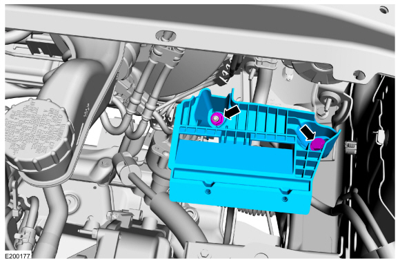
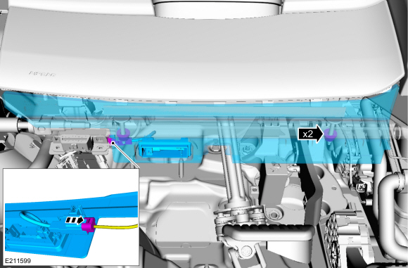
Remove the nut, bolt and the battery tray support bracket.
Torque: 18 lb.ft (24 Nm)
 |
-
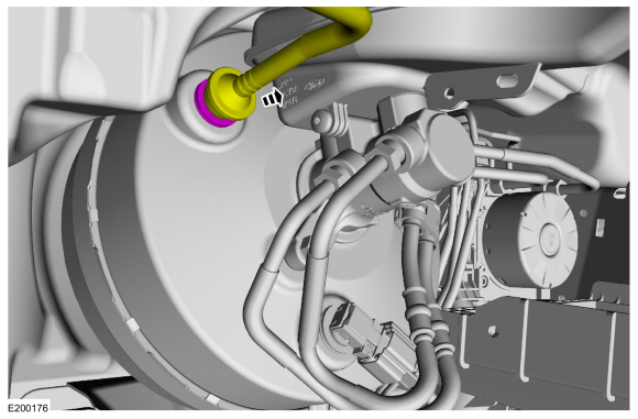
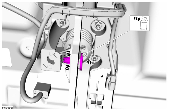
Detach the check valve from the brake booster.
 |
-
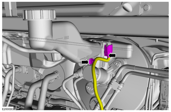
Disconnect the brake fluid level sensor and detach the wiring retainer.
 |
-
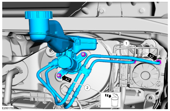
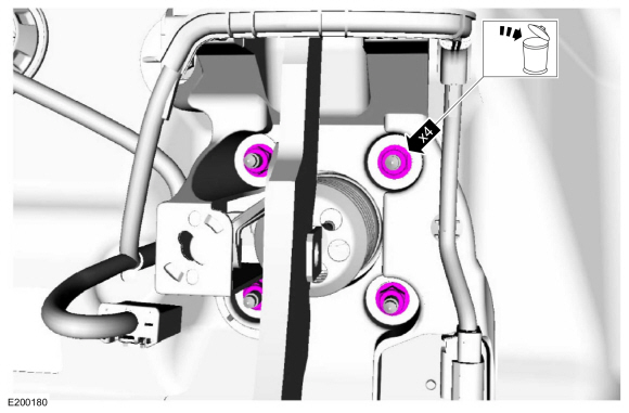
NOTE: Make sure that the master cylinder-to-booster seal is removed with the master cylinder.
Disconnect the brake tube fittings, remove the nuts and remove the brake master cylinder and brake tubes as an assembly. Discard the nuts and O-ring seal.
Torque:
1.: 21 lb.ft (28 Nm)
2.: 18 lb.ft (25 Nm)
 |
-
Remove the nuts, disconnect the electrical connector and remove the LH insulator panel.
 |
-
NOTICE: Do not service the brake pedal or brake booster without first removing the stoplamp switch. This switch must be removed with the brake pedal in the at-rest position. The switch plunger must be compressed for the switch to rotate in the bracket. Attempting to remove the switch when the plunger is extended (during pedal apply) will result in damage to the switch.
Remove the stoplamp switch.
Refer to: Stoplamp Switch (417-01 Exterior Lighting, Removal and Installation).
-
Compress the tabs and remove the clevis pin. Discard the pin.
 |
-
Remove and discard the nuts.
Torque: 17 lb.ft (23 Nm)
 |
-
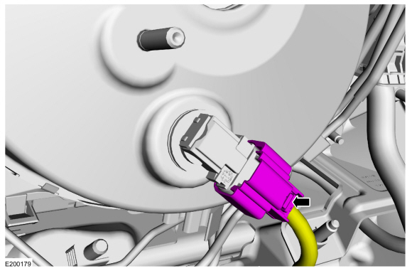
Disconnect the brake booster vacuum sensor electrical connector.
 |
-
Remove the brake booster.
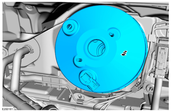 |
Installation
-
NOTICE: Do not press, pull or otherwise move the brake pedal while installing the stoplamp switch. The switch must be installed with the booster push rod attached to the brake pedal and with the brake pedal in the at-rest position. Installing the switch with the brake pedal in any other position will result in incorrect adjustment and may damage the switch.
To install, reverse the removal procedure.
-
Bleed the brake system.
Refer to: Brake System Pressure Bleeding (206-00 Brake System - General Information, General Procedures).

 Brake Vacuum Pump - 2.7L EcoBoost (238kW/324PS). Removal and Installation
Materials
Name
Specification
Motorcraft® High Performance Engine RTV SiliconeTA-357
WSE-M4G323-A6
Motorcraft® Silicone Gasket RemoverZC-30-A, AZC-30-C
-
Motorcraft® Metal Surface Prep WipesZC-31-B
-
Motorcraft® Metal Brake Parts CleanerPM-4-A, PM-4-B, APM-4-C
-
Removal
NOTE:
Removal steps in this procedure may contain inst..
Other information:
Lincoln Nautilus 2018-2026 Service Manual: Parking Brake Switch. Removal and Installation
Removal NOTE: Removal steps in this procedure may contain installation details. Detach the clips and pivot the instrument panel LH lower trim panel downward. Disconnect the EPB switch electrical connector. Remove the 3 screws and the EPB switch. Installation To install, reverse the removal..
Lincoln Nautilus 2018-2026 Service Manual: Alternating Current (AC) Power Outlet Socket. Removal and Installation
Removal WARNING: Disconnect the 12 volt battery before servicing the direct current to alternating current (DC-AC) inverter or alternating current (AC) powerpoint to prevent the risk of high voltage shock. Failure to follow this instruction may result in serious personal injury. Open the floor console stowage bin lid. Remove the floor con..
Categories
- Manuals Home
- 1st Generation Nautilus Owners Manual
- 1st Generation Nautilus Service Manual
- Changing the 12V Battery
- Child Safety Locks
- Replacing the Rear Wiper Blades
- New on site
- Most important about car
Parking Aid Indicators. Parking Aids – Troubleshooting
Parking Aid Indicators
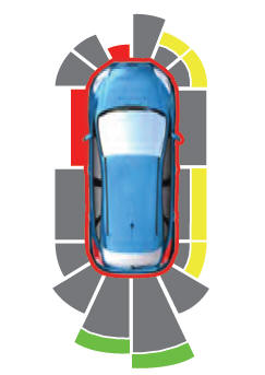
The system provides object distance indication through the information and entertainment display.
As the distance to the object decreases, the indicator waves and the lines move toward the vehicle icon. If there is no object detected, the distance indicator lines are grey.