Lincoln Nautilus: Voltage Converter/Inverter / Direct Current/Direct Current (DC/DC) Converter Control Module - System Operation and Component Description. Description and Operation
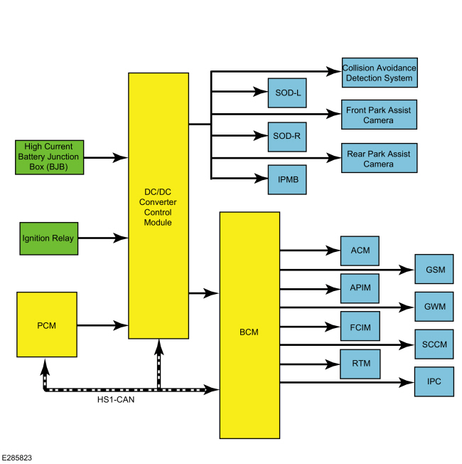
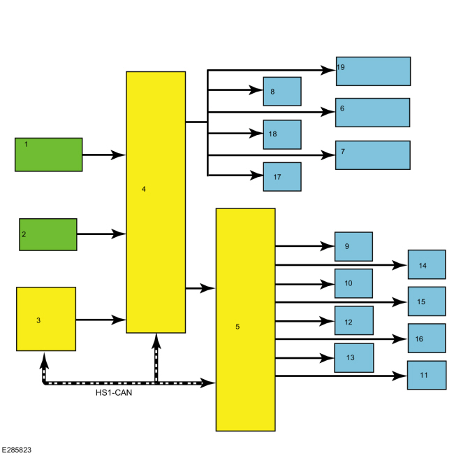
System Diagram
| Item | Description |
|---|---|
| 1 | High Current BJB |
| 2 | Ignition Relay |
| 3 | PCM |
| 4 | DCDC |
| 5 | BCM |
| 6 | Front Park Assist Camera |
| 7 | Rear Park Assist Camera |
| 8 | SODL |
| 9 | ACM |
| 10 | APIM |
| 11 | IPC |
| 12 | FCIM |
| 13 | RTM |
| 14 | GSM |
| 15 | GWM |
| 16 | SCCM |
| 17 | IPMB |
| 18 | SODR |
| 19 | Collision Avoidance Detection System |
System Operation
Network Message Chart
| Broadcast Message | Originating Module | Message Purpose |
| Engine status | PCM | Used to indicate the type of cranking event occurring. If the signal is state 2, Engine Auto Stopped, then the next commanded crank is to be supported. If the signal is state 0, Engine Off, the next crank will be a key crank and the Direct Current/Direct Current (DC/DC) converter control module will not support. |
The Direct Current/Direct Current (DC/DC) converter control module, also known as the Voltage Quality Module (VQM), is responsible for boosting battery voltage to specific components on vehicles equipped with the auto-start-stop system. When the ignition is turned on the Direct Current/Direct Current (DC/DC) converter control module initializes after receiving the Run/Start power feed from the BCM controlled run/start relay.
While in stand-by mode the Direct Current/Direct Current (DC/DC) converter control module performs self-diagnostics and is not producing any boost output voltage. The Direct Current/Direct Current (DC/DC) converter control module is simply passing battery voltage straight through to downstream loads when it is in stand-by mode.
The Direct Current/Direct Current (DC/DC) converter control module continuously communicates it's status to the PCM via HS-CAN1 . If the Direct Current/Direct Current (DC/DC) converter control module is overloaded, overheated, or other faults are present the PCM disables the auto-start-stop system. If a fault is detected, the PCM may restart the engine if an auto-start-stop event is already in progress. During an auto-start-stop event the engine shuts down automatically after vehicle speed is zero. As the engine begins shutting down, there is an initial battery voltage drop due to the engine shutting off and the alternator no longer providing output current.
Once the engine is no longer spinning, the electrical system is fully supported by the vehicle battery. The electrical load present in the engine off phase of the auto-start-stop event causes a gradual decline in battery voltage. This gradual decline of battery voltage is the second voltage transition. The third voltage transition occurs during the engine restart. The system voltage drops, followed by the system voltage increasing to the regulation voltage point determined by the alternator output.
Prior to the engine restart, the PCM sends a low-side drive command to the low voltage Direct Current/Direct Current (DC/DC) converter. The low voltage Direct Current/Direct Current (DC/DC) converter is switched into Boost mode to stabilize/boost its output until the engine has started and system voltage regulation is established by the alternator. The converter provides the stabilized or boost output voltage until one of the following occurs:
- Boost time exceeds 5 seconds
- System input voltage exceeds targeted output
The Direct Current/Direct Current (DC/DC) converter control module has full bypass or stand-by mode functionality within an input of 6V-16V. The Direct Current/Direct Current (DC/DC) converter control module must be able to provide the boosted voltage with a minimum 6V power net input voltage. If the supply voltage goes outside the voltage range, the Direct Current/Direct Current (DC/DC) converter control module recovers without user intervention when the supply voltage returns to the normal operating range. The Direct Current/Direct Current (DC/DC) converter control module determines the stabilized output voltage to be targeted by continuously measuring the Direct Current/Direct Current (DC/DC) converter control module input voltage. Prior to the restart event, the Direct Current/Direct Current (DC/DC) converter control module receives the RE-CRANK signal and sets the boosted output voltage target to be equivalent to the measured input voltage. This makes sure the output voltage to the supported loads does not change.
Malfunction of the system does not lead to non-function of other vehicle systems. The system enters bypass mode if:
- a thermal overload condition exists.
- there is a Direct Current/Direct Current (DC/DC) converter control module failure.
- the output voltage is more than 1V below input voltage and voltage boost is not available.
The Direct Current/Direct Current (DC/DC) converter control module self-protects against overheating and self-recovers without user interaction after an overheating event and is internally protected from short-circuits.
Component Description
The Direct Current/Direct Current (DC/DC) converter control module is connected in series between the high current fuse box and a select number of non-safety electrical loads. The majority of the loads are fused through the BCM and remaining loads are not fused and are switched on by a smart transistor located internal to the Direct Current/Direct Current (DC/DC) converter control module. The smart transistor acts as a fuse and shuts off power in the event of a short to ground. The Direct Current/Direct Current (DC/DC) converter control module has a dedicated body ground and incorporates a hardwired signal circuit from the PCM which notifies the Direct Current/Direct Current (DC/DC) converter control module prior to the engine cranking during an auto-start event.
 Direct Current/Direct Current (DC/DC) Converter Control Module - Overview. Description and Operation
OVERVIEW
The
Low voltage Direct Current/Direct Current (DC/DC) converter, also known
as the Voltage Quality Module (VQM), is on vehicles equipped with the
auto-start-stop system...
 Direct Current/Alternating Current (DC/AC) Inverter. Diagnosis and Testing
Inspection and Verification
Before
diagnosing or repairing the Direct Current/Alternating Current (DC/AC)
Inverter system refer to the Owner's Literature and
REFER to: Direct Current/Alternating Current (DC/AC) Inverter -
System Operation and Component Description (414-05 Voltage
Converter/Inverter, Description and Operation)...
Other information:
Lincoln Nautilus 2018-2026 Service Manual: Front Brake Flexible Hose. Removal and Installation
Removal NOTICE: If the fluid is spilled on the paintwork, the affected area must be immediately washed down with cold water. NOTE: Removal steps in this procedure may contain installation details. NOTICE: Make sure that all openings are sealed...
Lincoln Nautilus 2018-2026 Owners Manual: Using MyKey With Remote Start Systems. MyKey – Troubleshooting
Using MyKey With Remote Start Systems MyKey is not compatible with non Lincoln-approved, aftermarket remote start systems. If you choose to install a remote start system, see an authorized dealer for a Lincoln-approved remote start system. MyKey – Troubleshooting ..
Categories
- Manuals Home
- 1st Generation Nautilus Owners Manual
- 1st Generation Nautilus Service Manual
- Normal Scheduled Maintenance
- Engine Oil Capacity and Specification - 2.0L
- Opening and Closing the Hood
- New on site
- Most important about car
Opening and Closing the Hood
Opening the Hood