Lincoln Nautilus: Ethernet Module Communications Network / Ethernet Module Communications Network - System Operation and Component Description. Description and Operation
System Operation
Overview
The Ethernet communication network is a high speed communication network providing high bandwidth data transfer and improved data security to support module updates over the air, driver assistance systems, multi media systems and improved connectivity. The Ethernet communication network connects the TCU and the GWM and other connected modules such as the APIM and IPC dependent on the vehicle configuration.
The network is primarily utilized for the update over the air feature to quickly and securely transfer data from the connected external source (data cloud) through the TCU to the GWM where it is distributed to the receiving module on the vehicle.
System Diagram
NOTE: The system diagrams include all component options. Some components may not be equipped on the vehicle.
*.sttxt { visibility: hidden; } *.stcallout { visibility: visible; } E348856 1 DLC 2 Gateway Module 3 Primary Cellular Antenna 4 APIM 5 TCU 6 Cloud-based Connectivity| Item | Description |
|---|---|
| 1 | DLC |
| 2 | GWM |
| 3 | Primary Cellular Antenna |
| 4 | APIM |
| 5 | TCU |
| 6 | Cloud-based Connectivity |
System Operation
The Ethernet communication network is a high speed communication network providing a data transfer speeds of 100Mbps to 1Gbps, to support the on vehicle applications that require high data transfer rates such as over the air updates, driver assistance systems (Video data, radar data, ultrasonic data), multi media systems and connectivity to external devices. The GWM is the primary module within the Ethernet communication network and manages the distribution of data to the other connected modules on the network. Data from external sources (cloud based data) is received by the TCU and transferred over the Ethernet communication network to the GWM where it is distributed to the other modules connected to the Ethernet communication network and the vehicle communication networks. The modules connected to the Ethernet communication network are dependant on the vehicle configuration.
Component Description
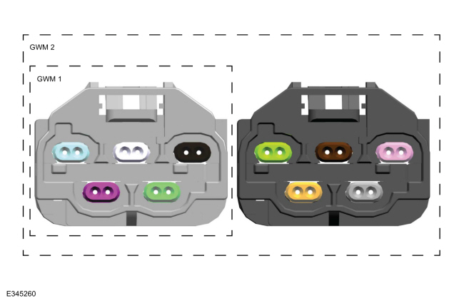
Ethernet Network Gateway Module Connector
The Ethernet network connects to the GWM through master connectors. The first generation of the enhanced central gateway module GWM has one Ethernet master connector. The second generation is equipped with two. Each master connector is capable of housing 5 Ethernet cable connections. The number of Ethernet network connections on each vehicle is determined by the individual vehicle requirements, not all of the available Ethernet connections will be used. Refer to the system diagram above for details of the Ethernet communication network connections on this vehicle.
Each individual Ethernet cable connects into one of the master connectors, their location within the master connectors is determined by the vehicle program and may not be the same for all vehicle lines. Each individual Ethernet cable has a color coded connector end and each color is aligned to a specific module across all vehicle lines.
The Ethernet cable connector end color assignment is as follows:
- Jet Black dedicated for the IPMA - ADAS module
- Pure White dedicated for the HUD module
- Light Blue dedicated for the TCU
- Claret Violet dedicated for the APIM
- May Green dedicated for the IPC
- Nut Brown dedicated for the Diagnostic
- Platinum Grey dedicated for the DSRC (Dedicated Short Range Communications) module
- Light Pink dedicated for the PCM
- Pastel Orange dedicated for the TCU 2
- Pastel Green dedicated for theBCM

| Item | Description |
|---|---|
| 1 | Enhanced central gateway module GWM 1 |
| 2 | Enhanced central gateway module GWM 2 |
NOTE: The Number of Ethernet master connectors and Ethernet communication circuit connections depicted in the graphic above are for description of capability only and may not represent what the vehicle is equipped with.
Gateway Module
The GWM receives data from the Ethernet network and distributes the data to the receiving modules across all of the vehicle networks.
Ethernet Cable
The Ethernet communication network cables are twisted unshielded jacketed cables connected to form a point to point network.

 Ethernet Module Communications Network. Diagnosis and Testing
Diagnostic Trouble Code (DTC) Chart
Diagnostics in this manual assume a certain skill level and knowledge of Ford-specific diagnostic practices. REFER to: Diagnostic Methods (100-00 General Information, Description and Operation)...
Other information:
Lincoln Nautilus 2018-2026 Service Manual: Passenger Airbag Deactivation (PAD) Indicator. Removal and Installation
Special Tool(s) / General Equipment Interior Trim Remover Removal NOTE: Interior rear view mirror removed for clarity. Remove the IPMA cover. Release the IPMA cover clips. Use the General Equipment: Interior Trim Remover Disconnect the PAD indicator electrical connector...
Lincoln Nautilus 2018-2026 Service Manual: Evaporator Temperature Sensor. Removal and Installation
Removal NOTE: The evaporator temperature sensor is available only as part of the climate control housing. Remove the climate control housing. Refer to: Climate Control Housing (412-00) . Installation Transfer the components from the old housing to the new housing as needed...
Categories
- Manuals Home
- 1st Generation Nautilus Owners Manual
- 1st Generation Nautilus Service Manual
- Auto-Start-Stop
- Opening the Liftgate
- USB Ports
- New on site
- Most important about car
Programming the Garage Door Opener to Your Garage Door Opener Motor