Lincoln Nautilus: Ethernet Module Communications Network / Ethernet Module Communications Network. Diagnosis and Testing
Diagnostic Trouble Code (DTC) Chart
Diagnostics in this manual assume a certain skill level and knowledge of Ford-specific diagnostic practices.
REFER to: Diagnostic Methods (100-00 General Information, Description and Operation).
| Module | DTC | Description | Action |
|---|---|---|---|
| APIM | U2400:81 | Ethernet Failure With Gateway Module A (GWM): Invalid Serial Data Received | GO to Pinpoint Test A |
| APIM | U2400:92 | Ethernet Failure With Gateway Module A (GWM): Performance Or Incorrect Operation | GO to Pinpoint Test A |
| GWM | U2401:00 | Ethernet Failure With Accessory Protocol Interface Module (APIM): No Sub Type Information | GO to Pinpoint Test B |
| GWM | U2401:81 | Ethernet Failure With Accessory Protocol Interface Module (APIM): Invalid Serial Data Received | GO to Pinpoint Test A |
| GWM | U2401:92 | Ethernet Failure With Accessory Protocol Interface Module (APIM): Performance Or Incorrect Operation | GO to Pinpoint Test A |
| GWM | U2402:00 | Ethernet Failure With Telematic Control Unit Module (TCU): No Sub Type Information | GO to Pinpoint Test B |
| GWM | U2402:81 | Ethernet Failure With Telematic Control Unit Module (TCU): Invalid Serial Data Received | GO to Pinpoint Test A |
| GWM | U2402:92 | Ethernet Failure With Telematic Control Unit Module (TCU): Performance Or Incorrect Operation | GO to Pinpoint Test A |
Pinpoint Tests
|
Refer to Wiring Diagrams Cell 14 for schematic and connector information. Normal Operation and Fault Conditions Ethernet Cable Testing At Cable End 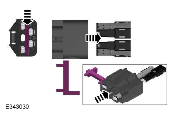
To test the Ethernet cable in question at the GWM , the cable must be removed from the GWM master connector to gain access to the connector pins where probing can take place (refer to the illustration above). The Ethernet cable connector end identification
color can be used to identify the module the Ethernet cable is connected
to. Refer to the chart in the Description and Operation section for the
color assignment. REFER to: Ethernet Module Communications Network -
System Operation and Component Description (418-00B Ethernet Module
Communications Network, Description and Operation). 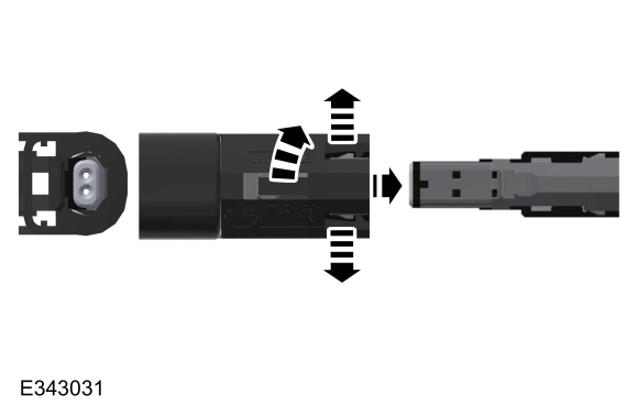
To test the Ethernet cable in question at the all other applicable modules, the cable must be removed from the connector housing to gain access to the connector pins where probing can take place. (refer to the illustration above) Ethernet Cable Testing At Cable In-line Connection 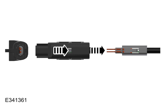
.jpg)
To test the Ethernet cable in question at the in-line connection, the cable must be removed from the connector housing to gain access to the connector pins where probing can take place (refer to the illustration above).
REFER to: Ethernet Module Communications Network - System Operation and
Component Description (418-00B Ethernet Module Communications Network,
Description and Operation). DTC Fault Trigger Conditions
Possible Sources
|
|||||||||||||||||||||
| A1 CHECK THE NETWORK COMMUNICATION | |||||||||||||||||||||
Does the module in question, APIM , TCU pass the network test?
|
|||||||||||||||||||||
| A2 CHECK FOR DIAGNOSTIC TROUBLE CODES (DTCS) | |||||||||||||||||||||
Are any non-Ethernet related Diagnostic Trouble Codes (DTCs) present?
|
|||||||||||||||||||||
| A3 CHECK THE ETHERNET CIRCUIT FOR A SHORT TO GROUND | |||||||||||||||||||||
Are the resistances greater than 10,000 ohms?
|
|||||||||||||||||||||
| A4 CHECK THE ETHERNET CIRCUIT FOR A SHORT TOGETHER | |||||||||||||||||||||
Is the resistance greater than 10,000 ohms?
|
|||||||||||||||||||||
| A5 CHECK THE ETHERNET CIRCUIT FOR A SHORT TO POWER | |||||||||||||||||||||
Is any voltage present?
|
|||||||||||||||||||||
| A6 CHECK THE ETHERNET CIRCUIT FOR AN OPEN | |||||||||||||||||||||
Are the resistances less than 3 ohms?
|
|||||||||||||||||||||
| A7 RECHECK FOR DIAGNOSTIC TROUBLE CODES (DTCS) | |||||||||||||||||||||
Is the DTC still present?
|
|||||||||||||||||||||
| A8 CHECK FOR CORRECT APIM (SYNC MODULE) OPERATION | |||||||||||||||||||||
Is the concern still present?
|
|||||||||||||||||||||
| A9 CHECK FOR CORRECT TCU (TELEMATIC CONTROL UNIT MODULE) OPERATION | |||||||||||||||||||||
Is the concern still present?
|
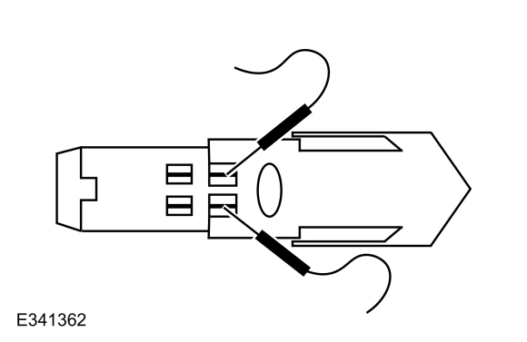
.jpg) Ethernet cable , pin 1
Ethernet cable , pin 1
.jpg)
.jpg)
|
Refer to Wiring Diagrams Cell 14 for schematic and connector information. Normal Operation and Fault Conditions Ethernet Cable Testing At Cable End
To test the Ethernet cable in question at the GWM , the cable must be removed from the GWM master connector to gain access to the connector pins where probing can take place (refer to the illustration above). The Ethernet cable connector end identification
color can be used to identify the module the Ethernet cable is connected
to. Refer to the chart in the Description and Operation section for the
color assignment. REFER to: Ethernet Module Communications Network -
System Operation and Component Description (418-00B Ethernet Module
Communications Network, Description and Operation).
To test the Ethernet cable in question at the all other applicable modules, the cable must be removed from the connector housing to gain access to the connector pins where probing can take place. (refer to the illustrations above) Ethernet Cable Testing At Cable In-line Connection
To test the Ethernet cable in question at the in-line connection, the cable must be removed from the connector housing to gain access to the connector pins where probing can take place (refer to the illustrations above).
REFER to: Ethernet Module Communications Network - System Operation and
Component Description (418-00B Ethernet Module Communications Network,
Description and Operation). DTC Fault Trigger Conditions
Possible Sources
|
|||||||||||||
| B1 CHECK THE NETWORK COMMUNICATION | |||||||||||||
Does the module in question (APIM , TCU ) pass the network test?
|
|||||||||||||
| B2 CHECK FOR DIAGNOSTIC TROUBLE CODES (DTCS) | |||||||||||||
Are any Diagnostic Trouble Codes (DTCs) present?
|
|||||||||||||
| B3 RESET THE MODULE IN QUESTION (APIM, TCU) | |||||||||||||
Does the authorization state PID still indicate Unprovisioned?
|
|||||||||||||
| B4 RECHECK FOR DIAGNOSTIC TROUBLE CODES (DTCS) | |||||||||||||
Is DTC U2401:00 or U2402:00 still present?
|
|||||||||||||
| B5 CHECK THE ETHERNET CIRCUIT FOR AN OPEN | |||||||||||||
Are the resistances less than 3 ohms?
|
|||||||||||||
| B6 CHECK THE ETHERNET CIRCUIT FOR A SHORT TO GROUND | |||||||||||||
Are the resistances greater than 10,000 ohms?
|
|||||||||||||
| B7 CHECK THE ETHERNET CIRCUIT FOR A SHORT TOGETHER | |||||||||||||
Is the resistance greater than 10,000 ohms?
|
|||||||||||||
| B8 CHECK THE ETHERNET CIRCUIT FOR A SHORT TO POWER | |||||||||||||
Is any voltage present?
|
|||||||||||||
| B9 CHECK FOR CORRECT APIM (SYNC MODULE) OPERATION | |||||||||||||
Is the concern still present?
|
|||||||||||||
| B10 CHECK FOR CORRECT TCU (TELEMATIC CONTROL UNIT MODULE) OPERATION | |||||||||||||
Is the concern still present?
|
 Ethernet Module Communications Network - System Operation and Component Description. Description and Operation
System Operation
Overview
The
Ethernet communication network is a high speed communication network
providing high bandwidth data transfer and improved data security to
support module updates over the air, driver assistance systems, multi
media systems and improved connectivity...

Other information:
Lincoln Nautilus 2018-2026 Service Manual: Noise, Vibration and Harshness (NVH). Description and Operation
Acceptable Noise, Vibration and Harshness (NVH) Noise is any undesirable sound, usually unpleasant in nature. Vibration is any motion, shaking or trembling, that can be felt or seen when an object moves back and forth or up and down. Harshness is a ride quality issue where the vehicle's response to the road transmits sharply to the customer. Harshness normally describes a firmer than usua..
Lincoln Nautilus 2018-2026 Service Manual: Rear Seats. Diagnosis and Testing
Symptom Chart(s) Symptom Chart: Rear Seats Diagnostics in this manual assume a certain skill level and knowledge of Ford-specific diagnostic practices. REFER to: Diagnostic Methods (100-00 General Information, Description and Operation). Symptom Chart Condition Possible Sources Actions Both heated rear seats are inoperative ..
Categories
- Manuals Home
- 1st Generation Nautilus Owners Manual
- 1st Generation Nautilus Service Manual
- Massage Seats
- Engine Oil Capacity and Specification - 2.0L
- Child Safety Locks
- New on site
- Most important about car
Parking Aid Indicators. Parking Aids – Troubleshooting
Parking Aid Indicators
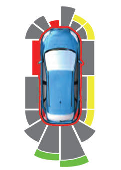
The system provides object distance indication through the information and entertainment display.
As the distance to the object decreases, the indicator waves and the lines move toward the vehicle icon. If there is no object detected, the distance indicator lines are grey.