Lincoln Nautilus: Front End Sheet Metal Repairs / Cowl Panel. Removal and Installation
Special Tool(s) / General Equipment
| Resistance Spotwelding Equipment | |
| 8 mm Drill Bit | |
| MIG/MAG Welding Equipment | |
| Spot Weld Drill Bit | |
| Locking Pliers |
Materials
| Name | Specification |
|---|---|
| Seam Sealer TA-2-B, 3M™ 08308, LORD Fusor® 803DTM |
- |
Removal
NOTE: Factory welds may be substituted with resistance or metal inert gas (MIG) plug welds. Resistance welds may not be placed directly over original location. They must be placed adjacent to original location and match factory welds in quantity. Metal inert gas (MIG) plug welds must equal factory welds in both location and quantity.
NOTE: Adequately protect all adjacent areas against cutting, grinding and welding procedures.
-
Depower the SRS .
Refer to: Supplemental Restraint System (SRS) Depowering (501-20B Supplemental Restraint System, General Procedures).
-
If Required:
Dimensionally restore the vehicle to pre-damage condition.
Refer to: Body and Frame (501-26 Body Repairs - Vehicle Specific Information and Tolerance Checks, Description and Operation).
-
Remove the following items:
-
Remove the hood.
Refer to: Hood (501-02 Front End Body Panels, Removal and Installation).
-
Remove the cowl panel grille.
Refer to: Cowl Panel Grille (501-02 Front End Body Panels, Removal and Installation).
-
Remove the windshield wiper motor and associated linkage.
Refer to: Windshield Wiper Motor (501-16 Wipers and Washers, Removal and Installation).
Refer to: Wiper Linkage Assembly (501-16 Wipers and Washers, Removal and Installation).
-
Remove the instrument panel and console.
Refer to: Floor Console (501-12 Instrument Panel and Console, Removal and Installation).
Refer to: Instrument Panel (501-12 Instrument Panel and Console, Removal and Installation).
-
Remove the windshield glass.
Refer to: Fixed Glass (501-11 Glass, Frames and Mechanisms, General Procedures).
-
Remove the hood.
-
Position electrical modules and wiring harnesses away from the working area.
-
Remove the welds.
Use the General Equipment: Spot Weld Drill Bit
 |
-
Remove the welds.
Use the General Equipment: Spot Weld Drill Bit
.jpg) |
-
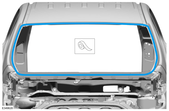
NOTE: Pay particular attention to the location of adhesives or sealers to aid in installation.
Remove the welds and the cowl panel.
Use the General Equipment: Spot Weld Drill Bit
.jpg) |
Installation
NOTE: Factory welds may be substituted with resistance or metal inert gas (MIG) plug welds. Resistance welds may not be placed directly over original location. They must be placed adjacent to original location and match factory welds in quantity. Metal inert gas (MIG) plug welds must equal factory welds in both location and quantity.
NOTE: Adequately protect all adjacent areas against cutting, grinding and welding procedures.
-
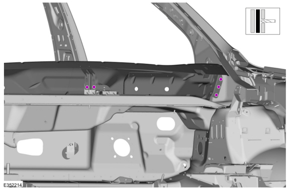
Drill plug weld holes.
Use the General Equipment: 8 mm Drill Bit
.jpg) |
-
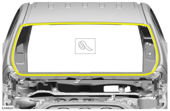
Install, properly position, clamp and weld the replacement cowl panel.
Use the General Equipment: Locking Pliers
Use the General Equipment: Resistance Spotwelding Equipment
Use the General Equipment: MIG/MAG Welding Equipment
.jpg) |
-
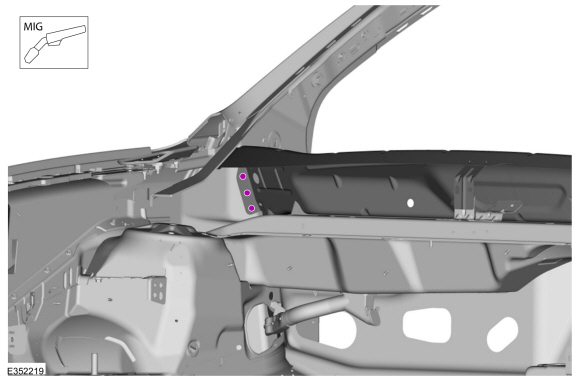
Install the welds.
Use the General Equipment: MIG/MAG Welding Equipment
 |
-
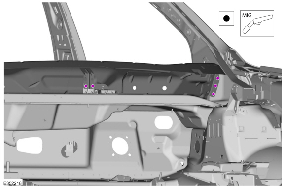
Install the welds.
Use the General Equipment: Resistance Spotwelding Equipment
Use the General Equipment: MIG/MAG Welding Equipment
 |
-
Dress all welds as required using typical metal finishing techniques and materials.
-
Seam Sealing:
All seams must be sealed to production level.
Material: Seam Sealer / TA-2-B, 3M™ 08308, LORD Fusor® 803DTM
.jpg) |
-
Sand to remove old adhesive, paint, e-coat and clean.
.jpg) |
-
Apply a Ford approved epoxy-based primer and allow to dry.
.jpg) |
-
Mask the windshield channel.
 |
-
Refinish the entire repair using a Ford approved paint system.
-
Remove the masking material from the windshield channel.
 |
-
VIN Plate:
Install a new VIN plate.
Refer to: Identification Codes (100-01 Identification Codes, Description and Operation).
-
Install the windshield glass.
Refer to: Fixed Glass (501-11 Glass, Frames and Mechanisms, General Procedures).
-
Restore corrosion protection.
Refer to: Corrosion Prevention (501-25 Body Repairs - General Information, General Procedures).
-
Reposition the wiring harnesses and electrical modules in original location.
-
Remove the following items:
-
Install the instrument panel and console.
Refer to: Instrument Panel (501-12 Instrument Panel and Console, Removal and Installation).
Refer to: Floor Console (501-12 Instrument Panel and Console, Removal and Installation).
-
Install the windshield wiper components.
Refer to: Windshield Wiper Motor (501-16 Wipers and Washers, Removal and Installation).
Refer to: Wiper Linkage Assembly (501-16 Wipers and Washers, Removal and Installation).
-
Install the cowl panel grille.
Refer to: Cowl Panel Grille (501-02 Front End Body Panels, Removal and Installation).
-
Install the hood and align the hood.
Refer to: Hood (501-02 Front End Body Panels, Removal and Installation).
-
Install the instrument panel and console.
-
Repower the SRS .
Refer to: Supplemental Restraint System (SRS) Repowering (501-20B Supplemental Restraint System, General Procedures).

 Dash Panel. Removal and Installation
Special Tool(s) /
General Equipment
Scraper for Straight Edges
Hot Air Gun
8 mm Drill Bit
MIG/MAG Welding Equipment
Spot Weld Drill Bit
Locking Pliers
Materials
Name
Specification
Seam SealerTA-2-B, 3M™ 08308, LORD Fusor® 803DTM
-
Removal
NOTE:
Roof removed for clarity...
Other information:
Lincoln Nautilus 2018-2026 Owners Manual: Automatic Transmission
Automatic Transmission Precautions WARNING: Always fully apply the parking brake and make sure you shift into park (P). Failure to follow this instruction could result in personal injury or death. WARNING: Do not apply the brake pedal and accelerator pedal simultaneously...
Lincoln Nautilus 2018-2026 Owners Manual: Instrument Cluster Indicators
Indicators notify you of various features that are active on your vehicle. Adaptive Cruise Control Adaptive Steering Airbag Auto Hold Automatic High Beam Auto Start-Stop Blind Spot Information System Cruise Control (If Equipped) Front Fog Lamp Headlamp High Beam Hill Start Assist Parking Lamps Stability and Traction Control Turn Signal..
Categories
- Manuals Home
- 1st Generation Nautilus Owners Manual
- 1st Generation Nautilus Service Manual
- Auto-Start-Stop
- Engine Oil Capacity and Specification - 2.0L
- Massage Seats
- New on site
- Most important about car
Opening and Closing the Hood
Opening the Hood