Lincoln Nautilus: Seatbelt Systems / Front Seatbelt Retractor and Pretensioner. Removal and Installation
Removal
NOTE: Removal steps in this procedure may contain installation details.
NOTE: RH shown, LH similar.
-
Depower the SRS .
Refer to: Supplemental Restraint System (SRS) Depowering (501-20 Supplemental Restraint System) .
-
Remove the B-pillar trim panel.
Refer to: B-Pillar Trim Panel (501-05 Interior Trim and Ornamentation, Removal and Installation).
-
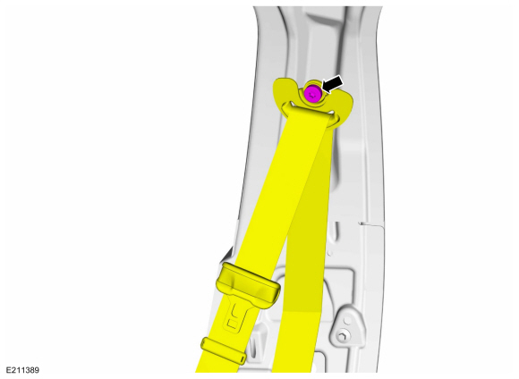
Remove the seatbelt guide bolt.
Torque: 48 lb.in (5.4 Nm)
.jpg) |
-
Remove the D-ring bolt and position the seatbelt aside.
Torque: 30 lb.ft (40 Nm)
 |
-
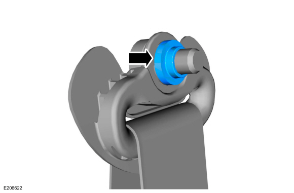
NOTE: This step is only necessary when installing a new component.
NOTE: The spacer is part of the seatbelt shoulder height adjuster and must be reused when a new component is installed.
Remove the spacer from the D-ring bolt.
 |
-
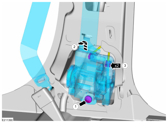
Remove the seatbelt retractor and pretensioner.
-
Remove the bolt.
Torque: 30 lb.ft (40 Nm)
-
Push the seatbelt retractor up and out.
-
Disconnect the electrical connector(s).
-
Remove the bolt.
 |
Installation
NOTE: During installation, make sure the seatbelt webbing is not twisted and the seatbelts and buckles are accessible to the occupants.
-
To install, reverse the removal procedure.
-
Repower the SRS .
Refer to: Supplemental Restraint System (SRS) Repowering (501-20 Supplemental Restraint System) .
-
Check the seatbelt system for correct operation.
Refer to: Seatbelt Systems (501-20 Seatbelt Systems) .
 Front Seatbelt Buckle. Removal and Installation
Removal
NOTE:
Removal steps in this procedure may contain installation details.
NOTE:
Driver seat shown, passenger seat similar.
Remove the front seat...
 Rear Center Seatbelt Buckle. Removal and Installation
Removal
NOTE:
Removal steps in this procedure may contain installation details.
Remove the rear seat cushion.
Refer to: Rear Seat Cushion (501-10B Rear Seats, Removal and Installation)...
Other information:
Lincoln Nautilus 2018-2026 Service Manual: Auxiliary Power Point. Removal and Installation
Special Tool(s) / General Equipment 501-194Remover, Power PointTKIT-2014D-ROW2TKIT-2014D-FL_ROW Removal Open the power point cover. Position the power point extractor so that it engages in the adjacent slots in the power point socket...
Lincoln Nautilus 2018-2026 Service Manual: Front Side Member Section. Removal and Installation
Special Tool(s) / General Equipment Resistance Spotwelding Equipment Spherical Cutter Air Body Saw 8 mm Drill Bit MIG/MAG Welding Equipment Spot Weld Drill Bit Locking Pliers Materials Name Specification Seam SealerTA-2-B, 3M™ 08308, LORD Fusor® 803DTM - Removal NOTE: This procedure is intended for sectioning a small portion of t..
Categories
- Manuals Home
- 1st Generation Nautilus Owners Manual
- 1st Generation Nautilus Service Manual
- Opening the Liftgate
- Engine Oil Capacity and Specification - 2.0L
- Drive Mode Control
- New on site
- Most important about car
Locating the Pre-Collision Assist Sensors

If a message regarding a blocked sensor or camera appears in the information display, something is obstructing the radar signals or camera images. The radar sensor is behind the fascia cover in the center of the lower grille. With a blocked sensor or camera, the system may not function, or performance may reduce. See Pre-Collision Assist – Information Messages.