Lincoln Nautilus: Engine System - General Information / Valve Train Analysis - Gasoline. General Procedures
Lincoln Nautilus 2018-2026 Service Manual / Powertrain / Engine / Engine System - General Information / Valve Train Analysis - Gasoline. General Procedures
Valve Train Analysis - Engine Off, Valve Cover Removed
NOTE: The following component inspections are used to diagnose valve train concerns.
-
Check for damaged or severely worn parts and correct assembly.
Valve Train Analysis - Camshaft Lobe Lift
-
Remove the spark plugs.
For additional information, refer to: Spark Plugs (303-07A) .
For additional information, refer to: Spark Plugs (303-07B) .
For additional information, refer to: Spark Plugs (303-07C) .
For additional information, refer to: Spark Plugs (303-07D) .
For additional information, refer to: Spark Plugs (303-07E) .
-
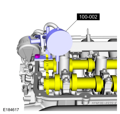
Install the Dial Indicator Gauge with Holding Fixture so
the rounded tip of the dial indicator is on top of the camshaft lobe
and on the same plane as the valve tappet.
 |
-
Rotate the crankshaft using a breaker bar and socket
attached to the crankshaft pulley retainer bolt. Rotate the crankshaft
until the base circle of the camshaft lobe is reached.
-
Zero the dial indicator. Continue to rotate the
crankshaft until the high-lift point of the camshaft lobe is in the
fully raised position (highest indicator reading).
-
To check the accuracy of the original dial indicator
reading, continue to rotate crankshaft until the base circle is reached.
The indicator reading should be zero. If zero reading is not obtained,
repeat Steps 2 through 5.
-
If the lift on any lobe is below specified service
limits, install a new camshaft and camshaft roller followers or valve
tappets.
-
Install the spark plugs.
For additional information, refer to: Spark Plugs (303-07A) .
For additional information, refer to: Spark Plugs (303-07B) .
For additional information, refer to: Spark Plugs (303-07C) .
For additional information, refer to: Spark Plugs (303-07D) .
For additional information, refer to: Spark Plugs (303-07E) .
 Valve Stem Diameter. General Procedures
Check
NOTE:
Refer to the appropriate Section 303-01 for the specification.
Measure the diameter of each intake and exhaust valve
stem at the points shown...
 Electrical
..
Other information:
Lincoln Nautilus 2018-2026 Owners Manual: Changing the Remote Control Battery
WARNING: Keep batteries away from children to prevent ingestion. Failure to follow this instruction could result in personal injury or death. If ingested, immediately seek medical attention. WARNING: If the battery compartment does not securely close, stop using the remote control and replace it as soon as possible. In the meantime, keep the remote control away from children. Failure to f..
Lincoln Nautilus 2018-2026 Service Manual: Rear Quarter Panel Moulding. Removal and Installation
Removal NOTE: LH side shown, RH side similar. NOTE: Removal steps in this procedure may contain installation details. If equipped, remove the pushpins and remove the deflector. Remove the pushpins from the rear of the moulding. NOTICE: To avoid damage to the moulding, only use moderate force. Remove the scr..
Categories
- Manuals Home
- 1st Generation Nautilus Owners Manual
- 1st Generation Nautilus Service Manual
- Auto-Start-Stop
- Anti-Theft Alarm System Settings. Security – Troubleshooting
- Power Outlet - Vehicles With: 110V Power Outlet
- New on site
- Most important about car
Opening and Closing the Hood
Opening the Hood
Copyright © 2026 www.linautilus.com