Lincoln Nautilus: Multifunction Electronic Modules / Body Control Module (BCM). Removal and Installation
Removal
NOTE: Removal steps in this procedure may contain installation details.
-
NOTE: If the BCM did not respond to the diagnostic scan tool, As-Built Data may need to be entered as part of the repair. This step is only necessary if the BCM is being replaced
Using a diagnostic scan tool, begin the PMI process for the BCM following the on-screen instructions.
-
NOTE: The PAM is integral to the BCM . This step is only necessary if the BCM is being replaced.
Using a diagnostic scan tool, begin the PMI process for the PAM following the on-screen instructions.
-
Remove the driver knee airbag.
Refer to: Driver Knee Airbag (501-20B Supplemental Restraint System, Removal and Installation).
-
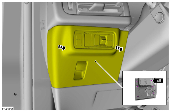
For increased visibility, detach the clips and pivot the instrument panel LH lower trim panel downward.
 |
-
Disconnect the electrical connectors.
.jpg) |
-
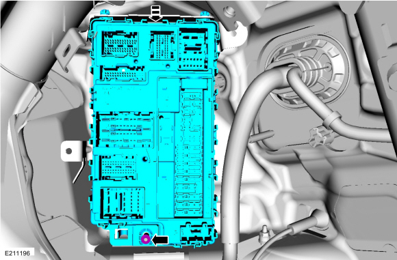
Remove the nut and the BCM .
 |
Installation
-
NOTE: If installing a new BCM , the ignition cannot be turned on until 2 keys are programmed to the vehicle. The BCM still communicates with the diagnostic scan tool with the ignition off. If necessary, use the previous diagnostic scan tool session or start a diagnostic scan tool session using the PCM part number or tear tag number located on the PCM .
NOTE: If installing a new BCM , verify at least 2 of the vehicle keys are available prior to carrying out this procedure.
To install, reverse the removal procedure.
NOTE: Carry out the remaining steps only if installing a new BCM .
-
NOTE: A diagnostic scan tool should not be used to program keys for this specific step.
Program the keys.
-
Place the first key in the backup starting location.
Refer to: Passive Anti-Theft System (PATS) - Component Location (419-01B Passive Anti-Theft System (PATS), Description and Operation).
-
Press the START/STOP button and wait approximately 6 seconds.
-
Press the START/STOP button and remove the first key.
-
Place the second key in the backup starting location.
-
Press the START/STOP button.
-
Place the first key in the backup starting location.
-
Carry out the parameter reset.
Refer to: Anti-Theft Key Programming - Scan Tool (419-01B Passive Anti-Theft System (PATS), General Procedures).
-
Using a diagnostic scan tool, complete the PMI process for the BCM following the on-screen instructions.
-
Using a diagnostic scan tool, carry out the
Configuration Engine Immobilizer (CEI) configuration following the
on-screen instructions (Toolbox > Body > Service Functions >
CEI Lock Configuration).
-
Using a diagnostic scan tool, carry out the battery
monitor sensor reset following the on-screen instructions (Toolbox >
Body > BMS Reset).
-
NOTE: This step does not apply to vehicles equipped with 360 degree camera view.
If equipped with video rear parking aid, using a diagnostic scan tool, carry out the new module initialization following the on-screen instructions (Toolbox > Electrical > Service Functions > LIN New Module Initialization).
-
Configure the customer preference programmable parameters.
Refer to: Module Programming (418-01A Module Configuration, General Procedures).
-
Train the tire pressure sensors.
Refer to: Tire Pressure Monitoring System (TPMS) Sensor Location Calibration (204-04B Tire Pressure Monitoring System (TPMS), General Procedures).
-
Carry out the BCM self-test (must include an on-demand self-test) and
then repeat the self-test to confirm all DTC have been cleared.
-
Using a diagnostic scan tool, complete the PMI process for the PAM following the on-screen instructions.
 Transport Mode Deactivation. General Procedures
Deactivation
NOTE:
After vehicle build, some vehicle modules are set in Transport mode
including the IPC and the BCM . Transport mode reduces battery drain
during longer periods where the vehicle is not used...
 Driver Door Module (DDM). Removal and Installation
Removal
NOTE:
Removal steps in this procedure may contain installation details.
NOTE:
If installing a new module, it is necessary to
upload the module configuration information to the diagnostic scan tool
prior to removing the module...
Other information:
Lincoln Nautilus 2018-2026 Service Manual: Interior Front Door Handle. Removal and Installation
Removal NOTE: LH side shown, RH side similar. Remove the front door trim panel. Refer to: Front Door Trim Panel (501-05 Interior Trim and Ornamentation, Removal and Installation). Remove the interior front door handle. If equipped...
Lincoln Nautilus 2018-2026 Owners Manual: Principle of Operation
MyKey allows you to program keys with restricted driving modes to promote good driving habits. All but one of the keys can be activated with these restricted modes. Any keys that remain unprogrammed are referred to as administrator keys or admin keys...
Categories
- Manuals Home
- 1st Generation Nautilus Owners Manual
- 1st Generation Nautilus Service Manual
- Opening the Liftgate
- Massage Seats
- Autounlock and Autolock
- New on site
- Most important about car
Auto-Start-Stop
What Is Auto-Start-Stop
The system is designed to help reduce fuel consumption and CO2 emissions by stopping the engine when it is idling, for example at traffic lights.
Auto-Start-Stop Precautions
WARNING: Apply the parking brake, shift into park (P), switch the ignition off and remove the key before you leave your vehicle. Failure to follow this instruction could result in personal injury or death.
WARNING: Apply the parking brake, shift into park (P), switch the ignition off and remove the key before you open the hood or have any service or repair work completed. If you do not switch the ignition off, the engine could restart at any time. Failure to follow this instruction could result in personal injury or d