Lincoln Nautilus: Front End Sheet Metal Repairs / Dash Panel. Removal and Installation
Special Tool(s) /
General Equipment
| Scraper for Straight Edges |
| Hot Air Gun |
| 8 mm Drill Bit |
| MIG/MAG Welding Equipment |
| Spot Weld Drill Bit |
| Locking Pliers |
Materials
| Name |
Specification |
Seam Sealer
TA-2-B, 3M™ 08308, LORD Fusor® 803DTM |
-
|
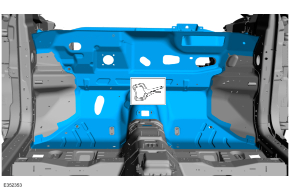
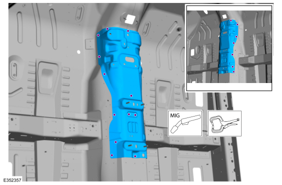
Removal
NOTE:
Roof removed for clarity.
NOTE:
Factory welds may be substituted with resistance or metal
inert gas (MIG) plug welds. Resistance welds may not be placed directly
over original location. They must be placed adjacent to original
location and match factory welds in quantity. Metal inert gas (MIG) plug
welds must equal factory welds in both location and quantity.
NOTE:
Adequately protect all adjacent areas against cutting, grinding and welding procedures.
-
Depower the SRS .
Refer to: Supplemental Restraint System (SRS) Depowering (501-20B Supplemental Restraint System, General Procedures).
-
Remove the windshield glass.
Refer to: Fixed Glass (501-11 Glass, Frames and Mechanisms, General Procedures).
-
If Required:
Dimensionally restore the vehicle to pre-damage condition.
Refer to: Body and Frame (501-26 Body Repairs - Vehicle Specific Information and Tolerance Checks, Description and Operation).
-
If Required:
Remove the engine.
Refer to: Engine (303-01A Engine - 2.0L EcoBoost (184kW/250PS) – MI4, Removal).
Refer to: Engine (303-01B Engine - 2.7L EcoBoost (238kW/324PS), Removal).
-
Remove the hydraulic control unit.
Refer to: Hydraulic Control Unit (HCU) (206-09 Anti-Lock Brake System (ABS) and Stability Control, Removal and Installation).
-
Remove the brake booster and brake pedal and bracket.
Refer to: Brake Booster (206-07 Power Brake Actuation, Removal and Installation).
Refer to: Brake Pedal and Bracket (206-06 Hydraulic Brake Actuation, Removal and Installation).
-
Remove the steering column.
Refer to: Steering Column (211-04 Steering Column, Removal and Installation).
-
Remove the cowl panel.
Refer to: Cowl Panel (501-27 Front End Sheet Metal Repairs, Removal and Installation).
-
Position the carpet, all modules and wiring harnesses away from the working area.
-
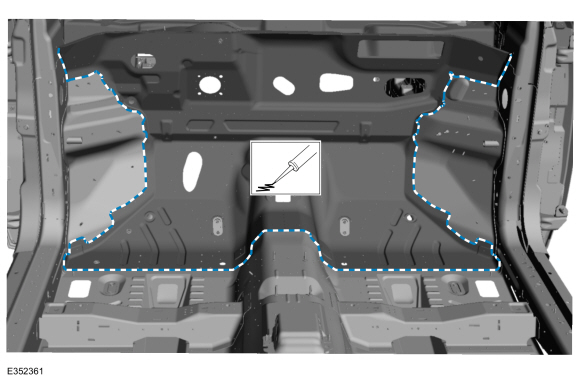
Remove the locally obtained NVH(noise, vibration harshness) mastic pads.
Use the General Equipment: Hot Air Gun
Use the General Equipment: Scraper for Straight Edges
-
Remove the welds and the brake pedal reinforcement.
Use the General Equipment: Spot Weld Drill Bit
-
Remove the welds and the dash lower panel reinforcement.
Use the General Equipment: Spot Weld Drill Bit
-
Remove the welds and the dash center panel.
Use the General Equipment: Spot Weld Drill Bit
-
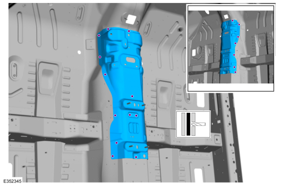
Remove the welds and the transmission tunnel reinforcement.
Use the General Equipment: Spot Weld Drill Bit
-
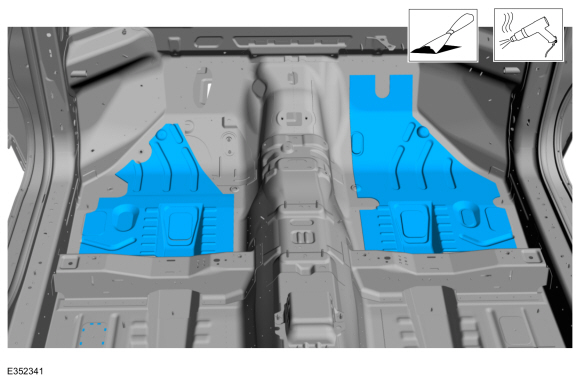
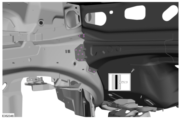
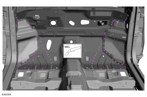
NOTE:
Left hand (LH) side shown, right hand (RH) side similar.
On Both Sides:
Remove the welds.
Use the General Equipment: Spot Weld Drill Bit
-
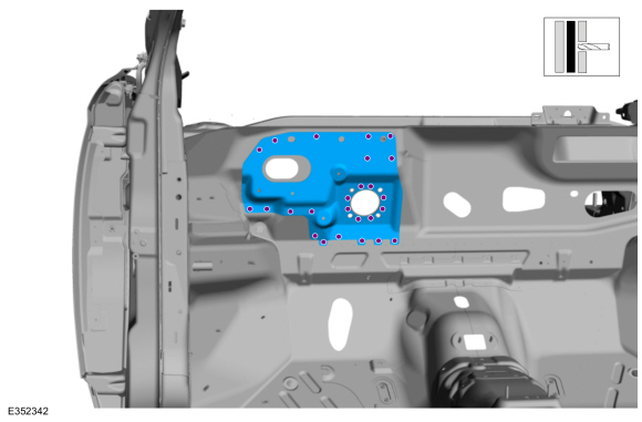
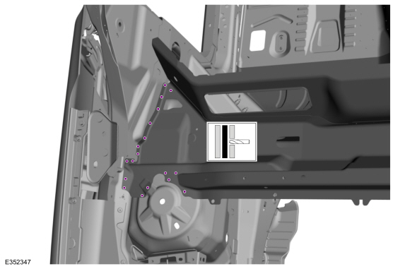
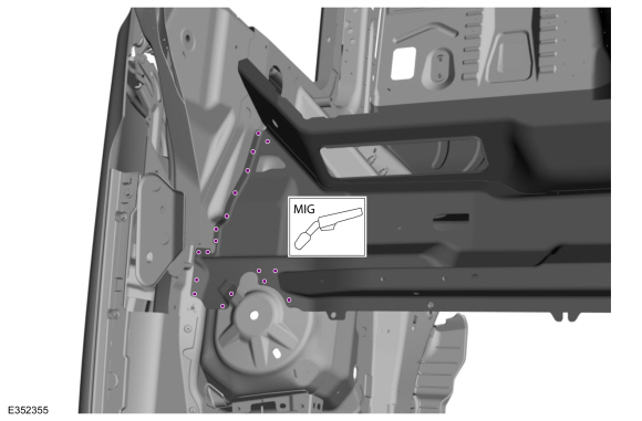
NOTE:
Left hand (LH) side shown, right hand (RH) side similar.
On Both Sides:
Remove the welds.
Use the General Equipment: Spot Weld Drill Bit
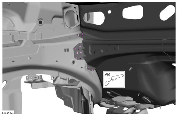
-
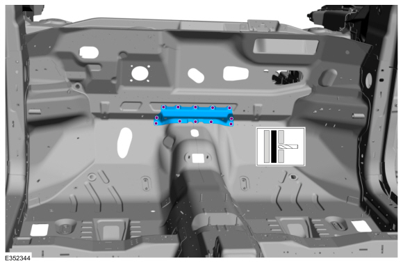
Remove the welds.
Use the General Equipment: Spot Weld Drill Bit
-
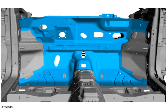
NOTE:
Pay particular attention to the location of noise,
vibration and harshness (NVH) material, adhesive and sealer used to aid
in installation.
Remove the Dash panel.
Installation
NOTE:
Roof removed for clarity.
NOTE:
Factory welds may be substituted with resistance or metal
inert gas (MIG) plug welds. Resistance welds may not be placed directly
over original location. They must be placed adjacent to original
location and match factory welds in quantity. Metal inert gas (MIG) plug
welds must equal factory welds in both location and quantity.
NOTE:
Adequately protect all adjacent areas against cutting, grinding and welding procedures.
-
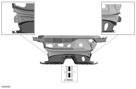
Drill plug weld holes in the replacement dash panel.
Use the General Equipment: 8 mm Drill Bit
-
Drill plug weld holes in the replacement dash panel.
Use the General Equipment: 8 mm Drill Bit
-
Drill plug weld holes in the replacement dash panel.
Use the General Equipment: 8 mm Drill Bit
-
Install, properly position and clamp the replacement dash panel.
Use the General Equipment: Locking Pliers
-
Install the welds.
Use the General Equipment: MIG/MAG Welding Equipment
-
NOTE:
Left hand (LH) side shown, right hand (RH) side similar.
On Both Sides:
Install the welds.
Use the General Equipment: MIG/MAG Welding Equipment
-
NOTE:
Left hand (LH) side shown, right hand (RH) side similar.
On Both Sides:
Install the welds.
Use the General Equipment: MIG/MAG Welding Equipment
-
Install the transmission tunnel reinforcement, properly position, clamp and install the welds.
Use the General Equipment: MIG/MAG Welding Equipment
Use the General Equipment: Locking Pliers
-
Install the dash center panel, properly position, clamp and install the welds.
Use the General Equipment: MIG/MAG Welding Equipment
Use the General Equipment: Locking Pliers
-
Install the lower panel reinforcement, properly position, clamp and install the welds.
Use the General Equipment: MIG/MAG Welding Equipment
Use the General Equipment: Locking Pliers
-
Install brake pedal reinforcement, properly position, clamp and install the welds.
Use the General Equipment: MIG/MAG Welding Equipment
Use the General Equipment: Locking Pliers
-
Dress all welds as required using typical metal finishing techniques and materials.
-
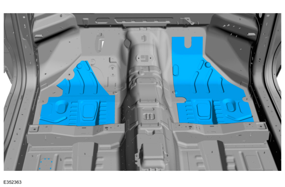
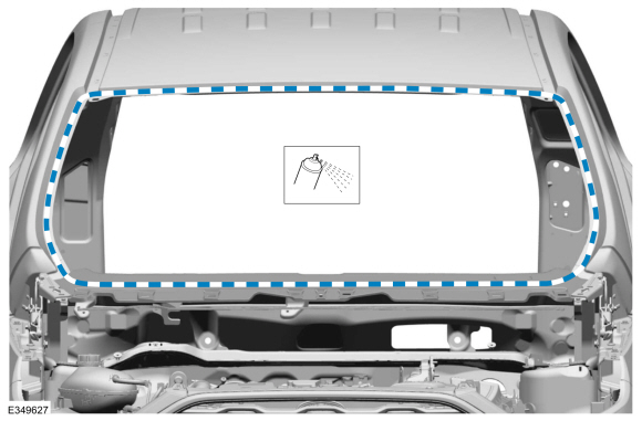
Seam Sealing:
All seams must be sealed to production level.
Material: Seam Sealer
/ TA-2-B, 3M™ 08308, LORD Fusor® 803DTM
-
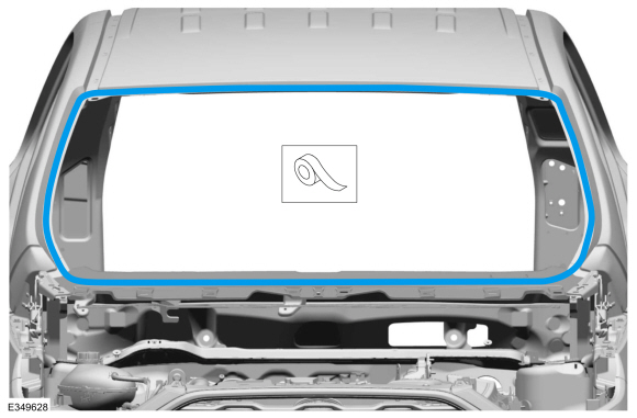
NOTE:
Left hand (LH) side shown, right hand (RH) side similar.
Seam Sealing:
All seams must be sealed to production level.
Material: Seam Sealer
/ TA-2-B, 3M™ 08308, LORD Fusor® 803DTM
-
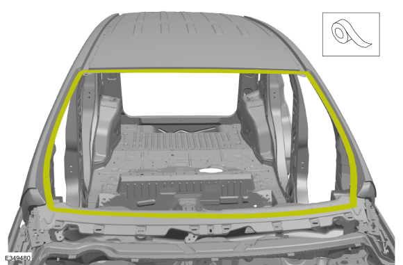
Install the locally obtained NVH(noise, vibration harshness) mastic pads.
-
Install the cowl panel.
Refer to: Cowl Panel (501-27 Front End Sheet Metal Repairs, Removal and Installation).
-
Restore corrosion protection.
Refer to: Corrosion Prevention (501-25 Body Repairs - General Information, General Procedures).
-
Refinish the entire repair using a Ford approved paint system.
-
Sand to remove old adhesive, paint, e-coat and clean.
-
Apply a Ford approved epoxy-based primer and allow to dry.
-
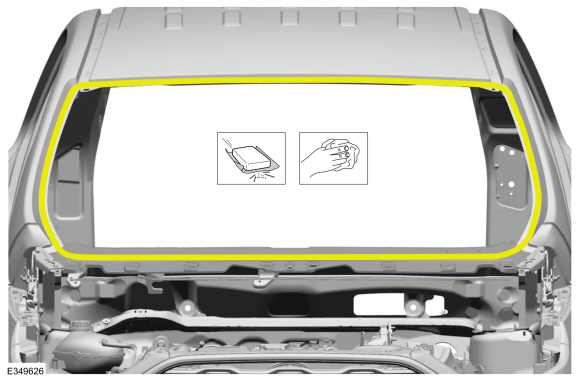
Mask off the windshield opening channel.
-
Refinish the entire repair using a Ford approved paint system.
-
Remove the masking material.
-
Reposition all wiring harnesses, modules and the carpet to original locations.
-
Obtain a new and install the VIN plate.
Refer to: Identification Codes (100-01 Identification Codes, Description and Operation).
-
Install the windshield glass.
Refer to: Fixed Glass (501-11 Glass, Frames and Mechanisms, General Procedures).
-
Install the wiper linkage assembly.
Refer to: Wiper Linkage Assembly (501-16 Wipers and Washers, Removal and Installation).
-
Install the brake booster and brake pedal and bracket.
Refer to: Brake Booster (206-07 Power Brake Actuation, Removal and Installation).
Refer to: Brake Pedal and Bracket (206-06 Hydraulic Brake Actuation, Removal and Installation).
-
Install the hydraulic control unit.
Refer to: Hydraulic Control Unit (HCU) (206-09 Anti-Lock Brake System (ABS) and Stability Control, Removal and Installation).
-
If Required:
Install the engine.
Refer to: Engine (303-01A Engine - 2.0L EcoBoost (184kW/250PS) – MI4, Installation).
Refer to: Engine (303-01B Engine - 2.7L EcoBoost (238kW/324PS), Installation).
-
Install the steering column.
Refer to: Steering Column (211-04 Steering Column, Removal and Installation).
-
Install the instrument panel and console.
Refer to: Instrument Panel (501-12 Instrument Panel and Console, Removal and Installation).
Refer to: Floor Console (501-12 Instrument Panel and Console, Removal and Installation).
-
On Both Sides:
Install the front seat.
Refer to: Front Seat (501-10A Front Seats, Removal and Installation).
-
Install and align the hood.
Refer to: Hood (501-02 Front End Body Panels, Removal and Installation).
Refer to: Hood Alignment (501-03 Body Closures, General Procedures).
-
Repower the SRS.
Refer to: Supplemental Restraint System (SRS) Repowering (501-20B Supplemental Restraint System, General Procedures).
Special Tool(s) /
General Equipment
Resistance Spotwelding Equipment
8 mm Drill Bit
MIG/MAG Welding Equipment
Spot Weld Drill Bit
Locking Pliers
Materials
Name
Specification
Seam SealerTA-2-B, 3M™ 08308, LORD Fusor® 803DTM
-
Removal
NOTE:
Factory welds may be substituted with resistance or metal
inert gas (MIG) plug welds...
Special Tool(s) /
General Equipment
Resistance Spotwelding Equipment
Scraper for Straight Edges
Hot Air Gun
8 mm Drill Bit
MIG/MAG Welding Equipment
Spot Weld Drill Bit
Locking Pliers
Materials
Name
Specification
Seam SealerTA-2-B, 3M™ 08308, LORD Fusor® 803DTM
-
Removal
NOTE:
LH side shown, RH side similar...
Other information:
Item
Description
1
Driver and passenger C-pillar side impact sensors
2
Driver front door side impact sensor
3
Clockspring
4
PAD indicator
5
RCM
6
OCSM (includes OCS sensor and gel-filled bladder)
7
Passenger front door side impact sensor
8
Seat position sensors
9
LH and RH front impact severity sensors
..
General Specifications
NOTE:
Measurements listed at curb load. Curb load is defined as
"full service fluids, full fuel tank(s), no passengers and no cargo".
Item
Specification
Ball Joint Deflection
Lower
0.0 mm (0.0 in) - 0.2 mm (0.0079 in)
Ride Height
Front — (AWD and FWD - Vehicles with 21 inch whe..
.jpg)
.jpg)
.jpg)
.jpg)
.jpg)
.jpg)

.jpg)
 Cowl Panel. Removal and Installation
 Fender Apron Panel. Removal and Installation