Lincoln Nautilus Manuals

Lincoln Nautilus: Voltage Converter/Inverter / Direct Current/Direct Current (DC/DC) Converter Control Module. Diagnosis and Testing

Lincoln Nautilus 2018-2024 Service Manual / Electrical / Battery and Charging System / Voltage Converter/Inverter / Direct Current/Direct Current (DC/DC) Converter Control Module. Diagnosis and Testing

Diagnostics in this manual assume a certain skill level and knowledge of Ford-specific diagnostic practices.
REFER to: Diagnostic Methods (100-00 General Information, Description and Operation).


  Direct Current/Direct Current (DC/DC) Converter Control Module DTC Chart


DTC Description Action
P0A12:11 DC/DC Converter Enable Circuit Low: Circuit Short To Ground   GO to Pinpoint Test A
P1661:13 Output Circuit Check Circuit Low: Circuit Open This DTC is informational only and sets during a self test if the output current is less than 2 amps. DIAGNOSE all other Direct Current/Direct Current (DC/DC) Diagnostic Trouble Codes (DTCs) first. If no other Diagnostic Trouble Codes (DTCs) are present check for pushed out pins, open circuits, fuses, or disconnected electrical loads that pass through the Direct Current/Direct Current (DC/DC) Converter Control Module. REFER to the Wiring Diagrams manual to identify the possible causes of the open circuits or disconnected electrical loads.
B1310:11 Run/Start Control: Circuit Short To Ground   GO to Pinpoint Test B
B1310:15 Run/Start Control: Circuit Short To Battery or Open   GO to Pinpoint Test C
U0100:87 Lost Communication With ECM/PCM "A": Missing Message   GO to Pinpoint Test E
U1000:00 Solid State Driver Protection Active - Driver Disabled: No Sub Type Information   GO to Pinpoint Test D
U2014:04 Control Module Hardware: System Internal Failure ADDRESS all other Diagnostic Trouble Codes (DTCs) first. CLEAR the Diagnostic Trouble Codes (DTCs). REPEAT the self-test. If DTC U2014:04 is retrieved again, INSTALL a new Direct Current/Direct Current (DC/DC) converter control module.
REFER to: Direct Current/Direct Current (DC/DC) Converter Control Module (414-05 Voltage Converter/Inverter, Removal and Installation).
U2100:00 Initial Configuration Not Complete: No Sub Type Information This DTC will be present in a new service replacement module. CARRY OUT PMI on the Direct Current/Direct Current (DC/DC) converter control module.
REFER to: Module Configuration (418-01 Module Configuration) .
U3000:49 Control Module: Internal Electronic Failure ADDRESS all other Diagnostic Trouble Codes (DTCs) first. CLEAR the Diagnostic Trouble Codes (DTCs). REPEAT the self-test. If DTC U3000:49 is retrieved again, INSTALL a new Direct Current/Direct Current (DC/DC) converter control module.
REFER to: Direct Current/Direct Current (DC/DC) Converter Control Module (414-05 Voltage Converter/Inverter, Removal and Installation).

Symptom Chart

Symptom Possible Sources Action
  • A module does not respond to the scan tool
  • Fuse(s)
  • 12-volt battery
  • Module Ground
  • Relay
  • Wiring, terminals or connectors
  • Direct Current/Direct Current (DC/DC) converter control module
  • Perform symptom diagnostics.
    REFER to: Communications Network (418-00 Module Communications Network) .
  • The start/stop function is inoperative and disabled
  • System operation criteria not met.

  • REFER to: Starting System - System Operation and Component Description (303-06A Starting System - 2.0L EcoBoost (184kW/250PS) – MI4, Description and Operation).
  • 12-volt battery

  • REFER to: Battery (414-01 Battery, Mounting and Cables, Diagnosis and Testing).
  • Fuse(s)
  • Direct Current/Direct Current (DC/DC) converter control module
  • Wiring, terminals or connectors

  • REFER to: Starting System (303-06A Starting System - 2.0L EcoBoost (184kW/250PS) – MI4, Diagnosis and Testing).

Pinpoint Test(s)

P0A12:11


Refer to Wiring Diagrams Cell 40 for schematic and connector information.

Normal Operation and Fault Conditions

During an auto-start-stop event, the PCM sends a voltage signal to the Direct Current/Direct Current (DC/DC) converter control module through the boost enable circuit. If the PCM boost enable circuit becomes shorted to ground, or is low for more than 60 seconds DTC P0A12:11 sets and the Direct Current/Direct Current (DC/DC) converter control module will not boost. If the enable circuit becomes open, the Direct Current/Direct Current (DC/DC) converter control module will not receive a re-crank signal from the PCM and the Direct Current/Direct Current (DC/DC) converter control module will not boost. Any systems powered through the Direct Current/Direct Current (DC/DC) converter control module may restart during an auto-start-stop event. For more information on the auto-start-stop system,
REFER to: Starting System - System Operation and Component Description (303-06A Starting System - 2.0L EcoBoost (184kW/250PS) – MI4, Description and Operation).


  Diagnostic Trouble Code (DTC) Fault Trigger Conditions


DTC Description Fault Trigger Conditions
P0A12:11 DC/DC Converter Enable Circuit Low: Circuit Short To Ground Sets in the Direct Current/Direct Current (DC/DC) converter control module when the DC/DC Converter Enable Circuit from the PCM is low for more than 60 seconds.

Possible Sources

  • Direct Current/Direct Current (DC/DC) converter control module
  • PCM
  • Wiring, terminals or connectors

PINPOINT TEST A: P0A12:11
NOTE: Use the correct probe adapter(s) from the Flex Probe Kit when taking measurements. Failure to use the correct probe adapter(s) may damage the connector.
A1 CHECK DIRECT CURRENT/DIRECT CURRENT (DC/DC) CONVERTER ENABLE CIRCUIT FOR A SHORT TO VOLTAGE
  • Ignition OFF.
  • Disconnect Low Voltage Direct Current/Direct Current (DC/DC) converter C2513 .
  • Disconnect PCM C1381B (2.0L EcoBoost).
  • Disconnect PCM C1551B (2.7L EcoBoost).
  • Ignition ON.
  • Measure:
    Click to display connectors
    Positive Lead Measurement / Action Negative Lead
      C2513-2   Ground

Is any voltage present?
Yes REPAIR the circuit.
No GO to A2

A2 CHECK DIRECT CURRENT/DIRECT CURRENT (DC/DC) CONVERTER ENABLE CIRCUIT FOR A SHORT TO GROUND
  • Ignition OFF.
  • Measure:
    Click to display connectors
    Positive Lead Measurement / Action Negative Lead
      C2513-2   Ground

Is the resistance greater than 10,000 ohms?
Yes GO to A3
No REPAIR the circuit.

A3 CHECK DIRECT CURRENT/DIRECT CURRENT (DC/DC) CONVERTER ENABLE CIRCUIT FOR AN OPEN
  • Measure:
    Click to display connectors

      For 2.0L EcoBoost


    Positive Lead Measurement / Action Negative Lead
      C2513-2   C1381B-68

    Click to display connectors

      For 2.7L EcoBoost


    Positive Lead Measurement / Action Negative Lead
      C2513-2   C1551B-49

Is the resistance less than 3 ohms?
Yes GO to A4
No REPAIR the circuit.

A4 PERFORM THE PCM (POWERTRAIN CONTROL MODULE) SELF TEST
  • Connect PCM C1381B (2.0L EcoBoost).
  • Connect PCM C1551B (2.7L EcoBoost).
  • Connect Low Voltage Direct Current/Direct Current (DC/DC) converter C2513 .
  • Ignition ON.
  • Using a diagnostic scan tool, perform the PCM self-test.

Are any PCM Diagnostic Trouble Codes (DTCs) present?
Yes For DTC U0298:00, DIAGNOSE the network communication concern.
REFER to: Communications Network (418-00 Module Communications Network) . For all other PCM Diagnostic Trouble Codes (DTCs),
REFER to: Electronic Engine Controls (303-14 Electronic Engine Controls) .
No GO to A5

A5 CHECK DIRECT CURRENT/DIRECT CURRENT (DC/DC) CONVERTER DIAGNOSTIC TROUBLE CODES (DTCS) WITH THE PCM (POWERTRAIN CONTROL MODULE) DISCONNECTED
  • Disconnect PCM C1381B (2.0L EcoBoost).
  • Disconnect PCM C1551B (2.7L EcoBoost).
  • Ignition ON.
  • Using a diagnostic scan tool, clear the Low Voltage Direct Current/Direct Current (DC/DC) converter Diagnostic Trouble Codes (DTCs).
  • Using a diagnostic scan tool, perform the Low Voltage Direct Current/Direct Current (DC/DC) converter self-test.

Is DTC P0A12:11 retrieved?
Yes GO to A6
No GO to A7

A6 CHECK FOR CORRECT DIRECT CURRENT/DIRECT CURRENT (DC/DC) CONVERTER OPERATION
  • Ignition OFF.
  • Disconnect Direct Current/Direct Current (DC/DC) converter control module C2513 .
  • Inspect and repair:
    • corrosion (install new connector or terminals – clean module pins)
    • damaged or bent pins – install new terminals/pins
    • pushed-out pins – install new pins as necessary
  • Reconnect all connectors. Make sure they seat and latch correctly.
  • Operate the system and determine if the concern is still present.

Is the concern still present?
Yes CHECK OASIS for any applicable Technical Service Bulletins (TSBs). If a TSB exists for this concern, discontinue this test and follow TSB instructions. If no Technical Service Bulletins (TSBs) address this concern, INSTALL a new Direct Current/Direct Current (DC/DC) converter control module.
REFER to: Direct Current/Direct Current (DC/DC) Converter Control Module (414-05 Voltage Converter/Inverter, Removal and Installation).
No The system is operating correctly at this time. The concern may have been caused by module connections. Address the root cause of any connector or pin issues.

A7 CHECK FOR CORRECT PCM (POWERTRAIN CONTROL MODULE) OPERATION
  • Ignition OFF.
  • Disconnect and inspect all PCM connectors.
  • Repair:
    • corrosion (install new connector or terminals – clean module pins)
    • damaged or bent pins – install new terminals/pins
    • pushed-out pins – install new pins as necessary
  • Reconnect all connectors. Make sure they seat and latch correctly.
  • Operate the system and determine if the concern is still present.

Is the concern still present?
Yes CHECK OASIS for any applicable Technical Service Bulletins (TSBs). If a TSB exists for this concern, discontinue this test and follow TSB instructions. If no Technical Service Bulletins (TSBs) address this concern,
   Click here to access Guided Routine (PCM).
No The system is operating correctly at this time. The concern may have been caused by module connections. Address the root cause of any connector or pin issues.


B1310:11


Refer to Wiring Diagrams Cell 40 for schematic and connector information.

Normal Operation and Fault Conditions

The Direct Current/Direct Current (DC/DC) converter control module measures the current draw on the run/start switched output circuit. If the Direct Current/Direct Current (DC/DC) converter control module detects a short to ground or if the current draw exceeds 8 amps the DTC B1310:11 sets and the switching transistor is disabled for the current ignition cycle. A excessive number of shorts to ground or current draw events will set DTC U1000:00 and the switching transistor is disabled until it is reset using a diagnostic scan tool. Presence of this DTC may result in the blind spot detection and video camera being inoperative.


  DTC Fault Trigger Conditions


DTC Description Fault Trigger Conditions
B1310:11 Run/Start Control: Circuit Short To Ground Sets in the Direct Current/Direct Current (DC/DC) converter control module when the run/start switched output circuit is shorted to ground or when the current exceeds 8 amps.

Possible Sources

  • Direct Current/Direct Current (DC/DC) converter control module
  • CADS (collision avoidance detection system module)
  • IPMB
  • Front Parking Aid Camera
  • Rear Parking Aid Camera
  • SODL
  • SODR
  • Wiring, terminals or connectors

PINPOINT TEST B: B1310:11
NOTE: Use the correct probe adapter(s) from the Flex Probe Kit when taking measurements. Failure to use the correct probe adapter(s) may damage the connector.
B1 CHECK THE DIRECT CURRENT/DIRECT CURRENT (DC/DC) CONVERTER RUN/START OUTPUT CIRCUIT FOR A SHORT TO GROUND
  • Ignition OFF.
  • Disconnect DCDC C2513 .
  • Disconnect CADS (collision avoidance detection system module) C1897 (if equipped).
  • Disconnect SODL C4369 (if equipped).
  • Disconnect SODR C4370 (if equipped).
  • Disconnect IPMB C3676A (if equipped).
  • Disconnect Front Park Assist Camera C1663 (if equipped).
  • Disconnect Rear Park Assist Camera C4357 (if equipped).
  • Measure:
    Click to display connectors
    Positive Lead Measurement / Action Negative Lead
      C2513-5   Ground

Is the resistance greater than 10,000 ohms?
Yes CONNECT Direct Current/Direct Current (DC/DC) converter control module C2513
GO to B2
No REPAIR the circuit.

B2 CHECK FOR A SHORTED DIRECT CURRENT/DIRECT CURRENT (DC/DC) CONVERTER
  • Ignition OFF.
  • Connect DIRECT CURRENT/DIRECT CURRENT (DC/DC) CONVERTER C2513 .
  • Ignition ON.
  • Using a diagnostic scan tool, clear the Direct Current/Direct Current (DC/DC) converter control module Diagnostic Trouble Codes (DTCs).
  • Using a diagnostic scan tool, perform Direct Current/Direct Current (DC/DC) converter control module self-test.

Is DTC B1310:11 present?
Yes INSTALL a new Direct Current/Direct Current (DC/DC) converter control module.
REFER to: Direct Current/Direct Current (DC/DC) Converter Control Module (414-05 Voltage Converter/Inverter, Removal and Installation).
No GO to B3

B3 CHECK FOR A SHORTED CADS
  • If not equipped with a collision avoidance detection system, go to step B4.
  • Ignition OFF.
  • Connect CADS (collision avoidance detection system module) C1897 .
  • Ignition ON.
  • Using a diagnostic scan tool, clear the Direct Current/Direct Current (DC/DC) converter control module Diagnostic Trouble Codes (DTCs).
  • Using a diagnostic scan tool, perform Direct Current/Direct Current (DC/DC) converter control module self-test.

Is DTC B1310:11 present?
Yes INSTALL a new CADS (collision avoidance detection system module). REFER to: Collision Avoidance Detection System Module (CADS) (419-03 Collision Warning and Collision Avoidance System, Removal and Installation).
No GO to B4

B4 CHECK FOR A SHORTED SODL (SIDE OBSTACLE DETECTION CONTROL MODULE LH)
  • If not equipped with BLIS , go to step B6.
  • Ignition OFF.
  • Connect SODL C4369 .
  • Ignition ON.
  • Using a diagnostic scan tool, clear the Direct Current/Direct Current (DC/DC) converter control module Diagnostic Trouble Codes (DTCs).
  • Using a diagnostic scan tool, perform Direct Current/Direct Current (DC/DC) converter control module self-test.

Is DTC B1310:11 present?
Yes INSTALL a new SODL .
REFER to: Side Obstacle Detection Control Module (SODCM) (419-04 Side and Rear Vision, Removal and Installation).
No GO to B5

B5 CHECK FOR A SHORTED SODR (SIDE OBSTACLE DETECTION CONTROL MODULE RH)
  • Ignition OFF.
  • Connect SODR C4370 .
  • Ignition ON.
  • Using a diagnostic scan tool, clear the Direct Current/Direct Current (DC/DC) converter control module Diagnostic Trouble Codes (DTCs).
  • Using a diagnostic scan tool, perform Direct Current/Direct Current (DC/DC) converter control module self-test.

Is DTC B1310:11 present?
Yes INSTALL a new
REFER to: Side Obstacle Detection Control Module (SODCM) (419-04 Side and Rear Vision, Removal and Installation).
No GO to B6

B6 CHECK FOR A SHORTED IPMB (IMAGE PROCESSING MODULE B)
  • If not equipped with Parking Aid Camera, go to step B9.
  • Ignition OFF.
  • Connect IPMB C3676A .
  • Ignition ON.
  • Using a diagnostic scan tool, clear the Direct Current/Direct Current (DC/DC) converter control module Diagnostic Trouble Codes (DTCs).
  • Using a diagnostic scan tool, perform Direct Current/Direct Current (DC/DC) converter control module self-test.

Is DTC B1310:11 present?
Yes INSTALL a new IPMB .
REFER to: Image Processing Module B (IPMB) (413-13B Parking Aid - Vehicles With: Parking Aid Camera, Removal and Installation).
No GO to B7

B7 CHECK FOR A SHORTED FRONT PARKING AID CAMERA
  • Ignition OFF.
  • Connect Front Parking Aid Camera C1663 .
  • Ignition ON.
  • Using a diagnostic scan tool, clear the Direct Current/Direct Current (DC/DC) converter control module Diagnostic Trouble Codes (DTCs).
  • Using a diagnostic scan tool, perform Direct Current/Direct Current (DC/DC) converter control module self-test.

Is DTC B1310:11 present?
Yes INSTALL a new Front Parking Aid Camera.
REFER to: Front Parking Aid Camera (413-13B Parking Aid - Vehicles With: Parking Aid Camera, Removal and Installation).
No GO to B8

B8 CHECK FOR A SHORTED REAR PARK ASSIST CAMERA
  • Ignition OFF.
  • Connect Rear Park Assist Camera C4357 .
  • Ignition ON.
  • Using a diagnostic scan tool, clear the Direct Current/Direct Current (DC/DC) converter control module Diagnostic Trouble Codes (DTCs).
  • Using a diagnostic scan tool, perform Direct Current/Direct Current (DC/DC) converter control module self-test.

Is DTC B1310:11 present?
Yes INSTALL a new Rear Park Assist Camera.
REFER to: Rear Parking Aid Camera (413-13B Parking Aid - Vehicles With: Parking Aid Camera, Removal and Installation).
No GO to B9

B9 CHECK FOR CORRECT DIRECT CURRENT/DIRECT CURRENT (DC/DC) CONVERTER OPERATION
  • Ignition OFF.
  • Disconnect Direct Current/Direct Current (DC/DC) converter control module C2513 .
  • Inspect and repair:
    • corrosion (install new connector or terminals – clean module pins)
    • damaged or bent pins – install new terminals/pins
    • pushed-out pins – install new pins as necessary
  • Reconnect all connectors. Make sure they seat and latch correctly.
  • Operate the system and determine if the concern is still present.

Is the concern still present?
Yes CHECK OASIS for any applicable Technical Service Bulletins (TSBs). If a TSB exists for this concern, discontinue this test and follow TSB instructions. If no Technical Service Bulletins (TSBs) address this concern, INSTALL a new Direct Current/Direct Current (DC/DC) converter control module.
REFER to: Direct Current/Direct Current (DC/DC) Converter Control Module (414-05 Voltage Converter/Inverter, Removal and Installation).
No The system is operating correctly at this time. The concern may have been caused by module connections. Address the root cause of any connector or pin issues.


B1310:15


Refer to Wiring Diagrams Cell 40 for schematic and connector information.

Normal Operation and Fault Conditions

The Direct Current/Direct Current (DC/DC) converter control module measures the current draw on the run/start switched output circuit. If the current draw is less than expected this indicates the circuit is shorted to battery or open. If a failure is present during Direct Current/Direct Current (DC/DC) converter control module initialization at key on it is disabled until the next ignition cycle. Presence of this DTC may result in the blind spot detection and video camera module being inoperative.


  DTC Fault Trigger Conditions


DTC Description Fault Trigger Conditions
B1310:15 Run/Start Control: Circuit Short To Battery or Open Sets in the Direct Current/Direct Current (DC/DC) converter control module when the run/start switched output circuit current is less than expected.

Possible Sources

  • Direct Current/Direct Current (DC/DC) converter control module
  • Wiring, terminals or connectors

PINPOINT TEST C: B1310:15
NOTE: Use the correct probe adapter(s) from the Flex Probe Kit when taking measurements. Failure to use the correct probe adapter(s) may damage the connector.
C1 CHECK THE DIRECT CURRENT/DIRECT CURRENT (DC/DC) CONVERTER RUN/START CIRCUIT FOR A SHORT TO VOLTAGE
  • Ignition OFF.
  • Disconnect DCDC C2513 .
  • Disconnect CADS (collision avoidance detection system module) C1897 (if equipped).
  • Disconnect SODL C4369 (if equipped).
  • Disconnect SODR C4370 (if equipped).
  • Disconnect IPMB C3676A (if equipped).
  • Disconnect Front Park Assist Camera C1663 (if equipped).
  • Disconnect Rear Park Assist Camera C4357 (if equipped).
  • Ignition ON.
  • Measure:
    Click to display connectors
    Positive Lead Measurement / Action Negative Lead
      C2513-5   Ground

Is there any voltage present?
Yes REPAIR the circuit.
No GO to C2

C2 CHECK FOR A SHORTED CADS
  • If not equipped with collision avoidance detection system, go to step B6.
  • Ignition OFF.
  • Connect CADS (collision avoidance detection system module) C1897 .
  • Ignition ON.
  • Using a diagnostic scan tool, clear the Direct Current/Direct Current (DC/DC) converter control module Diagnostic Trouble Codes (DTCs).
  • Using a diagnostic scan tool, perform Direct Current/Direct Current (DC/DC) converter control module self-test.

Is DTC B1310:15 present?
Yes INSTALL a new CADS (collision avoidance detection system module) REFER to: Collision Avoidance Detection System Module (CADS) (419-03 Collision Warning and Collision Avoidance System, Removal and Installation).
No GO to C3

C3 CHECK FOR A SHORTED SODL (SIDE OBSTACLE DETECTION CONTROL MODULE LH)
  • If not equipped with BLIS , go to step C8.
  • Ignition OFF.
  • Connect SODL C4369 .
  • Ignition ON.
  • Using a diagnostic scan tool, clear the Direct Current/Direct Current (DC/DC) converter control module Diagnostic Trouble Codes (DTCs).
  • Using a diagnostic scan tool, perform Direct Current/Direct Current (DC/DC) converter control module self-test.

Is DTC B1310:15 present?
Yes INSTALL a newSODL .
REFER to: Side Obstacle Detection Control Module (SODCM) (419-04 Side and Rear Vision, Removal and Installation).
No GO to C4

C4 CHECK FOR A SHORTED SODR (SIDE OBSTACLE DETECTION CONTROL MODULE RH)
  • Ignition OFF.
  • Connect SODR C4370 .
  • Ignition ON.
  • Using a diagnostic scan tool, clear the Direct Current/Direct Current (DC/DC) converter control module Diagnostic Trouble Codes (DTCs).
  • Using a diagnostic scan tool, perform Direct Current/Direct Current (DC/DC) converter control module self-test.

Is DTC B1310:15 present?
Yes INSTALL a new SODR .
REFER to: Side Obstacle Detection Control Module (SODCM) (419-04 Side and Rear Vision, Removal and Installation).
No GO to C5

C5 CHECK FOR A SHORTED IPMB (IMAGE PROCESSING MODULE B)
  • If not equipped with Parking Aid Camera, go to step B11.
  • Ignition OFF.
  • Connect IPMB C3676A .
  • Ignition ON.
  • Using a diagnostic scan tool, clear the Direct Current/Direct Current (DC/DC) converter control module Diagnostic Trouble Codes (DTCs).
  • Using a diagnostic scan tool, perform Direct Current/Direct Current (DC/DC) converter control module self-test.

Is DTC B1310:15 present?
Yes INSTALL a new IPMB .
REFER to: Image Processing Module B (IPMB) (413-13B Parking Aid - Vehicles With: Parking Aid Camera, Removal and Installation).
No GO to C6

C6 CHECK FOR A SHORTED FRONT PARKING AID CAMERA
  • Ignition OFF.
  • Connect Front Parking Aid Camera C1663 .
  • Ignition ON.
  • Using a diagnostic scan tool, clear the Direct Current/Direct Current (DC/DC) converter control module Diagnostic Trouble Codes (DTCs).
  • Using a diagnostic scan tool, perform Direct Current/Direct Current (DC/DC) converter control module self-test.

Is DTC B1310:15 present?
Yes INSTALL a new Front Parking Aid Camera.
REFER to: Front Parking Aid Camera (413-13B Parking Aid - Vehicles With: Parking Aid Camera, Removal and Installation).
No GO to C7

C7 CHECK FOR A SHORTED REAR PARK ASSIST CAMERA
  • Ignition OFF.
  • Connect Rear Park Assist Camera C4357 .
  • Ignition ON.
  • Using a diagnostic scan tool, clear the Direct Current/Direct Current (DC/DC) converter control module Diagnostic Trouble Codes (DTCs).
  • Using a diagnostic scan tool, perform Direct Current/Direct Current (DC/DC) converter control module self-test.

Is DTC B1310:15 present?
Yes INSTALL a new Rear Park Assist Camera.
REFER to: Rear Parking Aid Camera (413-13B Parking Aid - Vehicles With: Parking Aid Camera, Removal and Installation).
No GO to C8

C8 CHECK FOR CORRECT DIRECT CURRENT/DIRECT CURRENT (DC/DC) CONVERTER OPERATION
  • Ignition OFF.
  • Disconnect Direct Current/Direct Current (DC/DC) converter control module C2513 .
  • Inspect and repair:
    • corrosion (install new connector or terminals – clean module pins)
    • damaged or bent pins – install new terminals/pins
    • pushed-out pins – install new pins as necessary
  • Reconnect all connectors. Make sure they seat and latch correctly.
  • Operate the system and determine if the concern is still present.

Is the concern still present?
Yes CHECK OASIS for any applicable Technical Service Bulletins (TSBs). If a TSB exists for this concern, discontinue this test and follow TSB instructions. If no Technical Service Bulletins (TSBs) address this concern, INSTALL a new Direct Current/Direct Current (DC/DC) converter control module.
REFER to: Direct Current/Direct Current (DC/DC) Converter Control Module (414-05 Voltage Converter/Inverter, Removal and Installation).
No The system is operating correctly at this time. The concern may have been caused by module connections. Address the root cause of any connector or pin issues.


U1000:00


Refer to Wiring Diagrams Cell 13 for schematic and connector information.

Normal Operation and Fault Conditions

The Direct Current/Direct Current (DC/DC) converter control module measures the current draw on the run/start switched output circuit on pin 5. If the Direct Current/Direct Current (DC/DC) converter control module detects a short to ground the switching transistor is disabled for the current ignition cycle. An excessive number of shorts to ground or current draw events will set DTC U1000:00 and the switching transistor will be disabled until it is reset using a diagnostic scan tool. Presence of this DTC may result in the blind spot detection and video camera being inoperative.


  DTC Fault Trigger Conditions


DTC Description Fault Trigger Conditions
U1000:00 Solid State Driver Protection Active - Driver Disabled: No Sub Type Information Sets in the Direct Current/Direct Current (DC/DC) converter control module when an excessive number of run/start control circuit short to ground events have occurred.

Possible Sources

  • Direct Current/Direct Current (DC/DC) converter control module
  • Wiring, terminals or connectors

PINPOINT TEST D: U1000:00
D1 REVIEW THE DIAGNOSTIC TROUBLE CODES (DTCS)
  • Review the Diagnostic Trouble Codes (DTCs) from the Direct Current/Direct Current (DC/DC) converter control module self-test.

Are any other Diagnostic Trouble Codes (DTCs) present, besides U1000:00 or U3000:49?
Yes REFER to the Direct Current/Direct Current (DC/DC) converter control module DTC chart in this section.
No GO to D2

D2 REPEAT THE DIRECT CURRENT/DIRECT CURRENT (DC/DC) CONVERTER SELF-TEST
  • Ignition ON.
  • Using a diagnostic scan tool, clear the Direct Current/Direct Current (DC/DC) converter control module Diagnostic Trouble Codes (DTCs).
  • Using a diagnostic scan tool, perform the Direct Current/Direct Current (DC/DC) converter control module self-test.

Is DTC U3000:49 present?
Yes INSTALL a new Direct Current/Direct Current (DC/DC) converter control module.
REFER to: Direct Current/Direct Current (DC/DC) Converter Control Module (414-05 Voltage Converter/Inverter, Removal and Installation).
No The system is operating correctly at this time. The circuit short has been repaired.


U0100:87


Refer to Wiring Diagrams Cell 40 for schematic and connector information.

Normal Operation and Fault Conditions

The Direct Current/Direct Current (DC/DC) converter control module communicates with the PCM over a High Speed Controller Area Network (HS-CAN) to send and receive important vehicle data.

When powered on, the Direct Current/Direct Current (DC/DC) converter control module continually monitors the High Speed Controller Area Network (HS-CAN). If communication with a module is lost, the Direct Current/Direct Current (DC/DC) converter control module sets the appropriate DTC .

Possible Sources

  • Network traffic
  • Direct Current/Direct Current (DC/DC) converter control module
  • PCM

  DTC Fault Trigger Conditions


DTC Description Fault Trigger Conditions
U0100:87 Lost Communication With ECM/PCM "A": Missing Message This DTC sets if the Direct Current/Direct Current (DC/DC) converter control module does not receive an expected message from the PCM .

PINPOINT TEST E: U0100:87
E1 CHECK THE COMMUNICATION NETWORK
  • Ignition ON.
  • Using a diagnostic scan tool, perform a network test.

Does the PCM pass the network test?
Yes GO to E2
No DIAGNOSE the scan tool communication with the PCM concern.
REFER to: Communications Network (418-00 Module Communications Network) .

E2 CHECK THE DIRECT CURRENT/DIRECT CURRENT (DC/DC) CONVERTER CONTINUOUS MEMORY DIAGNOSTIC TROUBLE CODES (CMDTCS)
  • Using a diagnostic scan tool, perform the Direct Current/Direct Current (DC/DC) converter control module self-test.
  • Using a diagnostic scan tool, clear the Direct Current/Direct Current (DC/DC) converter control module Diagnostic Trouble Codes (DTCs).
  • Wait 10 seconds.
  • Using a diagnostic scan tool, perform the Direct Current/Direct Current (DC/DC) converter control module self-test.

Is DTC U0100:87 retrieved?
Yes GO to E3
No The system is operating correctly at this time. The DTC may have been set due to high network traffic or an intermittent fault condition.

E3 RETRIEVE THE DIAGNOSTIC TROUBLE CODES (DTCS) FROM THE PCM (POWERTRAIN CONTROL MODULE)
  • Using a diagnostic scan tool, perform the PCM self-test.

Is DTC P0562:00 or P0563:00 recorded?
Yes DIAGNOSE the PCM DTC .
REFER to: Electronic Engine Controls (303-14 Electronic Engine Controls) .
No GO to E4

E4 CHECK FOR A LOST COMMUNICATION WITH THE PCM (POWERTRAIN CONTROL MODULE) IN OTHER MODULES
  • Using a diagnostic scan tool, retrieve Continuous Memory Diagnostic Trouble Codes (CMDTCs) from all modules.

Is DTC U0100:00 or U0100:87 set in multiple modules?
Yes CHECK OASIS for any applicable Technical Service Bulletins (TSBs). If a TSB exists for this concern, discontinue this test and follow TSB instructions. If no Technical Service Bulletins (TSBs) address this concern,
   Click here to access Guided Routine (PCM).
No CHECK OASIS for any applicable Technical Service Bulletins (TSBs). If a TSB exists for this concern, discontinue this test and follow TSB instructions. If no Technical Service Bulletins (TSBs) address this concern, INSTALL a new Direct Current/Direct Current (DC/DC) converter control module.
REFER to: Direct Current/Direct Current (DC/DC) Converter Control Module (414-05 Voltage Converter/Inverter, Removal and Installation).


    Direct Current/Alternating Current (DC/AC) Inverter. Diagnosis and Testing

    Inspection and Verification Before diagnosing or repairing the Direct Current/Alternating Current (DC/AC) Inverter system refer to the Owner's Literature and REFER to: Direct Current/Alternating Current (DC/AC) Inverter - System Operation and Component Description (414-05 Voltage Converter/Inverter, Description and Operation)...

    Alternating Current (AC) Power Outlet Socket. Removal and Installation

    Removal   WARNING: Disconnect the 12 volt battery before servicing the direct current to alternating current (DC-AC) inverter or alternating current (AC) powerpoint to prevent the risk of high voltage shock...

    Other information:

    Lincoln Nautilus 2018-2024 Service Manual: Front Wheel Speed Sensor. Removal and Installation


    Removal NOTE: Removal steps in this procedure may contain installation details. Remove the wheel and tire. Refer to: Wheel and Tire (204-04A Wheels and Tires, Removal and Installation). Disconnect the electrical connector and detach the wiring retainers...

    Lincoln Nautilus 2018-2024 Service Manual: Wheels and Tires. Diagnosis and Testing


    Preliminary Inspection Verify the customer concern by carrying out a road test on a smooth road. If any vibrations are apparent, Refer to the Symptom Chart: NVH. To maximize tire performance, inspect for signs of incorrect inflation and uneven wear, which may indicate a need for balancing, rotation or front suspension alignment...

    Categories

    Replacing the Rear Wiper Blades

    Lincoln Nautilus. Replacing the Rear Wiper Blades

    Lift the wiper arm.

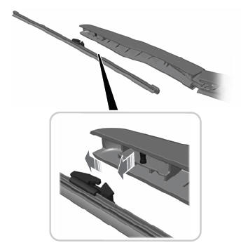
    Note: Do not hold the wiper blade to lift the wiper arm.

    Remove the wiper blade.

    read more

    Copyright © 2024 www.linautilus.com