Lincoln Nautilus: Driveshaft / Driveshaft Angle Measurement. General Procedures
Check
NOTE: This procedure does not apply to CV joints, flex couplers or double cardan joints that are used in some driveshafts. This check is for single-cross and roller-style joints found in the driveshafts.
NOTE: Prior to checking driveline angularity, inspect the U-joints for correct operation.
NOTE: An incorrect driveline angle can cause a vibration or shudder.
NOTE: Driveline angularity is the angular relationship between the engine crankshaft, the driveshaft and the rear axle pinion. Factors determining driveline angularity include ride height, rear spring and engine mounts.
-
NOTE:
- Special Tool(s): Anglemaster II Driveline Inclinometer/Protractor 164-R2402. Carry out the following preliminary setup steps:
-
Inspect the U-joints for correct operation.
-
Park the vehicle on a level surface such as a drive-on hoist or back onto a front end alignment rack.
-
Verify the curb position ride height is within
specifications with the vehicle unloaded and all of the tires are
inflated to their normal operating pressures.
-
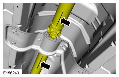
Calibrate the Anglemaster II Driveline
Inclinometer/Protractor by placing it on a clean, flat level section of
the frame rail and press the ALT-ZERO button.
Vehicles with flat-flanged, split-pin or slip-flanged U-joints
-
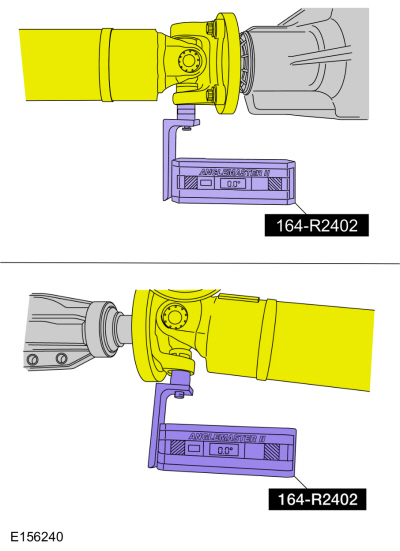
NOTE: If equipped, remove the snap ring to allow access to the base of the U-joint cup. Make sure the Anglemaster II Driveline Inclinometer/Protractor is seated against the U-joint cup.
NOTE: Rotate the driveshaft until the flange U-joint cup is parallel with the floor. This will simplify taking measurements.
Special Tool(s): Anglemaster II Driveline Inclinometer/Protractor 164-R2402. Check and record the flange angle as angle "A".
 |
-
Special Tool(s): Anglemaster II Driveline
Inclinometer/Protractor 164-R2402. Measure the slope of the connecting
component. Record the measurement of the component angle as angle "B".
 |
Multiple piece driveshafts
-
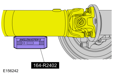
NOTE: Repeat this step for each center support bearing on the driveshaft.
NOTE: It is not necessary to remove the U-joint snap ring, if equipped, for these measurements.
Special Tool(s): Anglemaster II Driveline Inclinometer/Protractor 164-R2402. Measure the slope of the components in front and behind the center support bearing U-joint in the area indicated. Record the front component as angle A and the rear component as angle "B".
 |
All vehicles
-
NOTE: When 2 connected components slope in the same direction, subtract the smallest number from the larger number to find the U-joint operating angle. When 2 connected components slope in the opposite direction, add the measurements to find the U-joint operating angle.
Calculate the difference in the slope of the components to determine the U-joint operating angle.
-
NOTE:
- The U-joint operating angle is the angle formed by 2 yokes connected by a cross and bearing kit. Ideally, the operating angles on each connection of the driveshaft must:
-
be equal or within one degree of each other.
-
have a 3 degree maximum operating angle.
-
have at least one-half of one degree continuous operating angle.
-
If the angle is not within specifications, repair or
adjust to obtain the correct angle. Inspect the engine mounts,
transmission mounts, center support bearing mounting, rear suspension,
rear axle, rear axle mounting or the frame for wear or damage.
 Driveshaft. Diagnosis and Testing
Preliminary Inspection
Verify the customer concern.
Visually inspect the CV joints for obvious signs of mechanical damage.
If an obvious cause for an observed or reported concern is
found, correct the cause (if possible) before proceeding to the next
step
If the cause is not visually evident, verify the symptom and REFER to Symptom Chart: NVH...
 Driveshaft Runout and Balancing. General Procedures
Special Tool(s) /
General Equipment
100-002
(TOOL-4201-C)
Holding Fixture with Dial Indicator Gauge
Inspection
NOTE:
Driveline vibration exhibits a higher frequency and lower
amplitude then high-speed shake...
Other information:
Lincoln Nautilus 2018-2026 Owners Manual: Accessories
For a complete listing of the accessories that are available for your vehicle, please contact your authorized dealer or visit the online store website: Web Address (United States) www.Accessories.Lincoln.com Web Address (Canada) www.LincolnCanada.com We will repair or replace any properly authorized dealer-installed Lincoln Original Accessory found to be defective in factory-supplied materia..
Lincoln Nautilus 2018-2026 Owners Manual: Towing a Trailer Precautions. Trailer Brake Precautions. Towing a Trailer Limitations
Towing a Trailer Precautions WARNING: Do not exceed the GVWR or the GAWR specified on the certification label. WARNING: Towing trailers beyond the maximum recommended gross trailer weight exceeds the limit of your vehicle and could result in engine damage, transmission damage, structural damage, loss of vehicle control, vehicle rollover and personal injury. WARNING: Do not exceed the low..
Categories
- Manuals Home
- 1st Generation Nautilus Owners Manual
- 1st Generation Nautilus Service Manual
- Engine Oil Capacity and Specification - 2.0L
- USB Ports
- Opening the Liftgate
- New on site
- Most important about car
Auto-Start-Stop
What Is Auto-Start-Stop
The system is designed to help reduce fuel consumption and CO2 emissions by stopping the engine when it is idling, for example at traffic lights.
Auto-Start-Stop Precautions
WARNING: Apply the parking brake, shift into park (P), switch the ignition off and remove the key before you leave your vehicle. Failure to follow this instruction could result in personal injury or death.
WARNING: Apply the parking brake, shift into park (P), switch the ignition off and remove the key before you open the hood or have any service or repair work completed. If you do not switch the ignition off, the engine could restart at any time. Failure to follow this instruction could result in personal injury or d