Lincoln Nautilus: Body Closures / Rear Door Alignment. General Procedures
Inspection
NOTE:
Removal steps in this procedure may contain installation details.
NOTE:
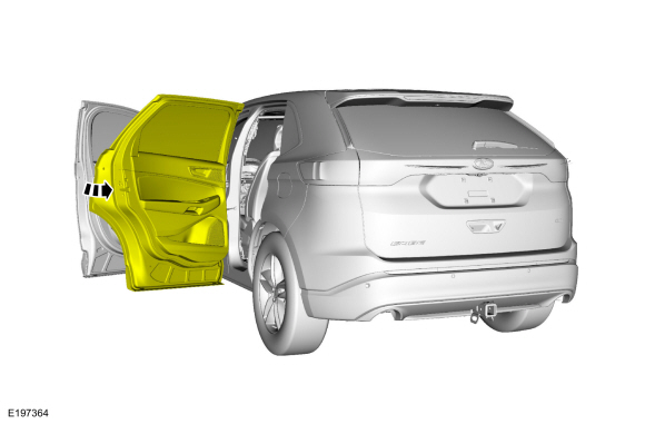
LH side shown, RH side similar.
-
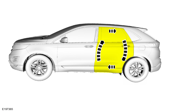
Inspect the rear door-to-body dimensions.
Refer to: Body and Frame (501-26 Body Repairs - Vehicle Specific Information and Tolerance Checks, Description and Operation).
Adjustment
All alignments
-
Open the rear door.
-
Remove the bolts and the striker assembly.
Torque:
18 lb.ft (25 Nm)
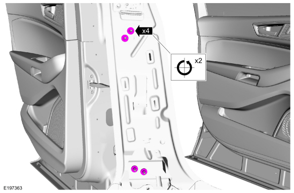
Rear door in and out, up and down alignment
-
Loosen the bolts to permit movement of the door.
Loosen:
:
2 turn(s)
-
Adjust the door to specification.
Refer to: Body and Frame (501-26 Body Repairs - Vehicle Specific Information and Tolerance Checks, Description and Operation).
-
Tighten the bolts.
Torque:
35 lb.ft (48 Nm)
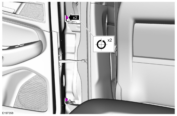
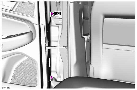
Rear door fore, aft and tilt alignment
-
Remove the lower B-pillar trim panel.
Refer to: B-Pillar Trim Panel (501-05 Interior Trim and Ornamentation, Removal and Installation).
-
Depower the SRS .
Refer to: Supplemental Restraint System (SRS) Depowering (501-20 Supplemental Restraint System)
.
-
Remove the bolt and position aside the safety belt retractor.
-
Open the front door.
-
Loosen the nuts to permit movement of the door.
Loosen:
:
2 turn(s)
-
Carefully close the rear door.
-
Carefully close the front door.
-
Adjust the door to specification.
Refer to: Body and Frame (501-26 Body Repairs - Vehicle Specific Information and Tolerance Checks, Description and Operation).
-
Carefully open the front door.
-
Carefully open the rear door.
-
Tighten the nuts.
Torque:
22 lb.ft (30 Nm)
-
Install the safety belt retractor and the bolt.
Torque:
30 lb.ft (40 Nm)
-
NOTE:
During installation, make sure the safety belt
webbing is not twisted and the safety belts and buckles are accessible
to the occupants.
Repower the SRS .
Refer to: Supplemental Restraint System (SRS) Repowering (501-20 Supplemental Restraint System)
.
-
Check the active restraint system for correct operation.
Refer to: Seatbelt Systems (501-20 Seatbelt Systems)
.
All alignments
-
Install the striker assembly.
Torque:
18 lb.ft (25 Nm)
-
Inspect the body-to-rear door dimensions.
Refer to: Body and Frame (501-26 Body Repairs - Vehicle Specific Information and Tolerance Checks, Description and Operation).
Initialization
Disconnect the battery or remove the RGTM fuse(s).
Refer to: Battery Disconnect and Connect (414-01 Battery, Mounting and Cables, General Procedures)...
Special Tool(s) /
General Equipment
Door Lift
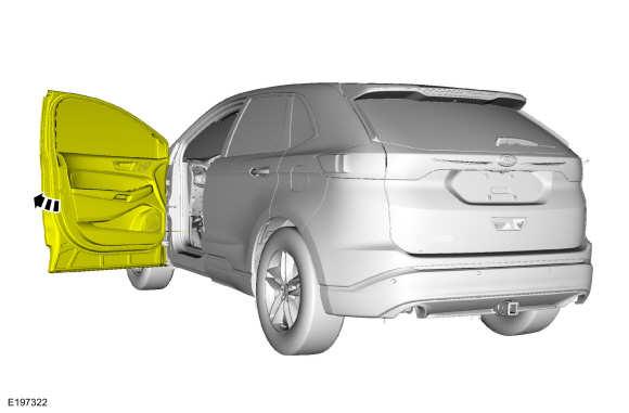
Removal
NOTE:
Removal steps in this procedure may contain installation details.
NOTE:
LH side shown, RH side similar...
Other information:
DTC Chart: SCCM
Diagnostics in this manual assume a certain skill level and knowledge of Ford-specific diagnostic practices. REFER to: Diagnostic Methods (100-00 General Information, Description and Operation).
SCCM
DTC Chart
DTC
Description
Action
B1298:09
Steering Column Adjust Up Switch: Component Failure
NOTE:
..
DTC Chart(s)
Diagnostics in this manual assume a certain skill level and knowledge of Ford-specific diagnostic practices. REFER to: Diagnostic Methods (100-00 General Information, Description and Operation).
SODL and SODR
DTC Chart
DTC
Description
Action
B11D6:11
Driver Display Alert LED: Circuit Short To Ground
..
.jpg)
.jpg)
.jpg)
.jpg)
.jpg)

.jpg)

.jpg)
 Power Liftgate Initialization. General Procedures
 Front Door. Removal and Installation