Lincoln Nautilus: Bumpers / Front Bumper. Removal and Installation
Lincoln Nautilus 2018-2026 Service Manual / Body and Paint / Body and Paint / Bumpers / Front Bumper. Removal and Installation
Removal
NOTE: Removal steps in this procedure may contain installation details.
All vehicles
-
Remove the front bumper cover.
Refer to: Front Bumper Cover (501-19 Bumpers, Removal and Installation).
-
Remove the headlamp assembly.
Refer to: Headlamp Assembly (417-01 Exterior Lighting, Removal and Installation).
-
Remove the CCM .
Refer to: Cruise Control Module (CCM) (419-03B Cruise Control - Vehicles With: Adaptive Cruise Control With Lane Centering, Removal and Installation).
-
Remove the horn.
Refer to: Horn (413-06 Horn, Removal and Installation).
-
Remove the ambient air temperature sensor.
-
Disconnect the ambient air temperature sensor electrical connector.
-
Separate the ambient air temperature sensor from the grille opening panel.
-
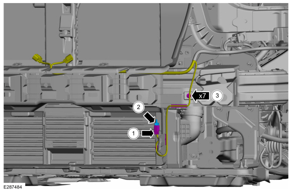
Separate the front bumper wiring harness guides and position the front bumper wiring harness aside.
-
Disconnect the ambient air temperature sensor electrical connector.
 |
-
Release the tabs and remove the front bumper energy absorber.
.jpg) |
Vehicles equipped with active grille shutter
-
Remove the active grille shutter assembly.
Refer to: Active Grille Shutter (501-02 Front End Body Panels, Removal and Installation).
Vehicles not equipped with active grille shutters
-
Remove the grille opening panel bolts.
Torque:
1.: 35 lb.in (4 Nm)
2.: 71 lb.in (8 Nm)
.jpg) |
-
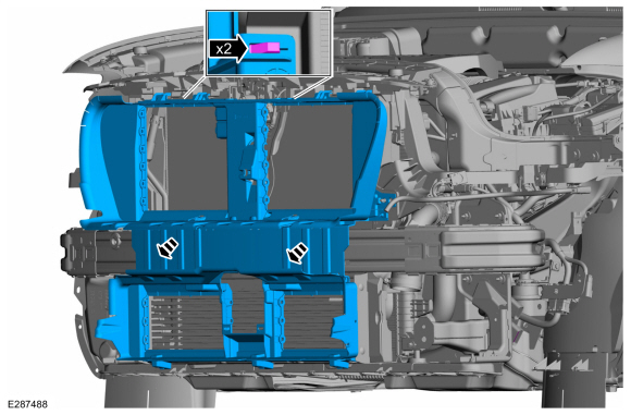
Release the clips and remove the grille opening panel.
 |
-
Remove the lower washer reservoir screw.
Torque: 28 lb.in (3.2 Nm)
.jpg) |
-
Support the lower radiator support.
-
Remove the bolts from the lower radiator support.
Torque: 18 lb.ft (24 Nm)
.jpg) |
-
Lower the lower radiator support for clearance to the front bumper.
-
Remove the front bumper nuts.
Torque: 18 lb.ft (24 Nm)
.jpg) |
-
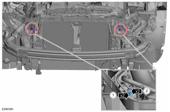
Remove the front bumper adjuster assemblies.
-
Remove the front bumper adjuster bolts.
Torque: 177 lb.in (20 Nm)
-
Remove the front bumper adjusters.
-
Remove the front bumper adjuster bolts.
 |
-
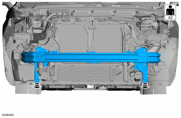
With the help of an assistant.
Remove the front bumper.
 |
Installation
-
To install, reverse the removal procedure.
 Bumpers
..
 Front Bumper Cover. Removal and Installation
Removal
NOTE:
Removal steps in this procedure may contain installation details.
Remove the front wheel and tire assemblies.
Refer to: Wheel and Tire (204-04A Wheels and Tires, Removal and Installation)...
Other information:
Lincoln Nautilus 2018-2026 Service Manual: Seatbelt Systems. Diagnosis and Testing
Symptom Chart(s) Diagnostics in this manual assume a certain skill level and knowledge of Ford-specific diagnostic practices. REFER to: Diagnostic Methods (100-00 General Information, Description and Operation). Preliminary Inspection Before diagnosing or repairing the seatbelt system, inspect the following items: Seatbelt webbing integrity (torn, frayed, cut or stretched) Seat..
Lincoln Nautilus 2018-2026 Owners Manual: Launching or Retrieving a Boat or Personal Watercraft. Towing Weights and Dimensions
Launching or Retrieving a Boat or Personal Watercraft When backing down a ramp during boat launching or retrieval: Do not allow the static water level to rise above the bottom edge of the rear bumper. Do not allow waves to break higher than 6 in (15 cm) above the bottom edge of the rear bumper. Exceeding 6 in (15 cm) could allow water to enter vehicle components, causing internal da..
Categories
- Manuals Home
- 1st Generation Nautilus Owners Manual
- 1st Generation Nautilus Service Manual
- Replacing the Rear Wiper Blades
- Opening and Closing the Hood
- Anti-Theft Alarm System Settings. Security – Troubleshooting
- New on site
- Most important about car
Parking Aid Indicators. Parking Aids – Troubleshooting
Parking Aid Indicators
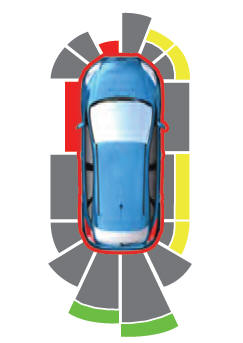
The system provides object distance indication through the information and entertainment display.
As the distance to the object decreases, the indicator waves and the lines move toward the vehicle icon. If there is no object detected, the distance indicator lines are grey.Copyright © 2026 www.linautilus.com