Lincoln Nautilus: Vehicle Dynamic Suspension / Vehicle Dynamic Suspension - System Operation and Component Description. Description and Operation
System Operation
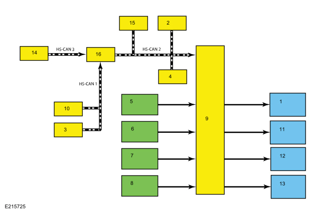
System Diagram

| Item | Description |
|---|---|
| 1 | LH front valve solenoid |
| 2 | PSCM |
| 3 | PCM |
| 4 | ABS module |
| 5 | LH front height sensor |
| 6 | RH front height sensor |
| 7 | LH rear height sensor |
| 8 | RH rear height sensor |
| 9 | VDM |
| 10 | BCM |
| 11 | RH front valve solenoid |
| 12 | LH rear valve solenoid |
| 13 | RH rear valve solenoid |
| 14 | IPC |
| 15 | RCM |
| 16 | GWM |
Network Message Chart
Module Network Input Messages - VDM
| Broadcast Message | Originating Module | Message Purpose |
|---|---|---|
| ABS active | ABS module | Indicates the current ABS activity, on or off. |
| Accelerator pedal position | PCM | This message is sent to the GWM and then to the VDM . Indicates the current accelerator pedal position in percentage of travel with 0% at rest and 100% at full throttle. |
| Ambient air temperature | PCM | This message is sent to the GWM and then to the VDM . Indicates the current ambient air temperature in degrees Celsius. |
| Brake torque request | ABS module | This message indicates the total amount of braking, in newton meters, requested by the driver (via the brake pedal), the adaptive cruise control system or the collision avoidance system. The VDM adjusts the valve solenoids to help stabilize the vehicle during the operation of those systems. |
| Driven wheel torque | PCM | This message is sent to the GWM and then to the VDM . Indicates the current amount of torque, in Newton meters, available to the driven wheels. |
| Engine RPM data | PCM | This message is sent to the GWM and then to the VDM . Indicates the current engine RPM . |
| Fuel level | IPC | This message is sent to the GWM and then to the VDM . Indicates the current fuel level as a percentage. The VDM uses fuel level when calculating suspension settings and uses a default setting when the information is not available.. |
| Gear lever position | PCM | This message is sent to the GWM and then to the VDM . Indicates the current transmission gear status. Used to determine the amount of dampening required during vehicle operation. |
| Ignition status | BCM | This message is sent to the GWM and then to the VDM . Indicates the current ignition status; off, accessory, run, start, invalid or unknown. |
| Life cycle mode | BCM | This message is sent to the GWM and then to the VDM . Indicates the current vehicle life cycle; normal, factory, not used or transport. |
| Message center feature configuration | IPC | This message indicates the current driver selected vehicle suspension mode: normal, comfort or sport. |
| Odometer master value | IPC | This message is sent to the GWM and then to the VDM . Indicates the current odometer value in kilometers and whether the data is fresh or unchanged. |
| Power pack status | PCM | This message is sent to the GWM and then to the VDM . Indicates the current status of the engine and powertrain; Off - torque not available, On - torque not available, start in progress - torque not available or On - torque available. |
| Stability control event in progress | ABS module | Indicates a stability control system (traction control or ESC ) is currently active. |
| Stability control indicator request | ABS module | Indicates the current stability control warning indicator status; on, off, slow flash or fast flash. |
| Stability control mode | ABS module | Indicates the current ESC activity, on or off. Also indicates if one or more of the stability control systems is faulted. |
| Steering angle data | PSCM | Indicates the current steering wheel angle relative to the straight ahead position. |
| Traction control mode | ABS module | Indicates the current traction control activity, active or inactive. Also indicates if the traction control system is faulted. |
| Vehicle configuration data | BCM | This message is sent to the GWM and then to the VDM . Indicates the current vehicle configuration and optional equipment. |
| Vehicle lateral acceleration | ABS module | Indicates the current lateral acceleration of the vehicle in meters per second squared as measured by the sensors in the RCM and relayed by the ABS module. |
| Vehicle lateral acceleration | RCM | Indicates the current lateral acceleration of the vehicle in meters per second squared as measured by the sensors in the RCM . |
| Vehicle longitudinal acceleration | ABS module | Indicates the current longitudinal acceleration of the vehicle in meters per second squared as measured by the sensors in the RCM and relayed by the ABS module. |
| Vehicle longitudinal acceleration | RCM | Indicates the current longitudinal acceleration of the vehicle in meters per second squared as measured by the sensors in the RCM . |
| Vehicle roll rate | ABS module | Indicates the current roll rate of the vehicle in radians per second squared as measured by the sensors in the RCM and relayed by the ABS module. |
| Vehicle roll rate | RCM | Indicates the current roll rate of the vehicle in radians per second squared as measured by the sensors in the RCM . |
| Vehicle speed | PCM | This message is sent to the GWM and then to the VDM . Indicates the current vehicle speed in kilometers per hour. |
| Vehicle stability index | ABS module | Indicates the current stability (oversteer or understeer) of the vehicle. |
| Vehicle vertical acceleration | ABS module | Indicates the current vertical acceleration of the vehicle in meters per second squared as measured by the sensors in the RCM and relayed by the ABS module. |
| Vehicle vertical acceleration | RCM | Indicates the current vertical acceleration of the vehicle in meters per second squared as measured by the sensors in the RCM and relayed by the ABS module. |
Vehicle Dynamic Suspension
The VDM is connected to the HS-CAN2 to communicate with other modules. The VDM also gathers suspension height information from 4 height sensors. With the information received, the VDM monitors the heave, roll, pitch, cornering, braking and acceleration of the vehicle. Based on this information the VDM calculates the best action for each valve solenoid.
Once the valve solenoid is energized, the damping increases with the PWM duty cycle. At minimum current the damping is less than when max current is applied. The damper and valve solenoid have been designed so failure leads to a firm ride. The fail-safe level of damping is at a level equivalent to what is produced at higher currents, but it is not the same as the maximum current.
The driver can select 1 of 3 preset system modes (Comfort, Normal or Sport) using the message center. When a mode is selected, the VDM regulates the PWM signal to the valve solenoids to keep the suspension "feel" relational to the selected mode.
When the VDM is initialized (ignition ON), the module carries out a preliminary electrical check of the height sensors, height sensor circuits, valve solenoids and valve solenoid circuits. Any malfunction detected in the system causes the VDM to set a DTC and send a message over the HS-CAN to the IPC . The IPC responds by displaying a message in the message center. Depending on the DTC present, the VDM may deactivate the dynamic suspension system resulting in a firm suspension feel.
Component Description
Vehicle Dynamics Control Module (VDM)
The VDM is the ECU for the vehicle dynamic suspension. The VDM monitors all sensor inputs and all HS-CAN2 messages relating to the vehicle dynamic suspension and then directly controls the valve solenoids.
When a new VDM is installed, the module must be programmed with the vehicle configuration information.
Refer to: Module Configuration (418-01 Module Configuration)
.
When one of the following components is installed new, disassembled, disconnected or removed the VDM requires calibration.
- VDM
- Suspension height sensor
- Front lower control arm
- Front strut assembly
- Rear lower control arm
- Rear shock
The calibration procedure is required for the system to learn the zero-position of the vehicle which means the vehicle must be on a level surface, must not be moving and cannot contain any passengers or cargo. The calibration procedure is carried out using a diagnostic scan tool. The calibration routine should not be performed with the vehicle raised off the ground or immediately after lowering the vehicle as the suspension will not be in a neutral position. The suspension must be neutralized before performing the calibration routine by driving the vehicle for a short distance such as around a parking lot.
Height Sensor
The height sensor uses a potentiometer to send a variable amount of voltage back to the VDM based on suspension height. The sensor has 3 circuits, one circuit is for the 5 volt sensor supply, one circuit is for sensor ground and one circuit is for the sensor output.
Valve Solenoid
The VDM uses a PWM output to control the valve solenoid. The solenoid opens or closes the valve depending on the amount of current supplied by the VDM . The higher the current, the more the valve is opened, resulting in a higher level of damping.
 Vehicle Dynamic Suspension - Overview. Description and Operation
Overview
The
semi-active suspension dampening provides improved handling, comfort
and stability by continuously adjusting the adaptive shock absorber
force to the current road and driving conditions...
 Vehicle Dynamic Suspension. Diagnosis and Testing
DTC Chart
VDM
DTC Chart
Diagnostics in this manual assume a certain skill level and knowledge of Ford-specific diagnostic practices. REFER to: Diagnostic Methods (100-00 General Information, Description and Operation)...
Other information:
Lincoln Nautilus 2018-2026 Service Manual: Brake Fluid Reservoir. Removal and Installation
Materials Name Specification Motorcraft® DOT 4 LV High Performance Motor Vehicle Brake FluidPM-20 WSS-M6C65-A2 Removal NOTICE: Do not spill brake fluid on painted or plastic surfaces or damage to the surface may occur...
Lincoln Nautilus 2018-2026 Owners Manual: Mislock
What Is Mislock Mislock is a locking feature that warns you if your vehicle has not locked. Mislock Limitations When you press the lock button once, the direction indicators do not flash if: Any door or the liftgate is open. The hood is open. If you switch mislock off, the horn does not sound if you press the lock button on the remote control when a door is open...
Categories
- Manuals Home
- 1st Generation Nautilus Owners Manual
- 1st Generation Nautilus Service Manual
- Interior Lamp Function. Adjusting the Instrument Panel Lighting Brightness. Ambient Lighting. Interior Lighting – Troubleshooting
- Auto-Start-Stop
- Auto Hold
- New on site
- Most important about car
Changing a Flat Tire
WARNING: If the tire pressure monitor sensor becomes damaged it may not function.
Note: The use of tire sealant may damage your tire pressure monitoring system and should only be used in roadside emergencies. If you must use a sealant, use the Tire Mobility Kit sealant. Replace the tire pressure monitoring system sensor and valve stem on the wheel by an authorized dealer after use of the sealant.
Note: The tire pressure monitoring system indicator light will illuminate when the spare tire is in use. To restore the full function of the monitoring system, all road wheels equipped with tire pressure monitoring sensors must be mounted on the vehicle.
If you get a flat tire while driving, do not apply the brake hea