Lincoln Nautilus: Suspension System - General Information / Front Camber Adjustment. General Procedures
Special Tool(s) / General Equipment
| Wheel Alignment System |
Adjustment
NOTICE: Suspension fasteners are critical parts that affect the performance of vital components and systems. Failure of these fasteners may result in major service expense. Use the same or equivalent parts if replacement is necessary. Do not use a replacement part of lesser quality or substitute design. Tighten fasteners as specified.
-
Using alignment equipment and the manufacturer's instructions, measure the front camber.
Use the General Equipment: Wheel Alignment System
-
Remove the wheel and tire.
Refer to: Wheel and Tire (204-04A Wheels and Tires, Removal and Installation).
-
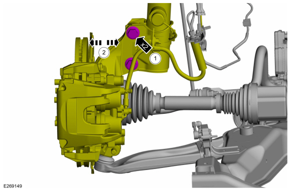
NOTE: Support the wheel spindle using mechanic's wire.
Remove and discard the strut-to-wheel knuckle bolts and nuts.
 |
-
-
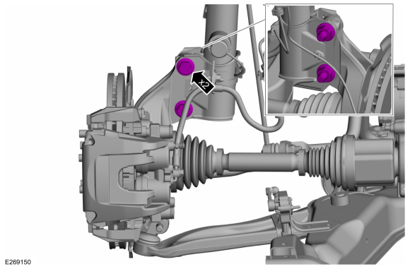
NOTE: Replace bolts and nuts with new service bolts and nuts.
NOTE: Original equipment bolts are splined, service bolts are smooth and smaller in diameter.
NOTE: Do not fully tighten the strut-to-spindle bolts and nuts until the alignment has been corrected.
Install the 2 new service strut-to-wheel knuckle bolts and nuts and tighten until snug.
-
NOTE: Adjustment from maximum inboard to maximum outboard is .5 °.
Move the wheel knuckle assembly inboard or outboard to adjust front camber as necessary.
-
 |
-
Tighten the strut-to-wheel knuckle bolts and nuts.
Torque: 173 lb.ft (235 Nm)
 |
-
Install the wheel and tire.
Refer to: Wheel and Tire (204-04A Wheels and Tires, Removal and Installation).
-
Recheck alignment to verify camber change and adjust front toe if necessary.
Refer to: Front Toe Adjustment (204-00 Suspension System - General Information, General Procedures).
 Suspension System. Diagnosis and Testing
Preliminary Inspection
Road test the vehicle.
If any suspension alignment or ride height concerns are present, REFER to Symptom Chart: Suspension System...
 Front Toe Adjustment. General Procedures
Special Tool(s) /
General Equipment
Wheel Alignment System
Adjustment
NOTE:
Make sure that the vehicle is standing on a level surface.
Steering wheel in straight ahead position...
Other information:
Lincoln Nautilus 2018-2026 Service Manual: Low Voltage Differential Signalling (LVDS) Cable. Removal and Installation
Removal Remove the information and entertainment display unit. Remove the GSM . Refer to: Gear Shift Module (GSM) (307-05A Automatic Transmission External Controls - 8-Speed Automatic Transmission – 8F57, Removal and Installation)...
Lincoln Nautilus 2018-2026 Service Manual: Wheel and Tire Health and Safety Precautions. Description and Operation
WARNING: Never inflate a tire that has been run flat without first removing the tire from the wheel to inspect for damage. A damaged tire can fail during inflation. Failure to follow this instruction may result in serious personal injury...
Categories
- Manuals Home
- 1st Generation Nautilus Owners Manual
- 1st Generation Nautilus Service Manual
- Child Safety Locks
- Replacing the Rear Wiper Blades
- Auto Hold
- New on site
- Most important about car
Replacing the Rear Wiper Blades
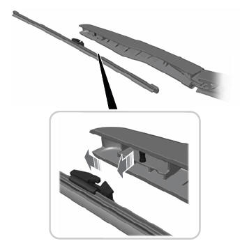
Note: Do not hold the wiper blade to lift the wiper arm.
Remove the wiper blade.