Lincoln Nautilus: Front End Sheet Metal Repairs / Front Side Member Section. Removal and Installation
Special Tool(s) /
General Equipment
| Resistance Spotwelding Equipment |
| Spherical Cutter |
| Air Body Saw |
| 8 mm Drill Bit |
| MIG/MAG Welding Equipment |
| Spot Weld Drill Bit |
| Locking Pliers |
Materials
| Name |
Specification |
Seam Sealer
TA-2-B, 3M™ 08308, LORD Fusor® 803DTM |
-
|
Removal
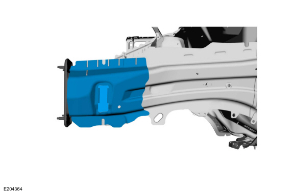
NOTE:
This procedure is intended for sectioning a small portion of the front side member when collision damage is minimal.
LH side shown, RH side similar.
-
Restore the vehicle to pre-accident dimensions, if required.
Refer to: Body and Frame (501-26 Body Repairs - Vehicle Specific Information and Tolerance Checks, Description and Operation).
-
Remove the following items:
-
Remove the bumper.
Refer to: Front Bumper (501-19 Bumpers, Removal and Installation).
-
Remove the headlamp assembly.
Refer to: Headlamp Assembly (417-01 Exterior Lighting, Removal and Installation).
-
Remove the fender.
Refer to: Fender (501-02 Front End Body Panels, Removal and Installation).
-
Remove the fender splash shield.
Refer to: Fender Splash Shield (501-02 Front End Body Panels, Removal and Installation).
-
Remove the cooling module (as equipped).
Refer to: Cooling Module (303-03B Engine Cooling - 2.7L EcoBoost (238kW/324PS), Removal and Installation).
-
Remove the hood.
Refer to: Hood (501-02 Front End Body Panels, Removal and Installation).
-
Remove the subframe.
Refer to: Front Subframe (502-00 Uni-Body, Subframe and Mounting System, Removal and Installation).
-
Remove the battery, LH side only.
Refer to: Battery (414-01 Battery, Mounting and Cables, Removal and Installation).
-
Remove the radiator grille opening panel.
-
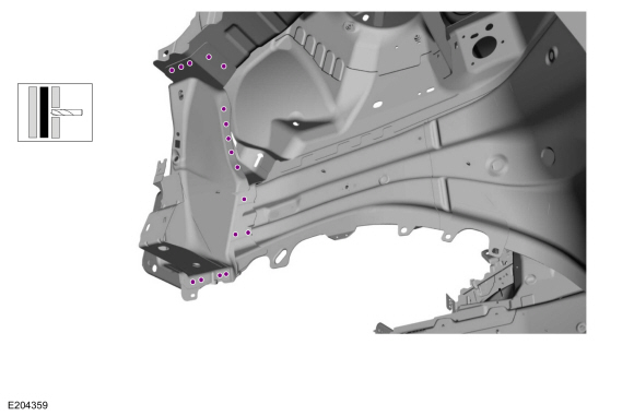
Remove the spot welds on the fender mounting bracket.
Use the General Equipment: Spot Weld Drill Bit
-
Remove the spot welds on the fender mounting bracket front flange.
Use the General Equipment: Spot Weld Drill Bit
-
Remove the fender mounting bracket.
-
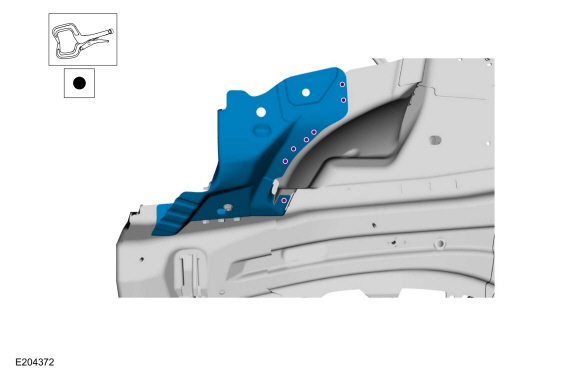
Remove the spot welds and remove the panel from the fender apron assembly.
Use the General Equipment: Spot Weld Drill Bit
-
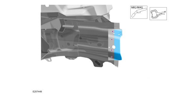
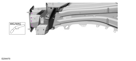
Remove the spot welds on the outer side member.
Use the General Equipment: Spot Weld Drill Bit
-
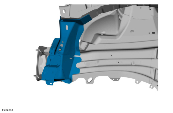
Remove the section on the outer side member.
-
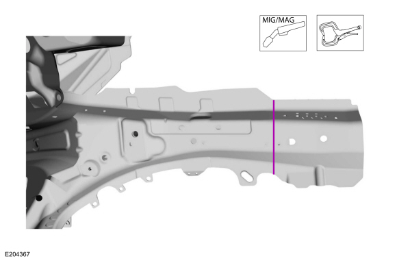
NOTICE:
Cut through the inner side member only.
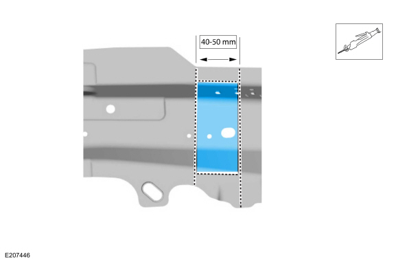
Measure and cut the inner side member and remove.
Use the General Equipment: Spherical Cutter
Use the General Equipment: Air Body Saw
Installation
-
Measure and cut section from the replacement part.
Use the General Equipment: Spherical Cutter
Use the General Equipment: Air Body Saw
-
Create a backer piece from a suitable piece of the inner frame rail material.
-
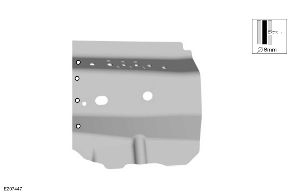
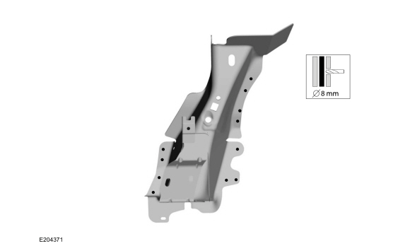
Drill holes for plug welding the replacement inner frame rail section.
Use the General Equipment: 8 mm Drill Bit
-
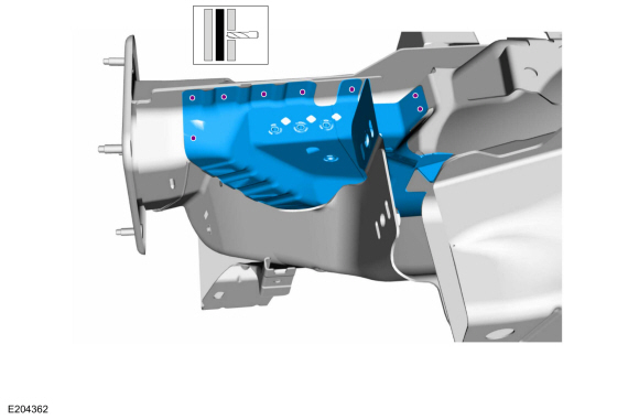
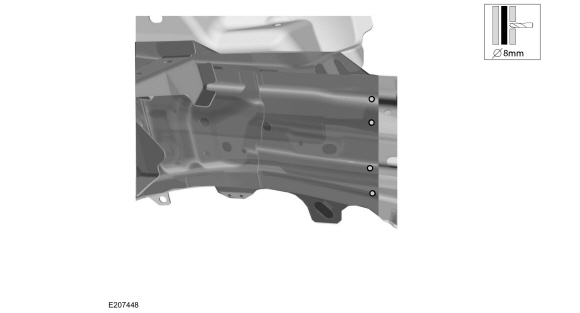
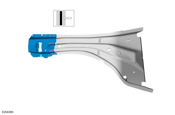
NOTE:
Fender apron panel and engine mounting brackets removed from view for clarity.
Drill holes for plug welding in the inner frame rail section.
Use the General Equipment: 8 mm Drill Bit
-
Install the backer reinforcement and weld to the inner frame rail.
Use the General Equipment: Locking Pliers
Use the General Equipment: MIG/MAG Welding Equipment
-
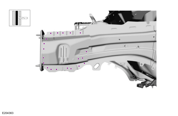
NOTE:
Check for dimensional accuracy before welding.
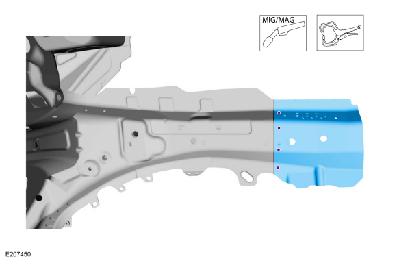
Install the frame rail replacement section and weld.
-
Seam weld the replacement section.
Use the General Equipment: MIG/MAG Welding Equipment
Use the General Equipment: Locking Pliers
-
NOTE:
Original panel may be reused if undamaged, otherwise
replacement panel will need to be removed from a new fender apron
assembly and installed.
Remove the panel from the fender apron assembly.
Use the General Equipment: Spot Weld Drill Bit
-
Remove section from the replacement part.
Use the General Equipment: Spot Weld Drill Bit
-
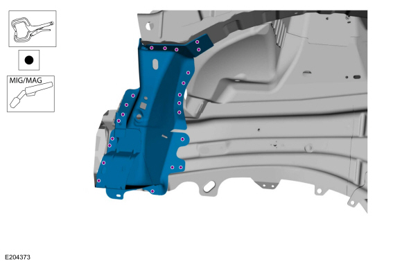
Install the replacement section and weld.
Use the General Equipment: MIG/MAG Welding Equipment
Use the General Equipment: Resistance Spotwelding Equipment
Use the General Equipment: Locking Pliers
-
Install the panel to the fender apron assembly and resistance spot weld.
Use the General Equipment: Locking Pliers
Use the General Equipment: Resistance Spotwelding Equipment
-
Drill holes in the replacement fender mounting bracket for plug welding.
Use the General Equipment: 8 mm Drill Bit
-
Install the fender mounting bracket and weld.
Use the General Equipment: MIG/MAG Welding Equipment
Use the General Equipment: Resistance Spotwelding Equipment
Use the General Equipment: Locking Pliers
-
Weld the panel flanges.
Use the General Equipment: MIG/MAG Welding Equipment
Use the General Equipment: Resistance Spotwelding Equipment
-
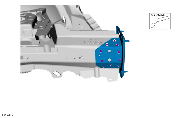
Drill holes in the bumper mount bracket replacement part for plug welding.
Use the General Equipment: 8 mm Drill Bit
-
Install the bumper mounting bracket and weld to the inner side member.
Use the General Equipment: MIG/MAG Welding Equipment
-
Complete welding the bumper mounting bracket on the outer side member.
Use the General Equipment: MIG/MAG Welding Equipment
-
Complete all panel sectioning seams using typical metal finishing techniques.
-
Prime the entire repair using a Ford approved paint system.
-
Sealing work: All areas must be sealed to production level.
Material: Seam Sealer
/ TA-2-B, 3M™ 08308, LORD Fusor® 803DTM
-
Refinish using a Ford approved paint system.
-
Restore corrosion protection.
Refer to: Corrosion Prevention (501-25 Body Repairs - General Information, General Procedures).
-
Install the radiator grille opening panel.
-
Install the following items:
-
Install the subframe.
Refer to: Front Subframe (502-00 Uni-Body, Subframe and Mounting System, Removal and Installation).
-
Install the cooling module (as equipped).
Refer to: Cooling Module (303-03B Engine Cooling - 2.7L EcoBoost (238kW/324PS), Removal and Installation).
-
Install the battery, LH side only.
Refer to: Battery (414-01 Battery, Mounting and Cables, Removal and Installation).
-
Remove the fender splash shield.
Refer to: Fender Splash Shield (501-02 Front End Body Panels, Removal and Installation).
-
Install the fender.
Refer to: Fender (501-02 Front End Body Panels, Removal and Installation).
-
Install the headlamp assembly.
Refer to: Headlamp Assembly (417-01 Exterior Lighting, Removal and Installation).
-
Install the bumper.
Refer to: Front Bumper (501-19 Bumpers, Removal and Installation).
Special Tool(s) /
General Equipment
Air Body Saw
8 mm Drill Bit
MIG/MAG Welding Equipment
Spot Weld Drill Bit
Locking Pliers
Materials
Name
Specification
Seam SealerTA-2-B, 3M™ 08308, LORD Fusor® 803DTM
-
Removal
NOTE:
Left hand (LH) side shown, right hand (RH) side similar...
Other information:
Switching the Audio Unit On and Off
Press the button on the volume
control.
Selecting the Audio Source
Audio Unit
Press the button to open the
media
source menu.
You can press this multiple times to change
to the audio source or scroll through the
media sources.
Touchscreen
Press Sources on the touchscreen to open
the media source menu.
Playing or Pausing the Audio Source
Touchscreen
Pres..
Preliminary Inspection
Visually inspect the CV joints, housing, boots, and clamps for obvious signs of mechanical damage.
If an obvious cause for an observed or reported concern is
found, correct the cause (if possible) before proceeding to the next
step
If the cause is not visually evident, verify the symptom and REFER to Symptom Chart: NVH.
Symptom Chart(s)
Diagn..
Categories
How Does Traction Control Work
If your vehicle begins to slide, the system
applies the brakes to individual wheels and,
when needed, reduces power at the same
time. If the wheels spin when accelerating
on slippery or loose surfaces, the system
reduces power in order to increase traction.
Switching Traction Control On and Off
WARNING: The stability and traction
control light illuminates steadily if the
system detects a failure. Make sure you
did not manually disable the traction
control system using the information
display controls or the switch. If the stability
control and traction control light is still
illuminating steadily, have the system
serviced by an authorized dealer
immediately. Operating your vehicle with
the traction co
read more
.jpg)
.jpg)
.jpg)
.jpg)
.jpg)
.jpg)
.jpg)
 Front Side Member and Fender Apron Panel LH. Removal and Installation