Lincoln Nautilus: Front End Sheet Metal Repairs / Front Side Member and Fender Apron Panel LH. Removal and Installation
Special Tool(s) /
General Equipment
| Air Body Saw |
| 8 mm Drill Bit |
| MIG/MAG Welding Equipment |
| Spot Weld Drill Bit |
| Locking Pliers |
Materials
| Name |
Specification |
Seam Sealer
TA-2-B, 3M™ 08308, LORD Fusor® 803DTM |
-
|
Removal
NOTE:
Left hand (LH) side shown, right hand (RH) side similar.
NOTE:
Factory welds may be substituted with resistance or metal
inert gas (MIG) plug welds. Resistance welds may not be placed directly
over original location. They must be placed adjacent to original
location and match factory welds in quantity. Metal inert gas (MIG) plug
welds must equal factory welds in both location and quantity.
NOTE:
Adequately protect all adjacent areas against cutting, grinding and welding procedures.
-
Depower the SRS .
Refer to: Supplemental Restraint System (SRS) Depowering (501-20B Supplemental Restraint System, General Procedures).
-
If Required:
Dimensionally restore the vehicle to pre-damage condition.
Refer to: Body and Frame (501-26 Body Repairs - Vehicle Specific Information and Tolerance Checks, Description and Operation).
-
Remove the following items:
-
Remove the fender apron panel reinforcement.
Refer to: Fender Apron Panel Reinforcement (501-27 Front End Sheet Metal Repairs, Removal and Installation).
-
Remove the engine.
Refer to: Engine (303-01A Engine - 2.0L EcoBoost (184kW/250PS) – MI4, Removal).
Refer to: Engine (303-01B Engine - 2.7L EcoBoost (238kW/324PS), Removal).
-
Remove the radiator.
Refer to: Radiator (303-03A Engine Cooling - 2.0L EcoBoost (184kW/250PS) – MI4, Removal and Installation).
Refer to: Radiator (303-03B Engine Cooling - 2.7L EcoBoost (238kW/324PS), Removal and Installation).
-
Remove the front impact severity sensor.
Refer to: Front Impact Severity Sensor (501-20B Supplemental Restraint System, Removal and Installation).
-
On both side.
Remove the front seat.
Refer to: Front Seat (501-10A Front Seats, Removal and Installation).
-
Remove the instrument panel.
Refer to: Instrument Panel (501-12 Instrument Panel and Console, Removal and Installation).
-
Remove the restraints control module.
Refer to: Restraints Control Module (RCM) (501-20B Supplemental Restraint System, Removal and Installation).
-
Position the carpet and wiring harness away from the working area.
-
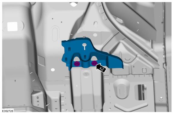
Remove the retainers and the front crossmember support mounting bracket.
-
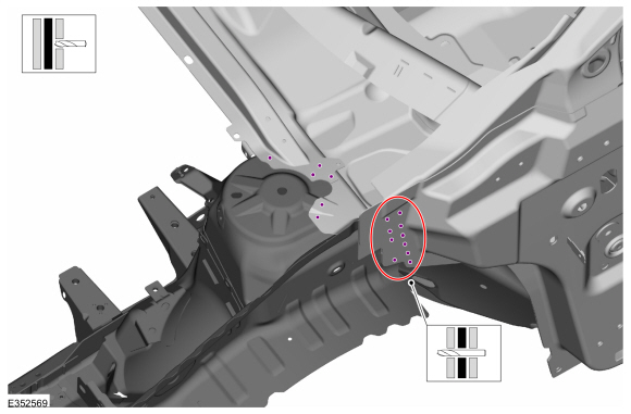
Remove the welds.
Use the General Equipment: Spot Weld Drill Bit
-
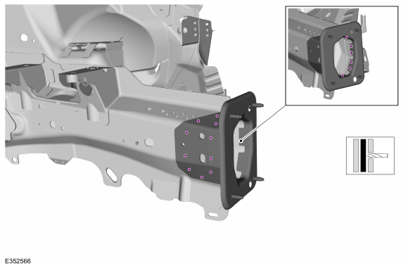
Remove the bumper bracket.
-
Remove the welds.
Use the General Equipment: Spot Weld Drill Bit
-
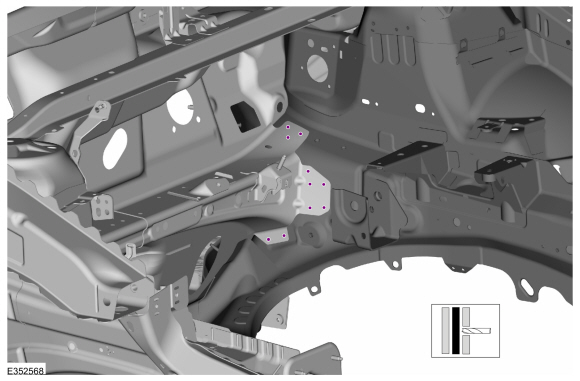
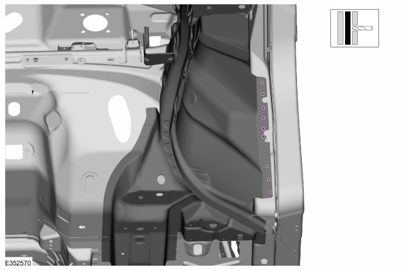
Remove the welds.
Use the General Equipment: Spot Weld Drill Bit
-
Remove the welds.
Use the General Equipment: Spot Weld Drill Bit
-
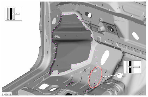
Remove the welds.
Use the General Equipment: Spot Weld Drill Bit
-
Remove the welds.
Use the General Equipment: Spot Weld Drill Bit
-
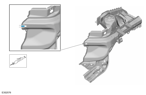
NOTE:
A partial section needs to be cut out at the apron panel to remove side member with the apron panel.
Carefully cut the partial section from the apron panel.
Use the General Equipment: Air Body Saw
-
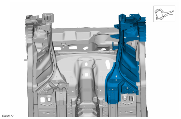
Remove the front side member and fender apron panel.
Installation
NOTE:
Left hand (LH) side shown, right hand (RH) side similar.
NOTE:
Factory welds may be substituted with resistance or metal
inert gas (MIG) plug welds. Resistance welds may not be placed directly
over original location. They must be placed adjacent to original
location and match factory welds in quantity. Metal inert gas (MIG) plug
welds must equal factory welds in both location and quantity.
NOTE:
Adequately protect all adjacent areas against cutting, grinding and welding procedures.
-
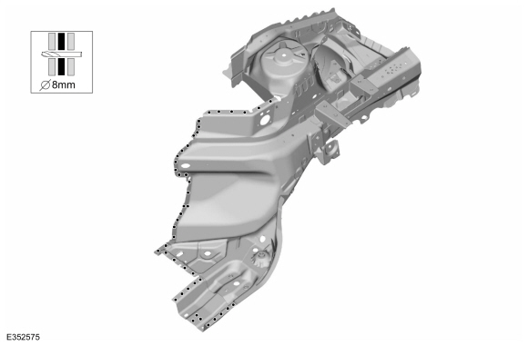
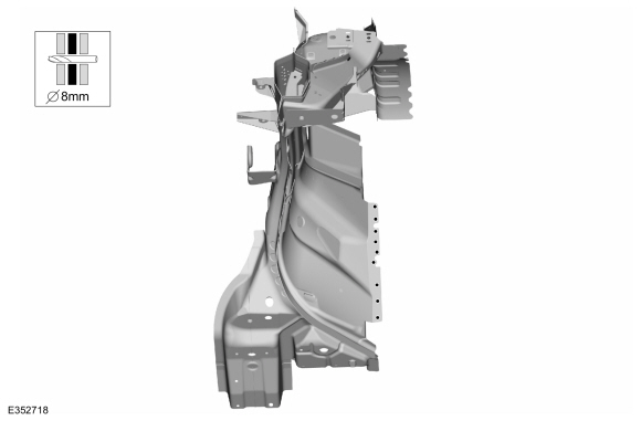
Drill plug welds holes in replacement panel.
Use the General Equipment: 8 mm Drill Bit
-
Drill plug welds holes in replacement panel.
Use the General Equipment: 8 mm Drill Bit
-
NOTE:
A partial section needs to be cut out at the apron panel to enable installation of the side member.
Carefully cut the partial section from the apron panel.
Use the General Equipment: Air Body Saw
-
Install,properly position and clamp the front side member and fender apron panel.
Use the General Equipment: Locking Pliers
-
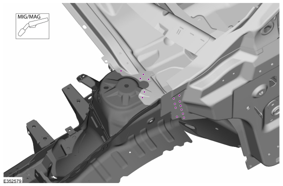
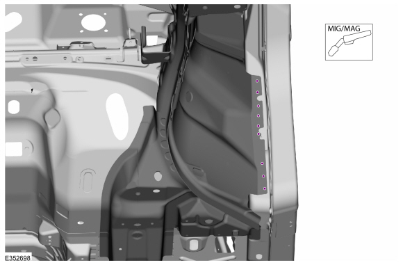
Install the welds.
Use the General Equipment: MIG/MAG Welding Equipment
-
Install the welds.
Use the General Equipment: MIG/MAG Welding Equipment
-
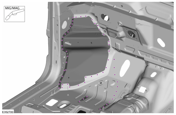
Install the welds.
Use the General Equipment: MIG/MAG Welding Equipment
-
Install the welds.
Use the General Equipment: MIG/MAG Welding Equipment
-
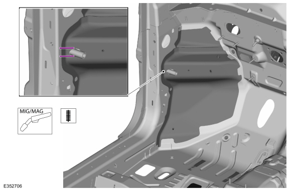
Install the seam weld as indicated.
Use the General Equipment: MIG/MAG Welding Equipment
-
Install the welds.
Use the General Equipment: MIG/MAG Welding Equipment
-
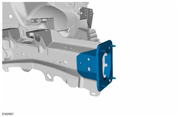
Install,properly position and clamp the bumper bracket.
Use the General Equipment: Locking Pliers
-
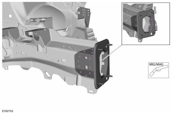
Install the welds.
Use the General Equipment: MIG/MAG Welding Equipment
-
Metal finish as required using typical metal finishing techniques.
-
Sealing work: All areas must be sealed to production level.
Material: Seam Sealer
/ TA-2-B, 3M™ 08308, LORD Fusor® 803DTM
-
Refinish using a Ford approved paint system.
-
Restore corrosion protection.
Refer to: Corrosion Prevention (501-25 Body Repairs - General Information, General Procedures).
-
Reosition the carpeting and wiring harness to original location.
-
Position the front crossmember support mounting bracket and install the retainers.
Torque:
35 lb.ft (48 Nm)
 |
|
-
Install the following items:
-
Install the restraints control module.
Refer to: Restraints Control Module (RCM) (501-20B Supplemental Restraint System, Removal and Installation).
-
Install the instrument panel.
Refer to: Instrument Panel (501-12 Instrument Panel and Console, Removal and Installation).
-
On both side.
Install the front seat.
Refer to: Front Seat (501-10A Front Seats, Removal and Installation).
-
Install the front impact severity sensor.
Refer to: Front Impact Severity Sensor (501-20B Supplemental Restraint System, Removal and Installation).
-
Install the radiator.
Refer to: Radiator (303-03A Engine Cooling - 2.0L EcoBoost (184kW/250PS) – MI4, Removal and Installation).
Refer to: Radiator (303-03B Engine Cooling - 2.7L EcoBoost (238kW/324PS), Removal and Installation).
-
Install the engine.
Refer to: Engine (303-01A Engine - 2.0L EcoBoost (184kW/250PS) – MI4, Installation).
Refer to: Engine (303-01B Engine - 2.7L EcoBoost (238kW/324PS), Installation).
-
Install the fender apron panel reinforcement.
Refer to: Fender Apron Panel Reinforcement (501-27 Front End Sheet Metal Repairs, Removal and Installation).
-
Repower the SRS .
Refer to: Supplemental Restraint System (SRS) Repowering (501-20B Supplemental Restraint System, General Procedures).
Special Tool(s) /
General Equipment
Resistance Spotwelding Equipment
Spherical Cutter
Grinder
MIG/MAG Welding Equipment
Spot Weld Drill Bit
Locking Pliers
Removal
Restore the vehicle to pre-accident dimensions, if required...
Special Tool(s) /
General Equipment
Resistance Spotwelding Equipment
Spherical Cutter
Air Body Saw
8 mm Drill Bit
MIG/MAG Welding Equipment
Spot Weld Drill Bit
Locking Pliers
Materials
Name
Specification
Seam SealerTA-2-B, 3M™ 08308, LORD Fusor® 803DTM
-
Removal
NOTE:
This procedure is intended for sectioning a small portion of t..
Other information:
Checking the Tire Pressures
Safe operation of your vehicle requires
that your tires are properly inflated.
Remember that a tire can lose up to half
of its air pressure without appearing flat.
Every day before you drive, check your
tires. If one looks lower than the others,
use a tire gauge to check the pressure
of all tires and adjust if required.
At least once a month and before long
trip..
How Do Personal Profiles Work
This feature allows you to create multiple
personal profiles enabling users to
personalize vehicle’s settings such as seats
and mirrors, as well as non-positional settings
like radio, navigation, driver assist system
settings. Positional settings are saved by
holding a memory seat button.
Non-positional settings are saved you
change a setting while a profile..
Categories
WARNING: If the tire pressure
monitor sensor becomes damaged it may
not function.
Note: The use of tire sealant may damage
your tire pressure monitoring system and
should only be used in roadside
emergencies. If you must use a sealant, use
the Tire Mobility Kit sealant. Replace the tire
pressure monitoring system sensor and
valve stem on the wheel by an authorized
dealer after use of the sealant.
Note: The tire pressure monitoring system
indicator light will illuminate when the spare
tire is in use. To restore the full function of
the monitoring system, all road wheels
equipped with tire pressure monitoring
sensors must be mounted on the vehicle.
If you get a flat tire while driving, do not apply
the brake hea
read more
.jpg)
.jpg)
.jpg)
.jpg)
.jpg)

 Fender Apron Panel Reinforcement. Removal and Installation
 Front Side Member Section. Removal and Installation