Lincoln Nautilus: Climate Control System - General Information / Heater Core Leak Check. General Procedures
Lincoln Nautilus 2018-2026 Service Manual / Electrical / Climate Control System / Climate Control System - General Information / Heater Core Leak Check. General Procedures
Inspection
-
NOTE: A coolant leak in the heater hose could follow the heater core tube to the heater core and appear as a leak in the heater core.
Inspect for evidence of coolant leakage at the heater hose to heater core attachments.
-
NOTE: Spring-type clamps are installed as original equipment. Installation and overtightening of nonspecified clamps can cause leakage at the heater hose connection and damage the heater core.
Check the integrity of the heater hose clamps.
-
Drain the coolant from the cooling system. Refer to
Cooling System Draining, Filling, and Bleeding procedure in Group 303.
-
Disconnect the heater hoses from the heater core.
-
Install a short piece of heater hose, approximately 101 mm (4 in) long on each heater core tube.
-
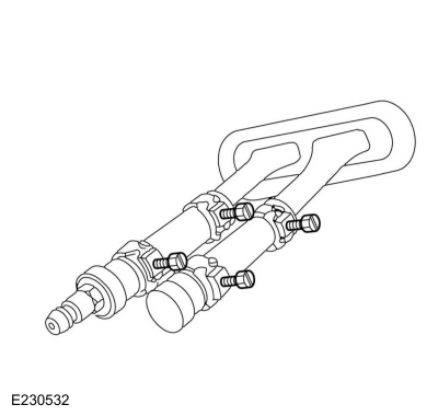
Fill the heater core and heater hoses with water and
install the plug (221373) and the adapter (221374) from the Pressure
Test Kit. Secure the heater hoses, plug and adapter with hose clamps.
 |
-
Attach the pump and gauge assembly from the Pressure Test Kit to the adapter.
-
Access the Pressure Test Kit Service Tools.
Refer to: Climate Control Tools and Equipment (412-00 Climate Control System - General Information, General Procedures).
-
Access the Pressure Test Kit Service Tools.
-
Close the bleed valve at the base of the gauge. Pump 138 kPa (20 psi) of air pressure into the heater core.
-
Observe the pressure gauge for a minimum of 3 minutes.
-
If the pressure drops, check the heater hose connections
to the heater core tubes for leaks. If the heater hoses do not leak,
replace the heater core. Refer to the appropriate heater core removal
and installation procedure in Group 412-00.
 Fluorescent Dye Leak Detection. General Procedures
Leak detection
Review next note for important refrigerant system dye information.
NOTE:
Fluorescent refrigerant system dye is added to the
refrigerant system at the factory to assist in refrigerant system leak
diagnosis using a Rotunda-approved UV
lamp...
 Refrigerant Identification Testing. General Procedures
Activation
NOTE:
Use Refrigerant Identification Equipment to identify
gas samples taken directly from the refrigeration system or storage
containers prior to recovering or charging the refrigerant system...
Other information:
Lincoln Nautilus 2018-2026 Service Manual: Windshield Wiper Motor. Removal and Installation
Removal NOTE: Removal steps in this procedure may contain installation details. Remove the wiper linkage assembly. Refer to: Wiper Linkage Assembly (501-16 Wipers and Washers, Removal and Installation). NOTICE: Be careful not to damage the link seals during removal...
Lincoln Nautilus 2018-2026 Service Manual: Noise, Vibration and Harshness (NVH). Diagnosis and Testing
Special Tool(s) MASTERTECH MTS-4000 ANALYZER257-00018 EngineEAR107-R2100Chassis EarsJSP97170 Squeak And Rattle Kit164-R4900 Ultrasonic Leak Detector134-R0135 Diagnostic Theory The shortest route to an accurate diagnosis results from: System knowledge, including comparison with a known good system...
Categories
- Manuals Home
- 1st Generation Nautilus Owners Manual
- 1st Generation Nautilus Service Manual
- Switching the Lane Keeping System On and Off. Switching the Lane Keeping System Mode
- Drive Mode Control
- Locating the Pre-Collision Assist Sensors
- New on site
- Most important about car
Opening and Closing the Hood
Opening the Hood
Copyright © 2026 www.linautilus.com