Lincoln Nautilus: Lane Keeping System / Image Processing Module A (IPMA). Removal and Installation
Removal
NOTE: Removal steps in this procedure may contain installation details.
-
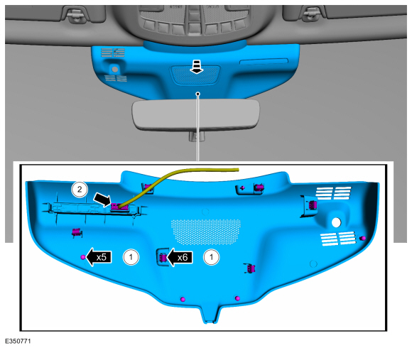
Remove the IPMA cover.
-
Release the tabs and clips from the IPMA cover.
-
Disconnect the wiring harness electrical connector and remove the IPMA cover.
-
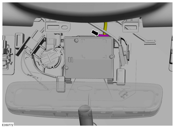
Release the tabs and clips from the IPMA cover.
 |
-
Disconnect the electrical connector.
 |
-
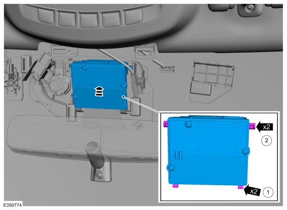
Remove the IPMA .
-
Remove the upper tabs.
-
Remove the lower tabs.
-
Remove the upper tabs.
.jpg) |
Installation
-
Install the IPMA .
-
Install the lower tabs.
-
Install the upper tabs.
-
Install the lower tabs.
 |
-
To install, reverse the removal procedure.
-
NOTE: This step is only necessary when installing a new component.
-
If a new IPMA has been installed, using a diagnostic scan tool,
complete the PMI process for the IPMA following the on-screen
instructions.
-
If a new IPMA has been installed, carry out the camera alignment using a scan tool.
-
If a new IPMA has been installed, using a diagnostic scan tool,
complete the PMI process for the IPMA following the on-screen
instructions.
 Lane Keeping System. Diagnosis and Testing
DTC Chart(s)
Diagnostics in this manual assume a certain skill level and knowledge of Ford-specific diagnostic practices. REFER to: Diagnostic Methods (100-00 General Information, Description and Operation)...

Other information:
Lincoln Nautilus 2018-2026 Owners Manual: Switching Active Park Assist On and Off. Entering a Parallel Parking Space
Switching Active Park Assist On and Off Press the active park assist button, then press the active park assist icon on the touchscreen to bring up full screen notifications. Press the soft keys on the touchscreen to switch between the parallel park in, perpendicular park in, or parallel park out parking modes. Cancelling Active Park Assist To cancel parking assistance at any time, shift o..
Lincoln Nautilus 2018-2026 Service Manual: Driver Temperature Door Actuator. Removal and Installation
Removal Remove the brake pedal and bracket assembly. Refer to: Brake Pedal and Bracket (206-06 Hydraulic Brake Actuation, Removal and Installation). Disconnect the electrical connector, remove the retainers. Position aside the wire harness and remove the driver side temperature door actuator. Installation To install, reverse the removal proc..
Categories
- Manuals Home
- 1st Generation Nautilus Owners Manual
- 1st Generation Nautilus Service Manual
- Folding the Exterior Mirrors - Vehicles With: Manual Folding Mirrors. Folding the Exterior Mirrors - Vehicles With: Power Folding Mirrors
- Switching the Lane Keeping System On and Off. Switching the Lane Keeping System Mode
- Massage Seats
- New on site
- Most important about car
Traction Control
How Does Traction Control Work
If your vehicle begins to slide, the system applies the brakes to individual wheels and, when needed, reduces power at the same time. If the wheels spin when accelerating on slippery or loose surfaces, the system reduces power in order to increase traction.
Switching Traction Control On and Off
WARNING: The stability and traction control light illuminates steadily if the system detects a failure. Make sure you did not manually disable the traction control system using the information display controls or the switch. If the stability control and traction control light is still illuminating steadily, have the system serviced by an authorized dealer immediately. Operating your vehicle with the traction co