Lincoln Nautilus: Module Configuration / Module Programming. General Procedures
Check
NOTE: Perform the following pre-checks to make sure module programming completes without errors.
-
Start the programming session in Key OFF, Engine OFF and prior to initiating programming, turn to KOEO .
-
Make sure the vehicle battery is fully charged or is
connected to a battery charger. The battery state of charge should be
12.6 - 13.6 volts during vehicle programming.
-
NOTE: A good internet connection is necessary.
Inspect the VCM II, VCMM or later level device and cables for damage. Make sure cables remain connected throughout the programming procedure.
-
Turn off all unnecessary accessories, such as radio, A/C , climate controlled seats, headlamps, interior and demand lamps.
-
Disconnect any aftermarket accessories, such as remote start, security alarm and power inverter.
-
For Plug-in hybrid and electric vehicles, disconnect the external charge cord from the charge port.
-
Disable Microsoft Windows sleep mode, screensaver and hibernation modes.
-
NOTE: If the diagnostic software does not load or if the vehicle cannot be identified properly.
Make sure there is a good internet connection and the VCM II, VCMM or later level device is properly connected to the DLC .
Programming
-
NOTE: If a new module is being installed, install the new module before carrying out the following procedure.
- If replacing the module do not connect the new module to a Wi-Fi network before completing the scan tool module replacement programming as it may cause programming concerns.
- This programming procedure deletes any phones that are paired with the SYNC system when programming the APIM .
- To prevent time-out errors and minimize programming time, a wired internet connection is strongly recommended when programming.
- Make sure the FDRS version and patch software levels are up to date.
-
Connect the diagnostic scan tool to a power supply. The
length of time required for programming may extend past the duration of
the diagnostic scan tool.
-
Connect the diagnostic scan tool to the DLC .
-
Log into FDRS .
-
Identify/enter the vehicle being programmed on FDRS .
-
NOTE: Vehicle information is automatically retrieved by the diagnostic software and a Network Test is run. Vehicle identification data appears on the screen when this is complete.
Click 'Read VIN from Vehicle' or manually enter the VIN .
-
NOTE: Available modules are shown on the LH side of the screen, and available procedures are listed on the RH side of the screen. Modules that are communicating are highlighted in green.
Select Toolbox tab.
-
NOTE: If a module is integrated within another module, both modules will automatically program during this process. For example, if the ACM is selected, the DACMC (if integrated with the ACM ) is also programmed.
From the list on the LH side of the screen, select the module that requires a programming procedure to be completed.
-
There are 3 types of module programming available:
-
Programmable Module Installation (PMI)—When
the module is replaced, this type of programming carries out the
required provisioning (restores software for newly installed hardware).
-
Module configuration — Downloads
configuration data to the module. The module may also be programmed,
depending on current software level, when this option is selected.
-
Software Update— Updates the module and
any currently installed applications to the latest software levels. This
option is not available if the module is already at the latest level.
-
Programmable Module Installation (PMI)—When
the module is replaced, this type of programming carries out the
required provisioning (restores software for newly installed hardware).
-
From the list on the RH side of the screen, select PMI Software Update or Module Configuration.
-
NOTE: Do not disconnect the VCM from the DLC during the module programming process unless directed by the diagnostic scan tool on-screen prompts.
Follow all on-screen instructions carefully.
-
After programming is complete, "Programming has been successfully completed" displays.
Programming
NOTE: If updating using a USB memory device.
-
Connect a battery charger to the vehicle 12V battery. Set the charger to maintain 12.6 - 13.6 volts.
-
Connect the VCM II, VCMM or later level device to the vehicle DLC and the diagnostic scan tool USB port.
-
Log into FDRS .
-
NOTE: Vehicle information is automatically retrieved by the diagnostic software and a Network Test is run. Vehicle identification data appears on the screen when this is complete.
Click 'Read VIN from Vehicle' or manually enter the VIN .
-
NOTE: Available modules are shown on the LH side of the screen, and available procedures are listed on the RH side of the screen. Modules that are communicating are highlighted in green.
Select Toolbox tab.
-
NOTE: If the module is already at the latest software level, the software update application will not be available in the diagnostic scan tool.
If replacing the module, download and run the PMI . If the module is not being replaced but is receiving a software update in accordance with a TSB or service publication, download and run the software update application for the target module.
-
Close all doors or mechanically latch the door to simulate a closed door.
-
Follow the on-screen prompts to complete the PMI .
-
On-screen prompts are displayed to inform that a USB is required to complete the process.
-
Follow the on-screen instructions to download the required software to
the USB memory device and upload to the vehicle though the vehicle USB
port.
-
Once the USB memory device is connected to the media hub or USB port,
the software update will automatically install. The USB memory device
transfers the data through the USB cable to the APIM . The APIM
transfers the data to the GWM where it is distributed to the receiving
module over the Ethernet network.
-
It is advised that the USB
memory device remain connected to the vehicle for a minimum of 2
minutes after the progress bar displayed on the vehicle display screen
has reached 100%, to ensure the upload has completed fully.
-
If an error occurs during the USB
programming process an error message is displayed on the vehicle
display screen indicating an error has occurred and displays an error
number relating to the type of error that occurred. REFER to the Error
Condition Table below for a description and action to be taken, if an
error message is displayed.
Error Condition Table
Vehicle display screen Error Message Cause Action USB Error 1 CacheFull Delete all contents on the USB memory device/ Format the USB memory device. Re-run the PMI routine with the diagnostic scan tool and re attempt the PMI . If the PMI fails again, attempt a CAN flash, following the diagnostic scan tool on-screen instructions. USB Error 2 Manifestinvalid Delete all contents on the USB memory device/ Format the USB memory device. Re-run the PMI routine with the diagnostic scan tool and re attempt the PMI . If the PMI fails again, attempt a CAN flash, following the diagnostic scan tool on-screen instructions. USB Error 3 InstallationPackageError Delete all contents on the USB memory device/ Format the USB memory device. Re-run the PMI routine with the diagnostic scan tool and re attempt the PMI . If the PMI fails again, attempt a CAN flash, following the diagnostic scan tool on-screen instructions. USB Error 4 USBRemoved - Make sure the USB memory device is installed in the vehicle until the vehicle display screen indicates programming was successful and the USB memory device can be removed.
- Using a diagnostic scan tool carry out the APIM self -test and verify there are no USB cable or media hub related Diagnostic Trouble Codes (DTCs).
- Verify USB / media hub functionality by using the MIT , a mobile phone connected via a USB charge cord and/or a USB memory device with media files loaded.
- Remove and reinsert the USB memory device and retry programming.
- Attempt programming with a different USB memory device.
USB Error 5 InstallSignature Delete all contents on the USB memory device/ Format the USB memory device. Re-run the PMI routine with the diagnostic scan tool and re attempt the PMI . If the PMI fails again, attempt a CAN flash, following the diagnostic scan tool on-screen instructions. USB Error 6 RebootReset - Do not perform a master reset or SYNC hard reset during the USB programming. Make sure active resets are finished and the SYNC system has rebooted before re-attempting the USB programming.
- Test the vehicle's 12 volt vehicle battery using approved diagnostic battery testers. Fully recharge or replace the battery per the test results. Complete the Battery Monitoring System (BMS) reset after the battery service, if directed by the workshop manual procedure. Retry the programming.
USB Error 7 USBReadError - Make sure the USB memory device is installed in the vehicle until the vehicle display screen indicates programming was successful and the USB can be removed.
- Using a diagnostic scan tool carry out the APIM self -test and verify there are no USB cable or media hub related Diagnostic Trouble Codes (DTCs).
- Verify USB / media hub functionality by using the MIT , a mobile phone connected via a USB charge cord and/or a USB memory device with media files loaded.
- Remove and reinsert the USB memory device and retry programming.
- Attempt programming with a different USB memory device.
USB Error 8 USBWriteError - Make sure the USB memory device used for the update is a 32GB, Exfat formatted USB memory device.
- Attempt programming with the correctly formatted USB memory device or a different 32GB, Exfat formatted USB memory device.
USB Error 9 BatVoltageLow Test the vehicle 12 volt battery using approved diagnostic battery testers. Fully recharge or replace the battery per the test results. Complete the Battery Monitoring System (BMS) reset after the battery service, if directed by the workshop manual procedure. Retry the programming. USB Error 10 USBWrongFiles Make sure the correct files have been downloaded to the USB memory device. USB Error 11 VehicleModes Make sure the vehicle's ignition is in the key on, engine off state. Verify the vehicle is in park/neutral. USB Error 12 eCallPhone Verify that any paired mobile phones are not making a Bluetooth connected call through the SYNC system. USB Error 13 Crash Using a diagnostic scan tool carry out the OCSM and RCM self-test. Verify there are no crash related Diagnostic trouble codes (DTCs) stored. Diagnose any related codes and reattempt to reprogram the vehicle. USB Error 14 IgnitionCycle - Make sure the vehicle ignition remains in the key on, engine off state during programming. The LED indicator on the ignition push button remains flashing when in key on, engine off state. Low battery state of charge or battery health may cause battery load shed strategies to shut the ignition off during programming.
- Test the 12-volt battery using an approved diagnostic battery tester. Fully recharge or replace the battery per the tester results. Once complete, carry out the Battery Monitor System (BMS) reset with the scan tool.
- Reattempt the programming.
USB Error 15 MasterReset Do not perform a master reset or SYNC hard reset during the USB programming. Make sure active resets are finished and the SYNC system has rebooted before re-attempting the USB programming.
Recovery
NOTE: Perform the following steps when programming has resulted in a blank module.
-
Disconnect the VCM II, VCMM or later level device from the DLC and PC.
-
Launch FDRS and log in.
-
In the Device Manager window that populates, select CANCEL.
-
Select the appropriate VIN from the Vehicle Identification menu or use Manual VIN Entry and select GO.
-
In the Vehicle Communication Device Not Detected window
that populates, select CONTINUE. If a Device Explorer window populates,
select CANCEL.
-
After the session has started, reconnect the VCM II/ VCMM to the DLC
and the PC. The VCM II/ VCMM or later level device icon should turn
green in the bottom right corner of the screen. If it does not,
troubleshoot the FDRS to VCM II, VCMM or later level device connection.
-
In the Toolbox menu, navigate to the failed module and Download/Run PMI
. Follow the on-screen prompts. When asked if the original module is
installed, select NO and continue through the installation application.
-
Once programming has completed, a screen may list
additional steps required to complete the programming process. Make sure
all applicable steps are followed in order.
 Module Configuration - System Operation and Component Description. Description and Operation
System Operation
Programmable Module Installation (PMI)
PMI is a diagnostic scan tool process which configures settings in a new module. Data used for the PMI
process is automatically downloaded from the original module and
stored when a diagnostic scan tool session is started...

Other information:
Lincoln Nautilus 2018-2026 Service Manual: Module Controlled Functions - System Operation and Component Description. Description and Operation
System Operation Body Control Module (BCM) The BCM controls various systems by monitoring inputs from switches, sensors and network messages from other modules on the HS-CAN1 and from the GWM . Based on the inputs received, the BCM activates outputs. For example, the BCM monitors the headlamp switch position. Based on this input, the BCM may provide voltage to the exterior lamps. Batter..
Lincoln Nautilus 2018-2026 Service Manual: Instrument Panel Cluster (IPC) - Overview. Description and Operation
Overview IPC Item Description 1 LED low beam malfunction indicator 2 Lights on indicator 3 Stability-traction control disabled indicator (sliding car OFF icon) 4 Stability-traction control indicator (sliding car icon) 5 Auto high beam indicator 6 High beam indicato..
Categories
- Manuals Home
- 1st Generation Nautilus Owners Manual
- 1st Generation Nautilus Service Manual
- Changing the 12V Battery
- Folding the Exterior Mirrors - Vehicles With: Manual Folding Mirrors. Folding the Exterior Mirrors - Vehicles With: Power Folding Mirrors
- Massage Seats
- New on site
- Most important about car
Replacing the Rear Wiper Blades
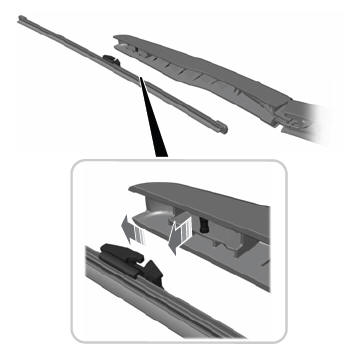
Note: Do not hold the wiper blade to lift the wiper arm.
Remove the wiper blade.