Lincoln Nautilus: Parking Aid - Vehicles With: Parking Aid Camera / Parking Aid - System Operation and Component Description. Description and Operation
System Operation
Rear Only Parking Aid Camera
System Diagram
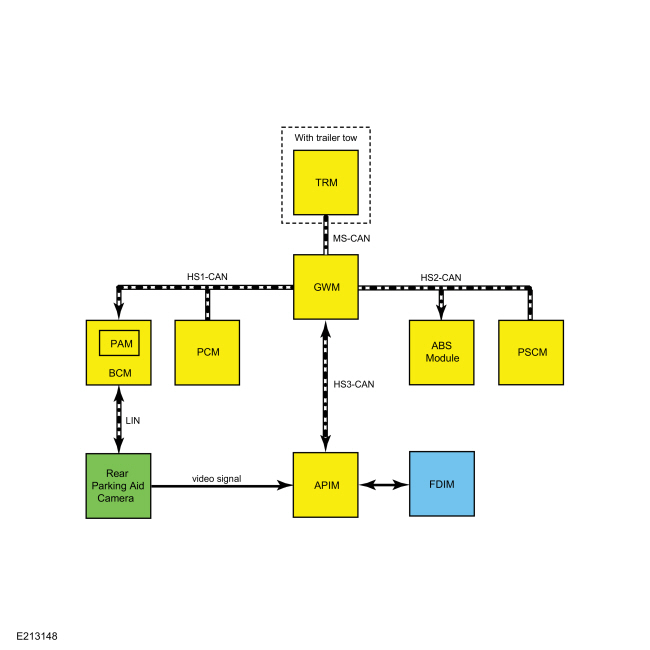
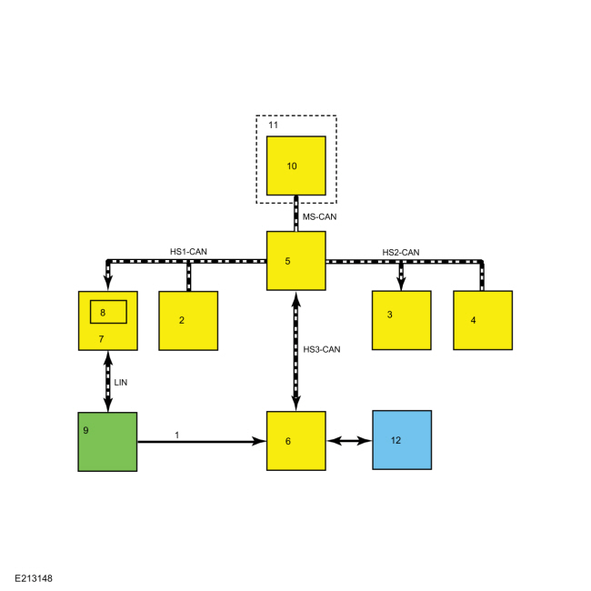
| Item | Description |
|---|---|
| 1 | Video signal |
| 2 | PCM |
| 3 | ABS Module |
| 4 | PSCM |
| 5 | GWM |
| 6 | APIM |
| 7 | BCM |
| 8 | PAM |
| 9 | Rear parking aid camera |
| 10 | TRM |
| 11 | With trailer tow |
| 12 | FDIM |
Network Message Chart
BCM Network Input Messages
| Broadcast Message | Originating Module | Message Purpose |
|---|---|---|
| Camera commands | APIM | Used to command the zoom level on and off based on driver inputs through the FDIM . |
| Gear lever position | PCM | Used to support the rear parking aid camera standby mode. Turns the camera image output on when reverse gear is selected. |
| Parking aid sensor data | PAM | Used to generate the visual highlights in the zone where an object is detected by the rear parking aid system. |
| Steering angle | ABS module | Used to generate the intended vehicle path for the active guideline feature. |
| Trailer lamp connected | TRM | Disables the guidelines and visual park aid alert when a trailer is electrically connected to the vehicle (if equipped with factory trailer tow). |
| Vehicle speed | PCM | Used to support the rear parking aid camera standby mode. Turns the camera image output off when vehicle speed is 16 km/h (10 mph) or greater and turns the camera image output on when the vehicle speed is 8 km/h (5 mph) or less. |
ABS Module Network Input Messages
| Broadcast Message | Originating Module | Message Purpose |
|---|---|---|
| Steering wheel angle sensor data | PSCM | The ABS module uses the steering angle sensor data to generate the steering angle message that is sent to the BCM to support the active guideline feature. |
APIM Network Input Messages
| Broadcast Message | Originating Module | Message Purpose |
|---|---|---|
| Camera status | BCM | Used to display the current status for active guidelines and visual park aid alert. |
| Gear lever position | PCM | Used to enable the video display when reverse gear is selected. |
| Parking aid sensor data | PAM | Used to generate the visual highlights in the zone where an object is detected by the rear parking aid system. |
| Vehicle speed | PCM | When the video delay feature is turned on, this message is used to turn the rear camera display off after the vehicle speed exceeds a preset threshold. |
Image Display
NOTE: The liftgate must be fully closed for correct operation of the rear parking aid camera system.
The rear parking aid camera image is displayed by the FDIM when reverse gear is selected. To determine the selector lever position and enable the camera display, the PCM sends the gear position message to the GWM on the HS-CAN1 . The GWM then sends the message to the APIM via the HS-CAN3 .
The camera is on any time it receives voltage (when the ignition is ON), but a video signal is only generated under certain conditions. When reverse gear is selected, the camera continuously generates a video signal. When any gear except reverse is selected, the camera turns the video signal off when the vehicle speed reaches 16 km/h (10 mph), and turns the video signal on when vehicle speed falls below 8 km/h (5 mph). If the camera is not configured properly, some features may be inoperative. The camera sends the video signal on shielded twisted pair wires to the APIM , which displays the image on the FDIM .
The following parking aid camera system features are driver selectable:
- Visual park aid alert — assists the driver to visually see the object causing the parking aid system to sound.
- Manual zoom — allows the driver to manually zoom the image.
- Video delay — allows the driver to see the image behind the vehicle after the vehicle is shifted out of reverse into any gear other than park.
The following camera system features are not driver selectable:
- Fixed guidelines — assists the driver with aligning the vehicle with an object.
- Active guidelines — displays the intended path of the vehicle based upon steering wheel input.
The FDIM settings menu is used to turn the visual park aid alert and video delay on and off. The visual park aid alert and video delay features are generated within the APIM .
To turn the manual zoom feature on and off, the driver uses an on screen button located on the FDIM while in reverse. The driver generated commands originate at the FDIM , which is hardwired to the APIM . The APIM sends the driver generated commands over the HS-CAN3 to the GWM . The GWM then sends the commands to the BCM on the HS-CAN1 . The BCM sends the zoom command to the rear parking aid camera via the LIN circuit. The zoom is generated by the rear parking aid camera.
The fixed and active guidelines are generated by the rear parking aid camera and are not selectable by the driver.
LIN Communication
The BCM and the rear parking aid camera communicate via a LIN circuit which is a dedicated single wire communication network. The BCM is the master module on the LIN , and it sets and stores Diagnostic Trouble Codes (DTCs) for the rear parking aid camera and the communication network.
The messages sent from the BCM to the camera are:
- Camera configuration data
- Display manual zoom request
- Guideline on/off request
- Liftgate ajar status
- Trailer connection status (if equipped with factory trailer tow)
- Steering angle
- Standby enable/disable request
The messages sent from the camera to the BCM are:
- Camera status
- Display zoom status
- Camera part number data
- Guideline status
Visual Park Aid Alert
NOTE: The on-screen alert transitions may not match changes in the audible parking aid alert tone frequency.
The visual park aid alert feature displays a visual highlight in the zone where an object has been detected by the rear parking aid system. This feature utilizes the parking aid sensor data from the PAM to generate the visual highlights on the video image. When reverse gear is selected and an object is detected by a rear parking aid sensor, the parking aid sensor data message from the PAM is used by the APIM to generate the alert.
If the visual park aid alert feature is enabled, the feature is still operational even if the rear parking aid system has been disabled by the driver.
Fixed Guidelines
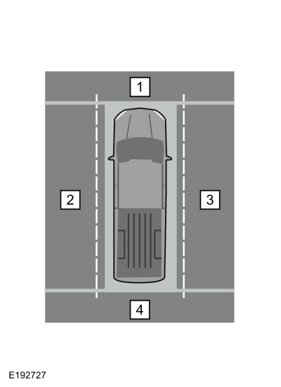
NOTE: The color-coded lines cannot indicate accurate or consistent distances between the rear of the vehicle and objects shown in the video image. This normal condition is due to variances in vehicle ride height, including, but not limited to, vehicle loading.
The video camera fixed guidelines feature displays guidelines on top of the video image to assist the driver with alignment of the vehicle. A dashed line on the displayed image represents the center of the vehicle and 3 color-coded lines (red, yellow, green) identify different zones between the rear of the vehicle and objects.
The guidelines are not shown when reverse is not selected (video delay active).
Fixed guidelines are not shown when the liftgate is open.
If the vehicle is equipped with a factory TRM , the fixed guidelines are not shown when a trailer is electrically connected to the vehicle.
Active Guidelines
NOTE: If the battery has been disconnected or discharged, or a module is disconnected or replaced, the active guidelines may be inoperative until the vehicle is driven on a flat and smooth road at 32 km/h (20 mph) or more, with hands placed loosely on the steering wheel and minimal steering correction for approximately 30 seconds.
If the guidelines remain inoperative, it may be necessary to disconnect the battery for 5 minutes with the driver's door open, then drive the vehicle for 8 kilometers (5 miles) in normal city driving before performing the procedure described above.The active guidelines feature displays dynamic guidelines that correspond to the projected path of vehicle travel, based on the current steering angle. Several modules are involved in generating the steering angle data used to support the active guidelines. The PSCM monitors the steering angle sensor and sends the steering wheel angle sensor data to the ABS module via the HS-CAN2 . The ABS module uses this message from the PSCM to generate the steering angle message that is sent to the GWM on the HS-CAN2 . The GWM then sends the message to the BCM via the HS-CAN1 . The BCM sends the steering angle data to the rear parking aid camera via the LIN circuit. The camera uses this data to generate the active guidelines over the video image.
If the steering wheel is in the straight-ahead position or if the liftgate is open, the active guidelines are not shown.
The guidelines are not shown when reverse is not selected (video delay active).
If the vehicle is equipped with a factory TRM , the active guidelines are not shown when a trailer is electrically connected to the vehicle.
Manual Zoom
The manual zoom feature is generated by the rear parking aid camera and has one level of zoom. If the manual zoom feature is on and the vehicle is shifted out of reverse gear, the manual zoom feature is disabled and must be re-enabled the next time reverse gear is selected. When the driver turns the zoom on or off at the FDIM , the zoom command is sent through HS-CAN3 to the GWM then over HS-CAN1 to the BCM . The BCM then sends the manual zoom request message to the rear parking aid camera via the LIN circuit and the camera then turns the zoom on or off.
Video Delay
When the video delay is turned on, the display keeps the rear video display enabled after the transmission is shifted out of reverse gear into any gear other than park, until the vehicle speed reaches 8 km/h (5 mph). With the delay off (default), the image displays until the transmission is shifted out of reverse gear.
360 Degree View Camera
System Diagram
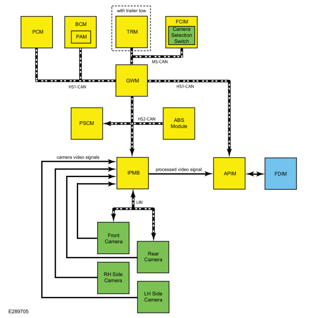
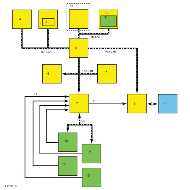
| Item | Description |
|---|---|
| 1 | BCM |
| 2 | processed video signal |
| 3 | PAM |
| 4 | PCM |
| 5 | APIM |
| 6 | PSCM |
| 7 | IPMB |
| 8 | GWM |
| 9 | TRM |
| 10 | with trailer tow |
| 11 | camera video signals |
| 12 | FCIM |
| 13 | Front camera |
| 14 | Rear camera |
| 15 | LH side camera |
| 16 | RH side camera |
| 17 | ABS module |
| 18 | Camera selection switch |
| 19 | FDIM |
Network Message Chart
IPMB Network Input Messages
| Broadcast Message | Originating Module | Message Purpose |
|---|---|---|
| Camera commands | APIM | Used to command the visual park aid alert and zoom level on and off based on driver inputs through the FDIM . |
| Camera selection switch status | FCIM | Used to switch the 360 degree views or rear parking aid camera views dependent upon the transmission gear selection. |
| Driver door ajar status | BCM | Used to generate the door ajar icon on the image when the LH front or rear door is ajar. |
| Gear lever position | PCM | Used to enable the front or rear camera views based on the current gear selection. |
| Liftgate ajar status | BCM | Disables the guidelines and visual park aid alert when the liftgate is open. |
| Parking aid sensor data | PAM | Used to generate the visual highlights in the zone where an object is detected by the parking aid system. |
| Passenger door ajar status | BCM | Used to generate the door ajar icon on the image when the RH front or rear door is ajar. |
| Steering angle | ABS module | Used to generate the intended vehicle path for the active guideline feature. |
| Trailer lamp connected | TRM | Disables the guidelines and visual park aid alert when a trailer is electrically connected to the vehicle (if equipped with factory trailer tow). |
| Vehicle speed | PCM | Used to support the front and rear camera standby mode. Turns the camera image output off when vehicle speed is 16 km/h (10 mph) or greater and turns the camera image output on when the vehicle speed is 8 km/h (5 mph) or less. |
ABS Module Network Input Messages
| Broadcast Message | Originating Module | Message Purpose |
|---|---|---|
| Steering wheel angle sensor data | PSCM | The ABS module uses the steering angle sensor data to generate the steering angle message that is sent to the IPMB to support the active guideline feature. |
APIM Network Input Messages
| Broadcast Message | Originating Module | Message Purpose |
|---|---|---|
| Camera status | IPMB | Used to enable the video display when the camera selection switch is pressed. |
| Gear lever position | PCM | Used to enable and disable the video display based on the current gear selection. |
| Parking aid sensor data | PAM | Used to generate the visual highlights in the zone where an object is detected by the rear audible parking aid system. |
| Vehicle speed | PCM | When the video delay feature is turned on, this message is used to turn the rear camera display off after the vehicle speed exceeds a preset threshold. |
Image Display
NOTE: The liftgate and doors must be fully closed for correct operation of the 360 degree view camera system.
The 360 degree view camera system is capable of generating several different views using the front, rear, LH side and RH side cameras, and the IPMB . The IPMB processes the video signals from the 4 cameras and generates the appropriate views that are displayed on the FDIM . The views that are displayed are determined by the transmission gear selector position.
When the ignition is ON and reverse gear is selected, the rear camera views are shown on the FDIM . The Rear 360 + Normal view is shown first. Subsequent presses of the camera selection switch when reverse gear is selected allow the driver to cycle through the rear camera views in the following order:
| View order | View name | Description |
|---|---|---|
| 1 | Rear 360 + Normal | Contains the normal rear camera view, shown next to a 360 degree camera view. |
| 2 | Rear Normal | Provides an image of what is directly behind the vehicle. |
| 3 | Rear Split View | Provides an extended wide angle image of what is behind the vehicle. |
When the ignition is ON and any gear except reverse is selected, the front camera and 360 degree views are shown on the FDIM when the camera selection switch is pressed. The front images are available until the vehicle speed reaches 10 km/h (6 mph). The Front 360 + Normal view is shown first. Subsequent presses of the camera selection switch allow the driver to cycle through the front camera views in the following order:
| View order | View name | Description |
|---|---|---|
| 1 | Front 360 + Normal | Contains the normal front camera view, shown next to a 360 degree camera view. |
| 2 | Front Normal | Provides an image of what is directly in front of the vehicle. |
| 3 | Front Split View | Provides an extended wide angle image is what is in front of the vehicle. |
To enable the front or rear camera displays, the IPMB monitors the camera selection switch (integral to the FCIM ), gear position and vehicle speed messages. The PCM sends the gear position and vehicle speed messages to the GWM through the HS-CAN1 and the FCIM sends the camera selection switch status message to the GWM through the MS-CAN . The GWM then sends the messages to the IPMB via HS-CAN2 .
All camera views are generated by the IPMB , using the video signals from one or more of the cameras. The video signals are sent from the cameras to the IPMB through twisted pair, shielded circuits. The IPMB processes the image(s) from the cameras and sends a single image with the desired view to the APIM .
360 Degree Image Composition
To generate the 360 degree view, the IPMB combines and aligns the images from all 4 cameras to produce a single overhead view that is displayed on the FDIM along with a front or rear camera view.
NOTE: When a camera or any body component that a camera is attached to is removed or adjusted, the 360 degree view camera alignment must be performed to create a 360 degree image.
Refer to: 360 Degree View Camera Alignment (413-13B Parking Aid - Vehicles With: Parking Aid Camera, General Procedures).
NOTE: F-150 shown, other vehicles similar.
| Item | Description |
|---|---|
| 1 | Front camera image |
| 2 | LH side camera image |
| 3 | RH side camera image |
| 4 | Rear camera image |
Camera Image Generation
The front and rear cameras are on any time they receive voltage (when the ignition is ON), but a video signal is only generated under certain conditions. When reverse gear is selected or the camera selection switch is pressed, the IPMB sends an enable request message to the front and rear cameras to turn the video signal output on. When any gear except reverse is selected, the IPMB sends a disable request message to the cameras to turn the video signal off when the vehicle speed reaches 16 km/h (10 mph), and sends an enable request message to turn the video signal on when vehicle speed falls below 8 km/h (5 mph). If the front or rear camera is not configured properly, some features and views may be inoperative.
The LH and RH side cameras are on and generating a video signal any time they receive voltage from the IPMB . The IPMB supplies voltage to the LH and RH side cameras when reverse gear is selected or the camera selection switch is pressed.
LIN Communication
The IPMB communicates with the front parking aid camera and rear parking aid cameras via a LIN circuit, which is a dedicated single wire communication network.
The messages sent from the IPMB to the front and rear cameras are:
- Camera view request
- Camera configuration data
- Display manual zoom request (rear camera only)
- Guideline on/off request (rear camera only)
- Standby enable/disable request
- Steering angle (rear camera only)
- Trailer connection status (if equipped with factory trailer tow)
The messages sent from the front and rear camera to the IPMB are:
- Camera view status
- Camera status
- Display zoom status (rear camera only)
- Camera part number data
- Guideline status (rear camera only)
Camera Features
The system supports several rear camera features to assist the driver.
The following features are driver selectable:
- Visual park aid alert — visually alerts the driver to objects causing the parking aid system to sound.
- Manual zoom — allows the driver to manually zoom the image.
- Video delay — allows the driver to see the image behind the vehicle after the vehicle is shifted out of reverse into any gear other than park.
The following features are not driver selectable:
- Fixed guidelines — displays guidelines to assist the driver with aligning the vehicle with an object.
- Active guidelines — displays the intended path of the vehicle based upon steering wheel input.
The system supports visual park aid alert on 360 + Normal and Normal views. Front and rear split view do not include visual park aid alert. For views that include the 360 degree overhead image, the visual park aid alert is generated by the IPMB . For views that do not include the 360 degree overhead image, the visual park aid alert feature is generated by the APIM .
To turn the manual zoom on and off, the driver generated commands originate at the FDIM , which is physically connected to the APIM . The commands are sent by the APIM to the IPMB via the HS-CAN3 , GWM and HS-CAN2 . The IPMB then sends the zoom command to the rear camera via the LIN circuit. The image is then zoomed in or out by the rear camera.
The video delay feature is controlled within the APIM .
The fixed and active guidelines are generated by the IPMB and are not selectable by the driver.
Visual Park Aid Alert
NOTE: The on-screen alert transitions may not match changes in the audible parking aid alert tone frequency.
NOTE: The visual park aid alert is not available on Front Split View and Rear Split View camera views.
The visual park aid alert feature displays a visual highlight in the zone where an object has been detected by the parking aid system. For views that include the 360 degree overhead image, the visual park aid alert is displayed as a color changing line around the perimeter of the 360 degree view overhead vehicle graphic. This visual park aid alert feature is generated by the IPMB . For views that do not include the 360 degree overhead image, the visual park aid alert feature is displayed as a vehicle icon in the upper part of the display. This icon is generated by the APIM . These features utilize the parking aid sensor data from the PAM to generate the visual highlights on the video image.
If the visual park aid alert feature is enabled, the feature is still operational even if the rear parking aid system has been disabled by the driver.
Fixed Guidelines
NOTE: The color-coded lines cannot indicate accurate or consistent distances between the rear of the vehicle and objects shown in the video image. This normal condition is due to variances in vehicle ride height, including, but not limited to, vehicle loading.
Fixed guidelines are only displayed on the rear camera image in Rear 360 + Normal and Rear Normal views.
The video camera fixed guidelines feature displays guidelines on top of the rear video image to assist the driver with alignment of the vehicle. A dashed line on the displayed image represents the center of the vehicle and 3 color-coded lines (red, yellow, green) identify different zones between the rear of the vehicle and objects.
Fixed guidelines are not shown when the liftgate is open.
If the vehicle is equipped with a factory TRM , the fixed guidelines are not shown when a trailer is electrically connected to the vehicle.
Active Guidelines
NOTE: If the battery has been disconnected or discharged, or a module is disconnected or replaced, the active guidelines may be inoperative until the vehicle is driven on a flat and smooth road at 32 km/h (20 mph) or more, with hands placed loosely on the steering wheel and minimal steering correction for approximately 30 seconds.
If the guidelines remain inoperative, it may be necessary to disconnect the battery for 5 minutes with the driver's door open, then drive the vehicle for 8 kilometers (5 miles) in normal city driving before performing the procedure described above.Active guidelines are only displayed on the rear camera image in Rear 360 + Normal and Rear Normal views.
The active guidelines feature displays dynamic guidelines that correspond to the projected path of vehicle travel, based on the current steering angle. Several modules are involved in generating the steering angle data used to support the active guidelines. The PSCM monitors the steering angle sensor and sends the steering wheel angle sensor data to the ABS module via the HS-CAN2 . The ABS module uses this message from the PSCM to generate the steering angle message that is sent to the IPMB through the HS-CAN2 . The IPMB sends the steering angle data to the rear parking aid camera via the LIN circuit. The camera uses this data to generate the active guidelines over the video image.
When the steering wheel is in the straight-ahead position, the active guidelines are not shown.
Active guidelines are not shown when the liftgate is open.
If the vehicle is equipped with a factory TRM , the active guidelines are not shown when a trailer is electrically connected to the vehicle.
Manual Zoom
The manual zoom is only supported by the rear camera. The manual zoom is only available for Rear 360 + Normal and Rear Normal views.
The manual zoom feature has one level of zoom. If the manual zoom feature is on and the vehicle is shifted out of reverse gear, the manual zoom feature is disabled. The manual zoom feature must be re-enabled the next time reverse gear is selected. When the driver turns the zoom on or off at the FDIM , the command is sent from the APIM via the HS-CAN3 to the GWM . The GWM then sends the message to the IPMB through the HS-CAN2 . The IPMB sends the manual zoom request message to the rear parking aid camera via the LIN circuit. The camera then turns the zoom on or off.
Video Delay
When the video delay is turned on, the APIM keeps the rear normal view display enabled after the transmission is shifted out of reverse gear, into any gear other than park, until the vehicle speed reaches 8 km/h (5 mph). With the delay off (default), the image displays until the transmission is shifted out of reverse gear.
360 Degree View Camera Alignment
To create a 360 degree overhead image from the 4 separate camera images, the IPMB must align the camera images to each other and to the vehicle. As the camera alignment is very sensitive, the alignment process is necessary any time a camera or any component that a camera is attached to is removed or adjusted.
The alignment process is completed using a diagnostic scan tool and the 360 degree view camera calibration mats.
Refer to: 360 Degree View Camera Alignment (413-13B Parking Aid - Vehicles With: Parking Aid Camera, General Procedures).
Component Description
Rear Parking Aid Camera
The rear parking aid camera is located on the reversing lamp assembly. On vehicles equipped with a 360 degree view camera system, the rear camera communicates with the IPMB through a LIN circuit. On vehicles equipped with the rear only parking aid camera system, the rear camera communicates with the BCM through a LIN circuit. The camera must be configured using a diagnostic scan tool after replacement in order for all features to operate properly.
The 360 degree view camera alignment must be performed after the liftgate, the reversing lamp assembly or the rear camera is removed from the vehicle.
Front Parking Aid Camera (If Equipped)
The front parking aid camera is located in the center of the front bumper cover between the two front grilles. The front parking aid camera communicate with the IPMB through a LIN circuit. The front parking aid camera must be configured using a diagnostic scan tool after replacement in order for all features to operate properly.
The 360 degree view camera alignment must be performed after the front bumper cover or the front camera assembly is removed from the vehicle.
LH And RH Side Camera
The side parking aid cameras are located inside the LH and RH exterior rear view mirrors and are serviceable separately from the mirrors. The side cameras generate an image any time they receive voltage and ground. The side cameras receive voltage from the IPMB when the ignition is on. The LH and RH side parking aid cameras do not require configuration after replacement.
The 360 degree view camera alignment must be performed after the LH or RH side camera or exterior mirror is removed from the vehicle.
Camera selection switch (If Equipped)
The camera selection switch is a momentary contact switch that is integral to the FCIM . The front camera views are shown on the FDIM when the camera selection switch is pressed.
Front Camera Washer (If Equipped)
Washer solvent is directed to the front camera lens when the washer pump is active.
For additional information on the front camera washer,
Refer to: Wipers and Washers (501-16 Wipers and Washers - Parking Aid Camera)
.
Video Display
The rear only parking aid camera system image and the 360 Degree View Camera system images are displayed on the 203 mm (8 inch) touchscreen display.
For additional information on the 203 mm (8 inch) touchscreen display, Refer to the appropriate section in Group 415 for the procedure.
BCM (Vehicles Equipped With Rear Only Parking Aid Camera)
The BCM serves as a gateway between the rear parking aid camera and other modules on the HS-CAN1 . It communicates with the rear parking aid camera via the LIN and stores Diagnostic Trouble Codes (DTCs) for the camera and the LIN in the event of a concern.
The BCM requires PMI when replaced.
Refer to: Module Configuration (418-01 Module Configuration - Parking Aid Camera)
.
IPMB (Vehicles Equipped With 360 Degree View Camera)
For vehicles equipped with a 360 degree view camera system, all camera views are produced by the IPMB using input from one or more camera(s). The processed video signals are sent from the IPMB to the APIM on shielded, twisted pair circuits.
The IPMB receives the video signals from the front, rear, LH and RH parking aid cameras through shielded, twisted pair circuits and determines which image(s) are sent to the APIM to be displayed on the FDIM .
In addition to generating the camera views, the IPMB serves as a gateway between the front and rear parking aid cameras and other modules on the HS-CAN2 . It communicates with the front parking aid camera and rear parking aid camera via the LIN and stores Diagnostic Trouble Codes (DTCs) for the parking aid cameras and the LIN in the event of a concern.
The IPMB requires PMI when replaced.
Refer to: Module Configuration (418-01 Module Configuration - Parking Aid Camera)
.
NOTE: When a new IPMB is installed, a camera alignment DTC is stored until the 360 degree camera alignment is successfully completed.
 Parking Aid - Overview. Description and Operation
Overview
The vehicle may be equipped with:
Rear only parking aid camera system
360 degree view camera system
Rear Only Parking Aid Camera
The
rear parking aid camera system visually aids the driver while reversing
or reverse parking the vehicle...
 Parking Aid. Diagnosis and Testing
DTC Chart(s)
DTC Chart: IPMB
Diagnostics in this manual assume a certain skill level and knowledge of Ford-specific diagnostic practices. REFER to: Diagnostic Methods (100-00 General Information, Description and Operation)...
Other information:
Lincoln Nautilus 2018-2026 Service Manual: Evaporator Core Leak Check. General Procedures
Inspection Recover the refrigerant. Refer to: Air Conditioning (A/C) System Recovery, Evacuation and Charging (412-00 Climate Control System - General Information, General Procedures). Disconnect the evaporator from the A/C system...
Lincoln Nautilus 2018-2026 Service Manual: Handles, Locks, Latches and Entry Systems - Component Location. Description and Operation
Item Description 1 RTM 2 BCM 3 Exterior sounder 4 Keyless entry rear antenna ..
Categories
- Manuals Home
- 1st Generation Nautilus Owners Manual
- 1st Generation Nautilus Service Manual
- Massage Seats
- Auto-Start-Stop
- Folding the Exterior Mirrors - Vehicles With: Manual Folding Mirrors. Folding the Exterior Mirrors - Vehicles With: Power Folding Mirrors
- New on site
- Most important about car
Traction Control
How Does Traction Control Work
If your vehicle begins to slide, the system applies the brakes to individual wheels and, when needed, reduces power at the same time. If the wheels spin when accelerating on slippery or loose surfaces, the system reduces power in order to increase traction.
Switching Traction Control On and Off
WARNING: The stability and traction control light illuminates steadily if the system detects a failure. Make sure you did not manually disable the traction control system using the information display controls or the switch. If the stability control and traction control light is still illuminating steadily, have the system serviced by an authorized dealer immediately. Operating your vehicle with the traction co