Lincoln Nautilus: Parking Aid - Vehicles With: Parking Aid Camera / Parking Aid. Diagnosis and Testing
DTC Chart(s)
DTC Chart: IPMB
Diagnostics in this manual assume a certain skill level and knowledge of Ford-specific diagnostic practices.
REFER to: Diagnostic Methods (100-00 General Information, Description and Operation).
|
DTC
|
Description
|
Action
|
|
B115E:08
|
Camera Module: Bus Signal/Message Failure
|
GO to Pinpoint Test I
|
|
B115E:49
|
Camera Module: Internal Electronic Failure
|
-
Sets in continuous memory and on-demand in the IPMB when an internal fault is detected in the rear parking aid camera.
-
CLEAR the Diagnostic Trouble Codes (DTCs) and REPEAT the IPMB self-test.
-
If DTC B115E:49 returns, INSTALL a new rear parking aid camera.
REFER to: Rear Parking Aid Camera (413-13B Parking Aid - Vehicles With: Parking Aid Camera, Removal and Installation).
|
|
B115E:55
|
Camera Module: Not Configured
|
NOTE:
A LIN circuit fault may prevent the front or rear parking aid camera
from being configured properly. VERIFY the integrity of the LIN circuit
wiring, terminals and connectors when diagnosing a camera configuration
concern.
-
Sets in continuous memory and on-demand in the IPMB when the rear parking aid camera is not configured.
-
VERIFY the battery voltage and condition.
-
PERFORM the rear parking aid
camera configuration using a diagnostic scan tool under
Electrical>Service Functions>LIN New Module Initialization.
|
|
B148E:08
|
Front Camera: Bus Signal/Message Failure
|
GO to Pinpoint Test J
|
|
B148E:49
|
Front Camera: Internal Electronic Failure
|
-
Sets in continuous memory and on-demand in the IPMB when an internal fault is detected in the front parking aid camera.
-
CLEAR the Diagnostic Trouble Codes (DTCs) and REPEAT the IPMB self-test.
-
If DTC B148E:49 returns, INSTALL a new front parking aid camera.
REFER to: Front Parking Aid Camera (413-13B Parking Aid - Vehicles With: Parking Aid Camera, Removal and Installation).
|
|
B148E:55
|
Front Camera: Not Configured
|
NOTE:
A LIN circuit fault may prevent the front or rear parking aid camera
from being configured properly. VERIFY the integrity of the LIN circuit
wiring, terminals and connectors when diagnosing a camera configuration
concern.
-
Sets in continuous memory and on-demand in the IPMB when the front parking aid camera is not configured.
-
VERIFY the battery voltage and condition.
-
PERFORM the front camera
configuration using a diagnostic scan tool under Electrical>Service
Functions>LIN New Module Initialization.
|
|
B14A4:11
|
Camera Power: Circuit Short To Ground
|
GO to Pinpoint Test K
|
|
C1001:78
|
Vision System Camera: Alignment or Adjustment Incorrect
|
-
Sets in continuous memory and on-demand in the IPMB when the 360 degree
view camera alignment has not been successfully completed.
-
PERFORM the 360 degree view camera alignment using a diagnostic scan tool.
REFER to: 360 Degree View Camera Alignment (413-13B Parking Aid - Vehicles With: Parking Aid Camera, General Procedures).
|
|
U0121:87
|
Lost Communication With Anti-Lock Brake System (ABS) Control Module: Missing Message
|
GO to Pinpoint Test P
|
|
U0159:87
|
Lost Communication With Parking Assist Control Module "A": Missing Message
|
GO to Pinpoint Test Q
|
|
U0253:87
|
Lost Communication With Accessory Protocol Interface Module: Missing Message
|
GO to Pinpoint Test R
|
|
U0415:00
|
Invalid Data Received From Anti-Lock Brake System (ABS) Control Module: No Sub Type Information
|
-
RETRIEVE and FOLLOW non-network Diagnostic Trouble Codes (DTCs) from the ABS module. See the ABS module DTC Chart.
REFER
to: Anti-Lock Brake System (ABS) and Stability Control (206-09
Anti-Lock Brake System (ABS) and Stability Control, Diagnosis and
Testing).
-
If no Diagnostic Trouble Codes (DTCs) are present in the ABS module, DIAGNOSE the observable symptom.
|
|
U045A:00
|
Invalid Data Received From Parking Assist Control Module "A": No Sub Type Information
|
-
RETRIEVE and FOLLOW non-network Diagnostic Trouble Codes (DTCs) from the PAM . See the PAM
DTC Chart.
REFER to: Parking Aid (413-13A Parking Aid - Vehicles With: Rear Parking Aid, Diagnosis and Testing).
-
If no Diagnostic Trouble Codes (DTCs) are present in the PAM , DIAGNOSE the observable symptom.
|
|
U0554:00
|
Invalid Data Received From Accessory Protocol Interface Module: No Sub Type Information
|
-
RETRIEVE and FOLLOW non-network Diagnostic Trouble Codes (DTCs) from the APIM . See the APIM
DTC Chart. Refer to the appropriate section in Group 415 for the procedure.
-
If no Diagnostic Trouble Codes (DTCs) are present in the APIM , DIAGNOSE the observable symptom.
|
|
U1000:11
|
Solid State Driver Protection Active - Driver Disabled: Circuit Short To Ground
|
-
The IPMB has temporarily disabled the LH and RH side parking aid camera
voltage supply output due to a repetitive excessive current draw.
-
RETRIEVE and REPAIR all other IPMB Diagnostic Trouble Codes (DTC). REPEAT the IPMB self-test.
-
If DTC U1000:11 is still present after all other Diagnostic Trouble Codes (DTCs) have been addressed, INSTALL a new IPMB .
REFER to: Image Processing Module B (IPMB) (413-13B Parking Aid - Vehicles With: Parking Aid Camera, Removal and Installation).
|
|
U201A:55
|
Control Module Main Calibration Data: Not Configured
|
-
VERIFY the battery voltage and condition.
-
CHECK the vehicle service
history for recent service actions related to this module. This
continuous memory DTC can set due to incomplete or incorrect PMI procedures.
-
If there have been recent
service actions with this module, INSTALL As-Built data from
Professional Technician Society (PTS), following the diagnostic scan
tool instructions under Module Programming>As-Built.
REFER to:
Module Configuration - System Operation and Component Description
(418-01A Module Configuration, Description and Operation).
-
If there have not been recent service actions with this module, INSTALL
a new IPMB to correct the failure to retain configuration data.
REFER to: Image Processing Module B (IPMB) (413-13B Parking Aid - Vehicles With: Parking Aid Camera, Removal and Installation).
|
|
U2100:00
|
Initial Configuration Not Complete: No Sub Type Information
|
-
VERIFY the battery voltage and condition.
-
CHECK the vehicle service
history for recent service actions related to this module. This
continuous memory DTC can set due to incomplete or incorrect PMI procedures.
-
If there have been recent
service actions with this module, INSTALL As-Built data from
Professional Technician Society (PTS), following the diagnostic scan
tool instructions under Module Programming>As-Built.
REFER to:
Module Configuration - System Operation and Component Description
(418-01A Module Configuration, Description and Operation).
-
If there have not been recent service actions with this module, INSTALL
a new IPMB to correct the failure to retain configuration data.
REFER to: Image Processing Module B (IPMB) (413-13B Parking Aid - Vehicles With: Parking Aid Camera, Removal and Installation).
|
|
U3000:42
|
Control Module: General Memory Failure
|
-
RETRIEVE and REPAIR all other IPMB Diagnostic Trouble Codes (DTCS) and REPEAT the IPMB self-test.
-
If DTC U3000:42 is still present after all other Diagnostic Trouble Codes (DTCs) have been repaired, INSTALL a new IPMB .
REFER to: Image Processing Module B (IPMB) (413-13B Parking Aid - Vehicles With: Parking Aid Camera, Removal and Installation).
|
|
U3000:49
|
Control Module: Internal Electronic Failure
|
-
The IPMB has permanently disabled the LH and RH
side parking aid camera voltage supply output because an excessive
current draw has occurred more times than the module can withstand.
-
RETRIEVE and REPAIR all other IPMB Diagnostic Trouble Codes (DTC). REPEAT the IPMB self-test.
-
If DTC U3000:49 is still present after all other Diagnostic Trouble Codes (DTCs) have been addressed, INSTALL a new IPMB .
REFER to: Image Processing Module B (IPMB) (413-13B Parking Aid - Vehicles With: Parking Aid Camera, Removal and Installation).
|
DTC Chart: BCM
Diagnostics in this manual assume a certain skill level and knowledge of Ford-specific diagnostic practices.
REFER to: Diagnostic Methods (100-00 General Information, Description and Operation).
|
DTC
|
Description
|
Action
|
|
B115E:01
|
Camera Module: General Electrical Failure
|
GO to Pinpoint Test A
|
|
B115E:02
|
Camera Module: General Signal Failure
|
GO to Pinpoint Test A
|
|
B115E:08
|
Camera Module: Bus Signal/Message Failure
|
GO to Pinpoint Test A
|
|
B115E:49
|
Camera Module: Internal Electronic Failure
|
-
Sets in continuous memory and on-demand in the BCM when an internal fault in the rear parking aid camera is detected.
-
CLEAR the Diagnostic Trouble Codes (DTCs) and REPEAT the BCM self-test.
-
If DTC B115E:49 returns, INSTALL a new rear parking aid camera.
REFER to: Rear Parking Aid Camera (413-13B Parking Aid - Vehicles With: Parking Aid Camera, Removal and Installation).
|
|
B115E:55
|
Camera Module: Not Configured
|
-
Sets in continuous memory and on-demand in the BCM when the rear parking aid camera is not configured.
-
PERFORM the rear parking aid
camera configuration using a diagnostic scan tool under
Electrical>Service Functions>LIN New Module Initialization.
|
|
B115E:9A
|
Camera Module: Component or System Operating Conditions
|
-
Sets as an on-demand DTC in the BCM when the prerequisite conditions are not met for the on-demand self-test.
-
INSPECT the liftgate to make
sure it is fully closed and DIAGNOSE any other Diagnostic Trouble Codes
(DTCs) present in the BCM .
REFER to: Body Control Module (BCM) (419-10 Multifunction Electronic Modules, Diagnosis and Testing).
|
|
All other Diagnostic Trouble Codes (DTCs)
|
-
|
See the BCM
DTC Chart.
REFER to: Body Control Module (BCM) (419-10 Multifunction Electronic Modules, Diagnosis and Testing).
|
DTC Chart: APIM
Diagnostics in this manual assume a certain skill level and knowledge of Ford-specific diagnostic practices.
REFER to: Diagnostic Methods (100-00 General Information, Description and Operation).
|
DTC
|
Description
|
Action
|
|
C1001:01
|
Vision System Camera: General Electrical Failure
|
-
If the vehicle is equipped with a rear only parking aid camera system, GO to Pinpoint Test A
-
If the vehicle is equipped with the 360 degree view camera system, GO to Pinpoint Test G
|
|
All other Diagnostic Trouble Codes (DTCs)
|
—
|
Refer to the appropriate section in Group 415 for the procedure.
|
Symptom Chart(s)
Rear Only Parking Aid Camera
Diagnostics in this manual assume a certain skill level and knowledge of Ford-specific diagnostic practices.
REFER to: Diagnostic Methods (100-00 General Information, Description and Operation).
NOTE:
To identify the SYNC generation, Refer to the appropriate section in Group 415 for the procedure.
|
Condition
|
Possible Sources
|
Actions
|
|
The rear parking aid camera is inoperative
|
Refer to the Pinpoint Test
|
GO to Pinpoint Test A
|
|
The FDIM
displays REAR VIDEO CAMERA IS UNAVAILABLE or CAMERA IS UNAVAILABLE
PLEASE CONTACT YOUR DEALERSHIP and a black screen/no image
|
Refer to the Pinpoint Test
|
GO to Pinpoint Test A
|
|
Static/flashing/blinking/flickering/scrolling or rolling
image/screen/scrolling horizontal lines
|
Refer to the Pinpoint Test
|
GO to Pinpoint Test B
|
|
Poor image quality
(foggy/cloudy/fuzzy/blurry/hazy image or moisture/water in lens or black
spots)
|
Refer to the Pinpoint Test
|
GO to Pinpoint Test B
|
|
Frozen screen or slow screen transitions
|
|
REFER to: Information and Entertainment System (415-00 Information
and Entertainment System - General Information - Vehicles With: SYNC 4,
Diagnosis and Testing).
|
|
Manual zoom function is inoperative
|
Refer to the Pinpoint Test
|
GO to Pinpoint Test E
|
|
Visual park aid alert is inoperative
|
Refer to the Pinpoint Test
|
GO to Pinpoint Test C
|
|
Active guidelines are inoperative or do no operate correctly
|
Refer to the Pinpoint Test
|
GO to Pinpoint Test D
|
|
Fixed guidelines are inoperative or do not operate correctly
|
Refer to the Pinpoint Test
|
GO to Pinpoint Test D
|
|
The video delay feature is inoperative or does not operate correctly
|
Refer to the Pinpoint Test
|
GO to Pinpoint Test F
|
|
Video image is upside down
|
-
Internal parking aid camera failure
-
Incorrect parking aid camera installed on vehicle
|
INSTALL a new rear parking aid camera.
REFER to: Rear Parking Aid Camera (413-13B Parking Aid - Vehicles With: Parking Aid Camera, Removal and Installation).
|
|
All other image concerns
|
Refer to the Pinpoint Test
|
GO to Pinpoint Test A
|
|
The rear camera washer is inoperative
|
-
Rear camera washer hose
-
Rear camera washer jet
|
REFER to: Wipers and Washers (501-16 Wipers and Washers, Diagnosis and Testing).
|
360 Degree View Camera
Diagnostics in this manual assume a certain skill level and knowledge of Ford-specific diagnostic practices.
REFER to: Diagnostic Methods (100-00 General Information, Description and Operation).
NOTE:
To identify the SYNC generation, Refer to the appropriate section in Group 415 for the procedure.
|
Condition
|
Possible Sources
|
Actions
|
|
The camera system does not respond when the camera selection switch is pressed
|
Refer to the Pinpoint Test
|
GO to Pinpoint Test L
|
|
The Rear 360 + Normal view is not displayed on the FDIM when reverse gear is selected
|
Refer to the Pinpoint Test
|
GO to Pinpoint Test I
|
|
All 360 degree camera views are inoperative or do not operate correctly
|
Refer to the Pinpoint Test
|
GO to Pinpoint Test G
|
|
One or more (not all) 360 degree camera views are inoperative or do not operate correctly
|
Refer to the Pinpoint Test
|
-
INSPECT the camera views to determine which camera(s) is/are inoperative:
-
For the rear camera, GO to Pinpoint Test I
-
For the front camera, GO to Pinpoint Test J
-
For the LH and/or RH side camera, GO to Pinpoint Test K
|
|
Static/flashing/blinking/flickering/scrolling or rolling
image/screen/scrolling horizontal lines for one or more 360 degree
camera views
|
Refer to the Pinpoint Test
|
GO to Pinpoint Test H
|
|
Poor image quality
(foggy/cloudy/fuzzy/blurry/hazy image or moisture/water in lens or black
spots) for one or more 360 degree camera views
|
Refer to the Pinpoint Test
|
GO to Pinpoint Test H
|
|
The lower corners of the front, rear, or
side camera image in the 360 degree camera view show vertical colored
lines or appear greyed out
|
Refer to the Pinpoint Test
|
-
PERFORM the 360 degree camera alignment.
REFER to: 360 Degree View Camera Alignment (413-13B Parking Aid - Vehicles With: Parking Aid Camera, General Procedures).
-
If the concern is still present after performing the 360 degree camera alignment, GO to Pinpoint Test H
|
|
Frozen or slow screen transitions between camera views
|
|
INSTALL a new IPMB .
REFER to: Image Processing Module B (IPMB) (413-13B Parking Aid - Vehicles With: Parking Aid Camera, Removal and Installation).
|
|
One or more of the images in the 360 degree camera view is misaligned
|
|
PERFORM the 360 degree view camera alignment.
REFER to: 360 Degree View Camera Alignment (413-13B Parking Aid - Vehicles With: Parking Aid Camera, General Procedures).
|
|
Manual zoom function is inoperative (rear parking aid camera image only)
|
Refer to the Pinpoint Test
|
GO to Pinpoint Test O
|
|
Visual park aid alert is inoperative
|
Refer to the Pinpoint Test
|
GO to Pinpoint Test M
|
|
Active guidelines are inoperative or do
no operate correctly (rear parking aid camera image only)
|
Refer to the Pinpoint Test
|
GO to Pinpoint Test N
|
|
Fixed guidelines are inoperative or do
not operate correctly (rear parking aid camera image only)
|
Refer to the Pinpoint Test
|
GO to Pinpoint Test N
|
|
The video delay feature is inoperative
or does not operate correctly (rear parking aid camera image only)
|
Refer to the Pinpoint Test
|
GO to Pinpoint Test F
|
|
The front camera washer is inoperative
|
-
Front camera washer hose
-
Front camera washer jet
|
REFER to: Wipers and Washers (501-16 Wipers and Washers, Diagnosis and Testing).
|
|
The rear camera washer is inoperative
|
-
Rear camera washer hose
-
Rear camera washer jet
|
Pinpoint Test(s)
NOTE:
To identify the SYNC generation, Refer to the appropriate section in Group 415 for the procedure.
The Rear Parking Aid Camera Is Inoperative - Vehicles With Rear Only Parking Aid Camera
Refer to Wiring Diagrams Cell 145 for schematic and connector information.
Normal Operation and Fault Conditions
REFER to: Parking Aid - System Operation and Component Description
(413-13B Parking Aid - Vehicles With: Parking Aid Camera, Description
and Operation).
BCM
DTC Fault Trigger Conditions
|
DTC
|
Description
|
Fault Trigger Conditions
|
|
B115E:01
|
Camera Module: General Electrical Failure
|
A continuous and on-demand DTC that sets in the BCM when an internal electrical failure is detected from the camera.
|
|
B115E:02
|
Camera Module: General Signal Failure
|
A continuous and on-demand DTC that sets in the BCM when invalid LIN data is received from the video camera.
|
|
B115E:08
|
Camera Module: Bus Signal/Message Failure
|
A continuous and on-demand DTC that sets in the BCM when there is a LIN communication fault from the video camera.
|
APIM
DTC Fault Trigger Conditions
|
DTC
|
Description
|
Fault Trigger Conditions
|
|
C1001:01
|
Vision System Camera: General Electrical Failure
|
A continuous and on-demand DTC that sets in the APIM when no video
signal is detected from the rear parking aid camera with the vehicle in
REVERSE.
|
Possible Causes
-
Fuse
-
Wiring, terminals or connectors
-
Communication network concern
-
Rear parking aid camera
-
TR input concern
-
Infotainment display concern
-
LIN concern
-
BCM
-
APIM
-
Low voltage Direct Current/Direct Current (DC/DC)
converter module (also known as the Voltage Quality Module (VQM))
concern, if equipped
Visual Inspection and Diagnostic Pre-Checks
-
BJB fuse 23 (15A).
-
Verify the liftgate is fully closed.
-
If the rear parking aid camera is not configured after
replacement, some video functions will be inoperative. Verify the rear
parking aid camera configuration using the diagnostic scan tool.
NOTE:
Before disconnecting the parking aid camera or jumper
harness, verify that the connectors are properly seated and latched.
PINPOINT TEST A: THE REAR PARKING AID CAMERA IS INOPERATIVE - VEHICLES WITH REAR ONLY PARKING AID CAMERA
| A1 CHECK AND CLEAN THE REAR PARKING AID CAMERA LENS |
-
Clean and make sure the rear video camera lens is clear of any debris.
-
Test the rear parking aid camera system and monitor the video image.
Is the concern still present?
| No |
The system is operating correctly at this time. The
concern may have been caused by dirt or debris on the camera lens.
|
|
| A2 CHECK FOR CORRECT GEAR INPUT AT THE IPC (INSTRUMENT PANEL CLUSTER)
|
-
While monitoring the IPC PRNDL indicator, briefly select each gear in the entire range.
Does the IPC PRNDL indicator match the actual gear selection?
| No |
DIAGNOSE the PRNDL indicator.
REFER to: Instrumentation, Message
Center and Warning Chimes (413-01 Instrumentation, Message Center and
Warning Chimes, Diagnosis and Testing).
|
|
| A3 PERFORM A NETWORK TEST |
-
Using a diagnostic scan tool, perform a network test.
Do all modules pass the network test?
| No |
See the Symptom Chart: Communication Network.
REFER to: Controller
Area Network (CAN) Module Communications Network (418-00A Controller
Area Network (CAN) Module Communications Network, Diagnosis and
Testing).
|
|
| A4 CHECK FOR DIAGNOSTIC TROUBLE CODES (DTCS) FROM THE BCM (BODY CONTROL MODULE)
SELF-TEST |
-
Using the diagnostic scan tool, perform the BCM self-test.
Are any Diagnostic Trouble Codes (DTCs) retrieved?
| Yes |
• For BCM Diagnostic Trouble Codes (DTCs) B115E:01, B115E:02 or B115E:08, GO to A7
• For all other Diagnostic Trouble Codes (DTCs), REFER to the BCM
DTC Chart in this section.
|
|
| A5 CHECK FOR DIAGNOSTIC TROUBLE CODES (DTCS) FROM THE APIM (SYNC MODULE)
SELF-TEST |
-
Using a diagnostic scan tool, perform the APIM self-test.
Are any Diagnostic Trouble Codes (DTCs) retrieved?
| Yes |
• For DTC C1001:01, GO to A7
• For all other Diagnostic Trouble Codes (DTCs), see the APIM
DTC Chart. Refer to the appropriate section in Group 415 for the procedure.
|
|
| A6 CHECK THE VIDEO DISPLAY |
-
Observe the FDIM display.
Does the display switch to rear parking camera display mode?
| Yes |
Select PARK. GO to A7
|
| No |
Select PARK. DIAGNOSE the display. Refer to the appropriate section in Group 415 for the procedure.
|
|
| A7 CHECK FOR VOLTAGE TO THE REAR CAMERA |
-
Disconnect Rear Parking Aid Camera C4357
.
-
Measure:
Click to display connectors
|
Positive Lead
|
Measurement / Action
|
Negative Lead
|
|
C4357-1
|

|
Ground
|
Is the voltage greater than 11 volts?
| No |
• For vehicles equipped with the 2.7L GTDI or 3.7 Ti-VCT engine, INSPECT BJB
fuse 23 (15A). If the fuse is OK, repair the circuit for an open. If
the fuse is not OK, REFER to the Wiring Diagrams manual to identify the
possible causes of the short circuit.
• For vehicles equipped with the 2.0L GTDI engine, GO to A8
|
|
| A8 CHECK FOR DIAGNOSTIC TROUBLE CODES (DTCS) FROM THE DIRECT CURRENT/DIRECT CURRENT (DC/DC) CONVERTER CONTROL MODULE SELF-TEST |
-
Using the diagnostic scan tool, perform the Direct
Current/Direct Current (DC/DC) Converter Control Module self-test.
Are any Diagnostic Trouble Codes (DTCs) retrieved?
| Yes |
See the Direct Current/Direct Current (DC/DC) Converter Control Module DTC Chart.
REFER
to: Direct Current/Direct Current (DC/DC) Converter Control Module
(414-05 Voltage Converter/Inverter, Diagnosis and Testing).
|
| No |
REPAIR the circuit for an open.
|
|
| A9 CHECK FOR GROUND AT THE REAR CAMERA |
-
Measure:
Click to display connectors
|
Positive Lead
|
Measurement / Action
|
Negative Lead
|
|
C4357-1
|
|
C4357-5
|
Is the voltage greater than 11 volts?
|
| A10 CHECK THE CAMERA GROUND/SHIELD CIRCUIT FOR AN OPEN |
-
Measure:
Click to display connectors
|
Positive Lead
|
Measurement / Action
|
Negative Lead
|
|
C4357-5
|

|
C2383A-33
|
Is the resistance less than 3 ohms?
|
| A11 CHECK THE VIDEO SIGNAL CIRCUITS FOR A SHORT TO VOLTAGE |
-
Measure:
Click to display connectors
|
Positive Lead
|
Measurement / Action
|
Negative Lead
|
|
C4357-3
|
|
Ground
|
|
C4357-4
|
|
Ground
|
Is any voltage present?
| Yes |
REPAIR the circuit in question.
|
|
| A12 CHECK THE VIDEO SIGNAL CIRCUITS FOR A SHORT TO GROUND |
-
Measure:
Click to display connectors
|
Positive Lead
|
Measurement / Action
|
Negative Lead
|
|
C4357-3
|
|
Ground
|
|
C4357-4
|
|
Ground
|
Are the resistances greater than 10,000 ohms?
| No |
REPAIR the circuit in question.
|
|
| A13 CHECK THE VIDEO SIGNAL CIRCUITS FOR A SHORT TO THE VIDEO SHIELD |
-
Measure:
Click to display connectors
|
Positive Lead
|
Measurement / Action
|
Negative Lead
|
|
C4357-3
|
|
C4357-5
|
|
C4357-4
|
|
C4357-5
|
Are the resistances greater than 10,000 ohms?
| No |
REPAIR the circuit in question.
|
|
| A14 CHECK VIDEO SIGNAL CIRCUITS FOR AN OPEN |
-
Measure:
Click to display connectors
|
Positive Lead
|
Measurement / Action
|
Negative Lead
|
|
C4357-3
|
|
C2383A-15
|
|
C4357-4
|
|
C2383A-14
|
Are the resistances less than 3 ohms?
| No |
REPAIR the circuit in question.
|
|
| A15 CHECK THE LIN (LOCAL INTERCONNECT NETWORK)
CIRCUIT FOR A SHORT TO VOLTAGE |
-
Measure:
Click to display connectors
|
Positive Lead
|
Measurement / Action
|
Negative Lead
|
|
C4357-2
|
|
Ground
|
Is any voltage present?
|
| A16 CHECK THE LIN (LOCAL INTERCONNECT NETWORK)
CIRCUIT FOR AN OPEN |
-
Measure:
Click to display connectors
|
Positive Lead
|
Measurement / Action
|
Negative Lead
|
|
C4357-2
|
|
C2280D-37
|
Is resistance less than 3 ohms ?
|
| A17 CHECK THE LIN (LOCAL INTERCONNECT NETWORK)
CIRCUIT FOR A SHORT TO GROUND |
-
Measure:
Click to display connectors
|
Positive Lead
|
Measurement / Action
|
Negative Lead
|
|
C4357-2
|
|
Ground
|
Is resistance greater than 10,000 ohms?
|
| A18 CHECK FOR CORRECT APIM (SYNC MODULE)
OPERATION |
-
Disconnect and inspect the APIM connector and related in-line connectors.
-
Repair:
-
corrosion (install new connector or terminals – clean module pins)
-
damaged or bent pins – install new terminals/pins
-
pushed-out pins – install new pins as necessary
-
Reconnect the APIM connector and related in-line connectors. Make sure they seat and latch correctly.
-
Operate the system and determine if the concern is still present.
Is the concern still present?
| Yes |
CHECK OASIS for any applicable Technical Service Bulletins (TSBs). If a
TSB exists for this concern, DISCONTINUE this test and FOLLOW the TSB
instructions. If no Technical Service Bulletins (TSBs) address this
concern, INSTALL a new APIM. Refer to the appropriate Removal and
Installation procedure in Section 415-00.
|
| No |
The system is operating correctly at this time. The
concern may have been caused by a loose or corroded connector. ADDRESS
the root cause of any connector or pin issues.
|
|
| A19 CHECK FOR CORRECT REAR PARKING AID CAMERA OPERATION |
-
Disconnect and inspect the rear parking aid camera connector and related in-line connectors.
-
Repair:
-
corrosion (install new connector or terminals – clean module pins)
-
damaged or bent pins – install new terminals/pins
-
pushed-out pins – install new pins as necessary
-
Reconnect the rear parking aid camera connector and
related in-line connectors. Make sure they seat and latch correctly.
-
Operate the system and determine if the concern is still present.
Is the concern still present?
| Yes |
CHECK OASIS for any applicable Technical Service Bulletins (TSBs). If a
TSB exists for this concern, DISCONTINUE this test and FOLLOW the TSB
instructions. If no Technical Service Bulletins (TSBs) address this
concern, INSTALL a new rear parking aid camera.
REFER to: Rear Parking Aid Camera (413-13B Parking Aid - Vehicles
With: Parking Aid Camera, Removal and Installation). If the concern is
still present after camera replacement, GO to A20
|
| No |
The system is operating correctly at this time. The
concern may have been caused by a loose or corroded connector. ADDRESS
the root cause of any connector or pin issues.
|
|
| A20 CHECK FOR CORRECT BCM (BODY CONTROL MODULE)
OPERATION |
-
Disconnect and inspect the BCM connectors and related in-line connectors.
-
Repair:
-
corrosion (install new connector or terminals – clean module pins)
-
damaged or bent pins – install new terminals/pins
-
pushed-out pins – install new pins as necessary
-
Reconnect the BCM connectors and related in-line connectors. Make sure they seat and latch correctly.
-
Operate the system and determine if the concern is still present.
Is the concern still present?
| Yes |
CHECK OASIS for any applicable Technical Service Bulletins (TSBs). If a
TSB exists for this concern, DISCONTINUE this test and FOLLOW the TSB
instructions. If no Technical Service Bulletins (TSBs) address this
concern, INSTALL a new BCM. Refer to the appropriate Removal and
Installation procedure in Section 419-10.
|
| No |
The system is operating correctly at this time. The
concern may have been caused by a loose or corroded connector. ADDRESS
the root cause of any connector or pin issues.
|
|
Poor Image Quality - Rear Parking Aid Camera
Refer to Wiring Diagrams Cell 145 for schematic and connector information.
Normal Operation and Fault Conditions
REFER to: Parking Aid - System Operation and Component Description
(413-13B Parking Aid - Vehicles With: Parking Aid Camera, Description
and Operation).
Possible Causes
-
Fuse
-
Dirty or scratched camera lens
-
Wiring, terminals or connectors
-
Rear parking aid camera
-
APIM
-
Interference from other sources
-
Low voltage Direct Current/Direct Current (DC/DC)
converter module (also known as the Voltage Quality Module (VQM))
concern, if equipped
Visual Inspection and Diagnostic Pre-Checks
-
Make sure the rear video camera lens is clear of any debris.
-
BJB fuse 23 (15A).
NOTE:
Before disconnecting the parking aid camera or jumper
harness, verify that the connectors are properly seated and latched.
PINPOINT TEST B: POOR IMAGE QUALITY - REAR PARKING AID CAMERA
| B1 CHECK AND CLEAN THE CAMERA LENS |
-
Clean and make sure the rear parking aid camera lens is clear of any debris and scratches.
-
Test the rear parking aid camera system while observing the video camera image.
Is the concern still present?
| No |
The system is operating correctly at this time. The
concern may have been caused by dirt or debris on the camera lens or
intermittent electromagnetic interference from an outside source.
|
|
| B2 CHECK THE VOLTAGE TO THE REAR CAMERA |
-
Disconnect Rear Parking Aid Camera C4357
.
-
Measure:
Click to display connectors
|
Positive Lead
|
Measurement / Action
|
Negative Lead
|
|
C4357-1
|
|
Ground
|
Is the voltage greater than 11 volts?
| No |
• For vehicles equipped with the 2.7L GTDI or 3.7 Ti-VCT engine, INSPECT BJB
fuse 23 (15A). If the fuse is OK, repair the circuit for an open. If
the fuse is not OK, REFER to the Wiring Diagrams manual to identify the
possible causes of the short circuit.
• For vehicles equipped with the 2.0L GTDI engine, GO to B3
|
|
| B3 CHECK FOR DIAGNOSTIC TROUBLE CODES (DTCS) FROM THE DIRECT CURRENT/DIRECT CURRENT (DC/DC) CONVERTER CONTROL MODULE SELF-TEST |
-
Using the diagnostic scan tool, perform the Direct
Current/Direct Current (DC/DC) Converter Control Module self-test.
Are any Diagnostic Trouble Codes (DTCs) retrieved?
| Yes |
See the Direct Current/Direct Current (DC/DC) Converter Control Module DTC Chart.
REFER
to: Direct Current/Direct Current (DC/DC) Converter Control Module
(414-05 Voltage Converter/Inverter, Diagnosis and Testing).
|
| No |
REPAIR the circuit for an open.
|
|
| B4 CHECK THE REAR CAMERA GROUND CIRCUIT |
-
Measure:
Click to display connectors
|
Positive Lead
|
Measurement / Action
|
Negative Lead
|
|
C4357-1
|
|
C4357-5
|
Is the voltage greater than 11 volts?
|
| B5 CHECK THE REAR CAMERA GROUND CIRCUIT FOR AN OPEN |
-
Measure:
Click to display connectors
|
Positive Lead
|
Measurement / Action
|
Negative Lead
|
|
C4357-5
|
|
C2383A-33
|
Is the resistance less than 3 ohms?
|
| B6 CHECK THE VIDEO SIGNAL CIRCUITS FOR A SHORT TO VOLTAGE |
-
Measure:
Click to display connectors
|
Positive Lead
|
Measurement / Action
|
Negative Lead
|
|
C4357-3
|
|
Ground
|
|
C4357-4
|
|
Ground
|
Is any voltage present?
| Yes |
REPAIR the circuit in question.
|
|
| B7 CHECK THE VIDEO SIGNAL CIRCUITS FOR A SHORT TO GROUND |
-
Measure:
Click to display connectors
|
Positive Lead
|
Measurement / Action
|
Negative Lead
|
|
C4357-3
|
|
Ground
|
|
C4357-4
|
|
Ground
|
Are the resistances greater than 10,000 ohms?
| No |
REPAIR the circuit in question.
|
|
| B8 CHECK THE VIDEO SIGNAL CIRCUITS FOR A SHORT TO VIDEO SHIELD |
-
Measure:
Click to display connectors
|
Positive Lead
|
Measurement / Action
|
Negative Lead
|
|
C4357-3
|
|
C4357-5
|
|
C4357-4
|
|
C4357-5
|
Are the resistances greater than 10,000 ohms?
| No |
REPAIR the circuit in question.
|
|
| B9 CHECK VIDEO SIGNAL CIRCUITS FOR AN OPEN |
-
Measure:
Click to display connectors
|
Positive Lead
|
Measurement / Action
|
Negative Lead
|
|
C4357-3
|
|
C2383A-15
|
|
C4357-4
|
|
C2383A-14
|
Are the resistances less than 3 ohms?
| No |
REPAIR the circuit in question.
|
|
| B10 CHECK FOR CORRECT APIM (SYNC MODULE)
OPERATION |
-
Disconnect and inspect the APIM connector and related in-line connectors.
-
Repair:
-
corrosion (install new connector or terminals – clean module pins)
-
damaged or bent pins – install new terminals/pins
-
pushed-out pins – install new pins as necessary
-
Reconnect the APIM connector and related in-line connectors. Make sure they seat and latch correctly.
-
Operate the system and determine if the concern is still present.
Is the concern still present?
| Yes |
CHECK OASIS for any applicable Technical Service Bulletins (TSBs). If a
TSB exists for this concern, DISCONTINUE this test and FOLLOW the TSB
instructions. If no Technical Service Bulletins (TSBs) address this
concern, INSTALL a new APIM. Refer to the appropriate Removal and
Installation procedure in Section 415-00.
|
| No |
The system is operating correctly at this time. The
concern may have been caused by a loose or corroded connector. ADDRESS
the root cause of any connector or pin issues.
|
|
| B11 CHECK FOR CORRECT REAR PARKING AID CAMERA OPERATION |
-
Disconnect and inspect the rear parking aid camera connector and related in-line connectors.
-
Repair:
-
corrosion (install new connector or terminals – clean module pins)
-
damaged or bent pins – install new terminals/pins
-
pushed-out pins – install new pins as necessary
-
Reconnect the rear parking aid camera connector and
related in-line connectors. Make sure they seat and latch correctly.
-
Operate the system and determine if the concern is still present.
Is the concern still present?
| Yes |
CHECK OASIS for any applicable Technical Service Bulletins (TSBs). If a
TSB exists for this concern, DISCONTINUE this test and FOLLOW the TSB
instructions. If no Technical Service Bulletins (TSBs) address this
concern, INSTALL a new rear parking aid camera.
REFER to: Rear Parking Aid Camera (413-13B Parking Aid - Vehicles
With: Parking Aid Camera, Removal and Installation).
|
| No |
The system is operating correctly at this time. The
concern may have been caused by a loose or corroded connector. ADDRESS
the root cause of any connector or pin issues.
|
|
The Visual Park Aid Alert Is Inoperative - Vehicles With Rear Only Parking Aid Camera
Normal Operation and Fault Conditions
REFER to: Parking Aid - System Operation and Component Description
(413-13B Parking Aid - Vehicles With: Parking Aid Camera, Description
and Operation).
Possible Causes
-
Communication network concern
-
The visual park aid alert feature is disabled
-
Video camera not configured after replacement
-
Rear parking aid camera
-
PAM (integral to the BCM )
-
BCM concern
-
APIM
Visual Inspection and Diagnostic Pre-Checks
-
If the rear parking aid camera is not configured after
replacement, some video functions will be inoperative. Verify the rear
video camera configuration using the diagnostic scan tool.
PINPOINT TEST C: THE VISUAL PARK AID ALERT IS INOPERATIVE - VEHICLES WITH REAR ONLY PARKING AID CAMERA
| C1 VERIFY THE VISUAL PARK AID ALERT IS ENABLED |
-
Verify that the visual park aid alert is enabled in
the infotainment system settings menu. Refer to the Owner's Literature.
Is the visual park aid alert enabled?
| No |
ENABLE the visual park aid alert.
|
|
| C2 PERFORM A NETWORK TEST |
-
Using a diagnostic scan tool, perform a network test.
Do all modules pass the network test?
| No |
See the Symptom Chart: Communication Network.
REFER to: Controller
Area Network (CAN) Module Communications Network (418-00A Controller
Area Network (CAN) Module Communications Network, Diagnosis and
Testing).
|
|
| C3 CHECK THE DIAGNOSTIC TROUBLE CODES (DTCS) FROM THE PAM (PARKING ASSIST CONTROL MODULE)
SELF-TEST |
-
Using a diagnostic scan tool, perform the PAM self-test.
Are any PAM Diagnostic Trouble Codes (DTCs) recorded?
| Yes |
REPAIR all PAM Diagnostic Trouble Codes (DTCs) before continuing this test.
REFER to: Parking Aid (413-13A Parking Aid - Vehicles With: Rear Parking Aid, Diagnosis and Testing).
|
|
| C4 CHECK THE DIAGNOSTIC TROUBLE CODES (DTCS) FROM THE BCM (BODY CONTROL MODULE)
SELF-TEST |
-
Using a diagnostic scan tool, perform the BCM self-test.
Are any BCM Diagnostic Trouble Codes (DTCs) recorded?
| Yes |
REFER to the BCM
DTC Chart in this section.
|
|
| C5 CHECK THE DIAGNOSTIC TROUBLE CODES (DTCS) FROM THE APIM (SYNC MODULE)
SELF-TEST |
-
Using a diagnostic scan tool, perform the APIM self-test.
Are any APIM Diagnostic Trouble Codes (DTCs) recorded?
| Yes |
See DTC Chart: APIM . Refer to the appropriate section in Group 415 for the procedure.
|
|
| C6 CHECK FOR CORRECT APIM (SYNC MODULE)
OPERATION |
-
Disconnect and inspect the APIM connector and related in-line connectors.
-
Repair:
-
corrosion (install new connector or terminals – clean module pins)
-
damaged or bent pins – install new terminals/pins
-
pushed-out pins – install new pins as necessary
-
Reconnect the APIM connector and related in-line connectors. Make sure they seat and latch correctly.
-
Operate the system and determine if the concern is still present.
Is the concern still present?
| Yes |
CHECK OASIS for any applicable Technical Service Bulletins (TSBs). If a
TSB exists for this concern, DISCONTINUE this test and FOLLOW the TSB
instructions. If no Technical Service Bulletins (TSBs) address this
concern, INSTALL a new APIM. Refer to the appropriate Removal and
Installation procedure in Section 415-00.
|
| No |
The system is operating correctly at this time. The
concern may have been caused by a loose or corroded connector. ADDRESS
the root cause of any connector or pin issues.
|
|
The Guidelines Are Inoperative Or Do Not Operate Correctly - Vehicles With Rear Only Parking Aid Camera
Normal Operation and Fault Conditions
REFER to: Parking Aid - System Operation and Component Description
(413-13B Parking Aid - Vehicles With: Parking Aid Camera, Description
and Operation).
Possible Causes
-
Communication network concern
-
Video camera not configured after replacement
-
Liftgate position data concern
-
Rear parking aid camera
-
LIN concern
-
TRM concern
-
ABS module concern (active guidelines only)
-
PSCM concern (active guidelines only)
-
BCM
Visual Inspection and Diagnostic Pre-Checks
-
Verify the inoperative feature is enabled in the settings menu. Refer to the Owner's Literature.
-
Verify that a trailer is not electrically connected to the vehicle.
-
Verify the liftgate is fully closed.
-
If the rear parking aid camera is not configured after
replacement, some video functions will be inoperative. Verify the rear
video camera configuration using the diagnostic scan tool.
-
For active guideline concerns, verify the concern was
not caused by the steering wheel being in the straight ahead position.
Active guidelines are not displayed unless the steering wheel is
rotated.
NOTE:
If the battery has been disconnected or discharged, or a
module is disconnected or replaced, the active guidelines may be
inoperative until the vehicle is driven on a flat and smooth road at 32
km/h (20 mph) or more, with hands placed loosely on the steering wheel
and minimal steering correction for approximately 30 seconds.
If the guidelines
remain inoperative, it may be necessary to disconnect the battery for 5
minutes with the driver's door open, then drive the vehicle for 8
kilometers (5 miles) in normal city driving before performing the
procedure described above.
PINPOINT TEST D: THE GUIDELINES ARE INOPERATIVE OR DO NOT OPERATE CORRECTLY - VEHICLES WITH REAR ONLY PARKING AID CAMERA
| D1 PERFORM A NETWORK TEST |
-
Using a diagnostic scan tool, perform a network test.
Do all modules pass the network test?
| Yes |
If the vehicle is equipped with factory trailer tow, GO to D2
If the vehicle is not equipped with factory trailer tow, GO to D3
|
| No |
See the Symptom Chart: Communication Network.
REFER to: Controller
Area Network (CAN) Module Communications Network (418-00A Controller
Area Network (CAN) Module Communications Network, Diagnosis and
Testing).
|
|
| D2 CHECK THE DIAGNOSTIC TROUBLE CODES (DTCS) FROM THE TRM (TRAILER MODULE)
SELF-TEST |
-
Using a diagnostic scan tool, perform the TRM self-test.
Are any TRM Diagnostic Trouble Codes (DTCs) retrieved?
| Yes |
See the TRM
DTC Chart.
REFER to: Trailer Lamps (417-01 Exterior Lighting, Diagnosis and Testing).
|
|
| D3 CHECK THE DIAGNOSTIC TROUBLE CODES (DTCS) FROM THE BCM (BODY CONTROL MODULE)
SELF-TEST |
-
Using a scan tool, perform the BCM self-test.
Are any BCM Diagnostic Trouble Codes (DTCs) retrieved?
| Yes |
REFER to the BCM
DTC Chart in this section.
|
| No |
• For an active guideline concern, GO to D4
• For a fixed guideline concern, GO to D7
|
|
| D4 CHECK THE DIAGNOSTIC TROUBLE CODES (DTCS) FROM THE ABS (ANTI-LOCK BRAKE SYSTEM)
MODULE SELF-TEST |
-
Using a diagnostic scan tool, perform the ABS module self-test.
Are any ABS module Diagnostic Trouble Codes (DTCs) retrieved?
| Yes |
See the ABS
DTC Chart.
REFER to: Anti-Lock Brake System (ABS) and Stability
Control (206-09 Anti-Lock Brake System (ABS) and Stability Control,
Diagnosis and Testing).
|
|
| D5 CHECK THE DIAGNOSTIC TROUBLE CODES (DTCS) FROM THE PSCM (POWER STEERING CONTROL MODULE)
SELF-TEST |
-
Using a diagnostic scan tool, perform the PSCM self-test.
Are any PSCM Diagnostic Trouble Codes (DTCs) retrieved?
| Yes |
See the PSCM
DTC Chart.
REFER to: Power Steering (211-02 Power Steering, Diagnosis and Testing).
REFER to: Adaptive Steering (211-02 Power Steering, Diagnosis and Testing).
|
|
| D6 CHECK THE LIFTGATE AJAR PID (PARAMETER IDENTIFICATION)
|
-
Using a diagnostic scan tool, view the BCM Parameter Identifications (PIDs).
-
Monitor the liftgate ajar PID while opening and closing the liftgate.
Does the PID consistently agree with the liftgate position?
| No |
DIAGNOSE the liftgate.
REFER to: Locks, Latches and Entry Systems (501-14 Handles, Locks, Latches and Entry Systems, Diagnosis and Testing).
|
|
| D7 CHECK FOR CORRECT REAR PARKING AID CAMERA OPERATION |
-
Disconnect and inspect the rear parking aid camera connector and related in-line connectors.
-
Repair:
-
corrosion (install new connector or terminals – clean module pins)
-
damaged or bent pins – install new terminals/pins
-
pushed-out pins – install new pins as necessary
-
Reconnect the rear parking aid camera connector and
related in-line connectors. Make sure they seat and latch correctly.
-
Operate the system and determine if the concern is still present.
Is the concern still present?
| Yes |
CHECK OASIS for any applicable Technical Service Bulletins (TSBs). If a
TSB exists for this concern, DISCONTINUE this test and FOLLOW the TSB
instructions. If no Technical Service Bulletins (TSBs) address this
concern, INSTALL a new rear parking aid camera.
REFER to: Rear Parking Aid Camera (413-13B Parking Aid - Vehicles With: Parking Aid Camera, Removal and Installation).
If the concern is still present after camera replacement, GO to D8
|
| No |
The system is operating correctly at this time. The
concern may have been caused by a loose or corroded connector. ADDRESS
the root cause of any connector or pin issues.
|
|
| D8 CHECK FOR CORRECT BCM (BODY CONTROL MODULE)
OPERATION |
-
Disconnect and inspect all BCM connectors and related in-line connectors.
-
Repair:
-
corrosion (install new connector or terminals – clean module pins)
-
damaged or bent pins – install new terminals/pins
-
pushed-out pins – install new pins as necessary
-
Reconnect all BCM connectors and related in-line connectors. Make sure they seat and latch correctly.
-
Operate the system and determine if the concern is still present.
Is the concern still present?
| Yes |
CHECK OASIS for any applicable Technical Service Bulletins (TSBs). If a
TSB exists for this concern, DISCONTINUE this test and FOLLOW the TSB
instructions. If no Technical Service Bulletins (TSBs) address this
concern, INSTALL a new BCM. Refer to the appropriate Removal and
Installation procedure in Section 419-10.
|
| No |
The system is operating correctly at this time. The
concern may have been caused by a loose or corroded connector. ADDRESS
the root cause of any connector or pin issues.
|
|
The Manual Zoom Is Inoperative -Vehicles With Rear Only Parking Aid Camera
Normal Operation and Fault Conditions
REFER to: Parking Aid - System Operation and Component Description
(413-13B Parking Aid - Vehicles With: Parking Aid Camera, Description
and Operation).
Possible Causes
-
Communication network concern
-
Rear parking aid camera
-
LIN concern
-
APIM concern
Visual Inspection and Diagnostic Pre-Checks
-
If the rear parking aid camera is not configured after
replacement, some video functions will be inoperative. Verify the rear
video camera configuration using the diagnostic scan tool.
PINPOINT TEST E: THE MANUAL ZOOM IS INOPERATIVE - VEHICLES WITH REAR ONLY PARKING AID CAMERA
| E1 PERFORM A NETWORK TEST |
-
Using a diagnostic scan tool, perform a network test.
Do all modules pass the network test?
| No |
See the Symptom Chart: Communication Network.
REFER to: Controller
Area Network (CAN) Module Communications Network (418-00A Controller
Area Network (CAN) Module Communications Network, Diagnosis and
Testing).
|
|
| E2 CHECK FOR RECORDED DIAGNOSTIC TROUBLE CODES (DTCS) FROM THE BCM (BODY CONTROL MODULE)
SELF-TEST |
-
Using a diagnostic scan tool, perform the BCM self-test.
Are any Diagnostic Trouble Codes (DTCs) present?
| Yes |
REFER to the BCM
DTC Chart in this section.
|
|
| E3 CHECK FOR RECORDED DIAGNOSTIC TROUBLE CODES (DTCS) FROM THE APIM (SYNC MODULE)
SELF-TEST |
-
Using a diagnostic scan tool, perform the APIM self-test.
Are any Diagnostic Trouble Codes present?
| Yes |
For DTC C1001:01, GO to Pinpoint Test A
For all other Diagnostic Trouble Codes (DTCs), see the APIM
DTC Chart. Refer to the appropriate section in Group 415 for the procedure.
|
|
| E4 CHECK FOR CORRECT REAR PARKING AID CAMERA OPERATION |
-
Disconnect and inspect the rear parking aid camera connector and related in-line connectors.
-
Repair:
-
corrosion (install new connector or terminals – clean module pins)
-
damaged or bent pins – install new terminals/pins
-
pushed-out pins – install new pins as necessary
-
Reconnect the rear parking aid camera connector and
related in-line connectors. Make sure they seat and latch correctly.
-
Operate the system and determine if the concern is still present.
Is the concern still present?
| Yes |
CHECK OASIS for any applicable Technical Service Bulletins (TSBs). If a
TSB exists for this concern, DISCONTINUE this test and FOLLOW the TSB
instructions. If no Technical Service Bulletins (TSBs) address this
concern, INSTALL a new rear parking aid camera.
REFER to: Rear Parking Aid Camera (413-13B Parking Aid - Vehicles
With: Parking Aid Camera, Removal and Installation).
|
| No |
The system is operating correctly at this time. The
concern may have been caused by a loose or corroded connector. ADDRESS
the root cause of any connector or pin issues.
|
|
The Video Delay Is Inoperative Or Does Not Operate Correctly
Normal Operation and Fault Conditions
REFER to: Parking Aid - System Operation and Component Description
(413-13B Parking Aid - Vehicles With: Parking Aid Camera, Description
and Operation).
Possible Causes
-
Communication network concern
-
The rear parking aid camera delay feature is disabled
-
TR data concern
-
APIM concern
Visual Inspection and Diagnostic Pre-Checks
-
Verify the video delay feature is turned on in the settings menu. Refer to the Owner's Literature.
PINPOINT TEST F: THE VIDEO DELAY IS INOPERATIVE OR DOES NOT OPERATE CORRECTLY
| F1 PERFORM A NETWORK TEST |
-
Using a diagnostic scan tool, perform a network test.
Do all modules pass the network test?
| No |
See the Symptom Chart: Communication Network.
REFER to: Controller
Area Network (CAN) Module Communications Network (418-00A Controller
Area Network (CAN) Module Communications Network, Diagnosis and
Testing).
|
|
| F2 CHECK THE FOR CORRECT GEAR INPUT |
-
While monitoring the reversing lamps, move the selector lever through the entire range.
Do the reversing lamps illuminate only when reverse gear is selected?
| No |
DIAGNOSE the reversing lamps.
REFER to: Reversing Lamps (417-01 Exterior Lighting, Diagnosis and Testing).
|
|
| F3 CHECK FOR DIAGNOSTIC TROUBLE CODES (DTCS) FROM THE APIM (SYNC MODULE)
SELF-TEST |
-
Using a diagnostic scan tool, perform the APIM self-test.
Are any Diagnostic Trouble Codes (DTCs) retrieved?
| Yes |
• For DTC C1001:01, GO to Pinpoint Test A
• For all other Diagnostic Trouble Codes (DTCs), see the APIM
DTC Chart. Refer to the appropriate section in Group 415 for the procedure.
|
|
| F4 CHECK FOR CORRECT APIM (SYNC MODULE)
OPERATION |
-
Disconnect and inspect the APIM connector and related in-line connectors.
-
Repair:
-
corrosion (install new connector or terminals – clean module pins)
-
damaged or bent pins – install new terminals/pins
-
pushed-out pins – install new pins as necessary
-
Reconnect the APIM connector and related in-line connectors. Make sure they seat and latch correctly.
-
Operate the system and determine if the concern is still present.
Is the concern still present?
| Yes |
CHECK OASIS for any applicable Technical Service Bulletins (TSBs). If a
TSB exists for this concern, DISCONTINUE this test and FOLLOW the TSB
instructions. If no Technical Service Bulletins (TSBs) address this
concern, INSTALL a new APIM. Refer to the appropriate Removal and
Installation procedure in Section 415-00.
|
| No |
The system is operating correctly at this time. The
concern may have been caused by a loose or corroded connector. ADDRESS
the root cause of any connector or pin issues.
|
|
All 360 Degree Camera Views Are Inoperative Or Do Not Operate Correctly
Refer to Wiring Diagrams Cell 145 for schematic and connector information.
Normal Operation and Fault Conditions
REFER to: Parking Aid - System Operation and Component Description
(413-13B Parking Aid - Vehicles With: Parking Aid Camera, Description
and Operation).
APIM
DTC Fault Trigger Conditions
|
DTC
|
Description
|
Fault Trigger Conditions
|
|
C1001:01
|
Vision System Camera: General Electrical Failure
|
A continuous and on demand DTC that sets in the APIM when an expected video signal is not received from the IPMB .
|
Possible Causes
-
Wiring, terminals or connectors
-
Communication network concern
-
TR input concern
-
Infotainment display concern
-
IPMB
PINPOINT TEST G: ALL 360 DEGREE CAMERA VIEWS ARE INOPERATIVE OR DO NOT OPERATE CORRECTLY
| G1 CHECK FOR CORRECT GEAR INPUT AT THE IPC (INSTRUMENT PANEL CLUSTER)
|
-
While monitoring the IPC PRNDL indicator, briefly select each gear in the entire range.
Does the IPC PRNDL indicator match the actual gear selection?
| No |
DIAGNOSE the PRNDL indicator.
REFER to: Instrumentation, Message
Center and Warning Chimes (413-01 Instrumentation, Message Center and
Warning Chimes, Diagnosis and Testing).
|
|
| G2 PERFORM A NETWORK TEST |
-
Using a diagnostic scan tool, perform a network test.
Do all modules pass the network test?
| No |
See the Symptom Chart: Communication Network.
REFER to: Controller
Area Network (CAN) Module Communications Network (418-00A Controller
Area Network (CAN) Module Communications Network, Diagnosis and
Testing).
|
|
| G3 CHECK THE DISPLAY |
-
NOTE:
Some fault conditions may cause the actual camera image(s) not to be displayed.
Observe the FDIM .
Does the FDIM switch to parking aid camera display mode?
| Yes |
Select PARK. GO to G4
|
| No |
Select PARK. DIAGNOSE the display. Refer to the appropriate section in Group 415 for the procedure.
|
|
| G4 CHECK FOR DIAGNOSTIC TROUBLE CODES (DTCS) FROM THE IPMB (IMAGE PROCESSING MODULE B)
SELF-TEST |
-
Using the diagnostic scan tool, perform the IPMB self-test.
Are any Diagnostic Trouble Codes (DTCs) retrieved?
| Yes |
REFER to the IPMB
DTC Chart in this section.
|
|
| G5 CHECK THE VIDEO SIGNAL CIRCUITS FOR A SHORT TO VOLTAGE BETWEEN THE IPMB (IMAGE PROCESSING MODULE B)
AND THE APIM (SYNC MODULE)
|
-
Measure:
Click to display connectors
|
Positive Lead
|
Measurement / Action
|
Negative Lead
|
|
C3676A-19
|
|
Ground
|
|
C3676A-20
|
|
Ground
|
Is any voltage present?
| Yes |
REPAIR the circuit in question.
|
|
| G6 CHECK THE VIDEO SIGNAL CIRCUITS FOR A SHORT TO GROUND BETWEEN THE IPMB (IMAGE PROCESSING MODULE B)
AND THE APIM (SYNC MODULE)
|
-
Measure:
Click to display connectors
|
Positive Lead
|
Measurement / Action
|
Negative Lead
|
|
C3676A-19
|
|
Ground
|
|
C3676A-20
|
|
Ground
|
Are the resistances greater than 10,000 ohms?
| No |
REPAIR the circuit in question.
|
|
| G7 CHECK THE VIDEO SIGNAL CIRCUITS FOR AN OPEN BETWEEN THE IPMB (IMAGE PROCESSING MODULE B)
AND THE APIM (SYNC MODULE)
|
-
Measure:
Click to display connectors
|
Positive Lead
|
Measurement / Action
|
Negative Lead
|
|
C3676A-19
|
|
C2383A-15
|
|
C3676A-20
|
|
C2383A-14
|
Are the resistances less than 3 ohms?
| No |
REPAIR the circuit in question.
|
|
| G8 CHECK THE VIDEO SIGNAL CIRCUITS FOR A SHORT TO THE VIDEO SHIELD |
-
Measure:
Click to display connectors
|
Positive Lead
|
Measurement / Action
|
Negative Lead
|
|
C3676A-19
|
|
C3676A-18
|
|
C3676A-20
|
|
C3676A-18
|
Are the resistances greater than 10,000 ohms?
|
| G9 CHECK FOR CORRECT IPMB (IMAGE PROCESSING MODULE B)
OPERATION |
-
Disconnect and inspect the IPMB connectors and related in-line connectors.
-
Repair:
-
corrosion (install new connector or terminals – clean module pins)
-
damaged or bent pins – install new terminals/pins
-
pushed-out pins – install new pins as necessary
-
Reconnect the IPMB connectors and related in-line connectors. Make sure they seat and latch correctly.
-
Operate the system and determine if the concern is still present.
Is the concern still present?
| Yes |
CHECK OASIS for any applicable Technical Service Bulletins (TSBs). If a
TSB exists for this concern, DISCONTINUE this test and FOLLOW the TSB
instructions. If no Technical Service Bulletins (TSBs) address this
concern, INSTALL a new IPMB .
REFER to: Image Processing Module B (IPMB) (413-13B Parking Aid -
Vehicles With: Parking Aid Camera, Removal and Installation).
|
| No |
The system is operating correctly at this time. The
concern may have been caused by a loose or corroded connector. ADDRESS
the root cause of any connector or pin issues.
|
|
Poor Image Quality - Vehicles With 360 Degree Camera
Refer to Wiring Diagrams Cell 145 for schematic and connector information.
Normal Operation and Fault Conditions
REFER to: Parking Aid - System Operation and Component Description
(413-13B Parking Aid - Vehicles With: Parking Aid Camera, Description
and Operation).
Possible Causes
-
Dirty or scratched camera lens
-
Fuse
-
Wiring, terminals or connectors
-
Camera(s)
-
IPMB
-
APIM
-
Low voltage Direct Current/Direct Current (DC/DC)
converter module (also known as the Voltage Quality Module (VQM))
concern, if equipped
Visual Inspection and Diagnostic Pre-Checks
-
Inspect the camera lenses for damage, dirt, debris and scratches.
-
BJB fuse 23 (15A).
NOTE:
Before disconnecting any of the cameras, verify the connectors are properly seated and latched.
PINPOINT TEST H: POOR IMAGE QUALITY - VEHICLES WITH 360 DEGREE CAMERA
| H1 INSPECT THE CAMERA IMAGES |
-
Press the camera selection switch.
-
NOTE:
F-150 shown, other vehicles similar.
Inspect the 360 degree view image to determine which camera image(s) is/are affected.
-
1 - Front camera
-
2 - LH camera
-
3 - RH camera
-
4 - Rear camera
Does the poor image quality affect more than one camera image?
|
| H2 CHECK FOR VOLTAGE AT THE AFFECTED CAMERA |
-
Disconnect Suspect parking aid camera .
-
Press the 360 degree view camera switch.
-
Measure:
Click to display connectors
Front Camera
|
Positive Lead
|
Measurement / Action
|
Negative Lead
|
|
C1664A-1
|
|
Ground
|
Click to display connectors
LH Camera
|
Positive Lead
|
Measurement / Action
|
Negative Lead
|
|
C517-17
|
|
Ground
|
Click to display connectors
RH Camera
|
Positive Lead
|
Measurement / Action
|
Negative Lead
|
|
C601-17
|
|
Ground
|
Click to display connectors
Rear Camera
|
Positive Lead
|
Measurement / Action
|
Negative Lead
|
|
C4357-1
|
|
Ground
|
Is the voltage greater than 11 volts?
| No |
• For the front or rear camera on vehicles equipped with the 2.7L GTDI or 3.7 Ti-VCT engine, INSPECT BJB
fuse 23 (15A). If the fuse is OK, repair the circuit for an open. If
the fuse is not OK, REFER to the Wiring Diagrams manual to identify the
possible causes of the short circuit.
• For the front or rear camera on vehicles equipped with the 2.0L GTDI engine, GO to H3
• For the LH or RH side camera, GO to H4
|
|
| H3 CHECK FOR DIAGNOSTIC TROUBLE CODES (DTCS) FROM THE DIRECT CURRENT/DIRECT CURRENT (DC/DC) CONVERTER CONTROL MODULE SELF-TEST |
-
Using the diagnostic scan tool, perform the Direct
Current/Direct Current (DC/DC) Converter Control Module self-test.
Are any Diagnostic Trouble Codes (DTCs) retrieved?
| Yes |
See the Direct Current/Direct Current (DC/DC) Converter Control Module DTC Chart.
REFER
to: Direct Current/Direct Current (DC/DC) Converter Control Module
(414-05 Voltage Converter/Inverter, Diagnosis and Testing).
|
| No |
REPAIR the circuit for an open.
|
|
| H4 CHECK THE SIDE CAMERA VOLTAGE SUPPLY CIRCUIT FOR AN OPEN |
-
Measure:
Click to display connectors
LH Camera
|
Positive Lead
|
Measurement / Action
|
Negative Lead
|
|
C517-17
|
|
C3676B-10
|
Click to display connectors
RH Camera
|
Positive Lead
|
Measurement / Action
|
Negative Lead
|
|
C601-17
|
|
C3676B-10
|
Is the resistance less than 3 ohms?
|
| H5 CHECK THE SIDE CAMERA VOLTAGE SUPPLY CIRCUIT FOR A SHORT TO GROUND |
-
Measure:
Click to display connectors
LH Camera
|
Positive Lead
|
Measurement / Action
|
Negative Lead
|
|
C517-17
|
|
Ground
|
Click to display connectors
RH Camera
|
Positive Lead
|
Measurement / Action
|
Negative Lead
|
|
C601-17
|
|
Ground
|
Is the resistance greater than 10,000 ohms?
|
| H6 CHECK FOR GROUND AT THE AFFECTED CAMERA |
-
Measure:
Click to display connectors
Front Camera
|
Positive Lead
|
Measurement / Action
|
Negative Lead
|
|
C1664A-5
|
|
Ground
|
Click to display connectors
LH Camera
|
Positive Lead
|
Measurement / Action
|
Negative Lead
|
|
C517-20
|
|
Ground
|
Click to display connectors
RH Camera
|
Positive Lead
|
Measurement / Action
|
Negative Lead
|
|
C601-20
|
|
Ground
|
Click to display connectors
Rear Camera
|
Positive Lead
|
Measurement / Action
|
Negative Lead
|
|
C4357-5
|
|
Ground
|
Is the resistance less than 3 ohms?
|
| H7 CHECK THE SUSPECT GROUND CIRCUIT FOR AN OPEN BETWEEN THE CAMERA AND IPMB (IMAGE PROCESSING MODULE B)
|
-
Disconnect
IPMB
C3676A and C3676B
.
-
Measure:
Click to display connectors
Front Camera
|
Positive Lead
|
Measurement / Action
|
Negative Lead
|
|
C1664A-5
|
|
C3676B-12
|
Click to display connectors
LH Camera
|
Positive Lead
|
Measurement / Action
|
Negative Lead
|
|
C517-20
|
|
C3676B-1
|
Click to display connectors
RH Camera
|
Positive Lead
|
Measurement / Action
|
Negative Lead
|
|
C601-20
|
|
C3676B-7
|
Click to display connectors
Rear Camera
|
Positive Lead
|
Measurement / Action
|
Negative Lead
|
|
C4357-5
|
|
C3676A-12
|
Is the resistance less than 3 ohms?
|
| H8 CHECK THE VIDEO SIGNAL CIRCUITS FOR A SHORT TO VOLTAGE AT THE SUSPECT CAMERA |
-
Disconnect
IPMB
C3676A and C3676B
.
Is any voltage present?
| Yes |
REPAIR the circuit in question.
|
|
| H9 CHECK THE VIDEO SIGNAL CIRCUITS FOR A SHORT TO GROUND AT THE SUSPECT CAMERA |
Are the resistances greater than 10,000 ohms?
| No |
REPAIR the circuit in question.
|
|
| H10 CHECK VIDEO SIGNAL CIRCUITS FOR AN OPEN BETWEEN THE IPMB (IMAGE PROCESSING MODULE B)
AND SUSPECT CAMERA |
Are the resistances less than 3 ohms?
| No |
REPAIR the circuit in question.
|
|
| H11 CHECK FOR VOLTAGE AT THE IPMB (IMAGE PROCESSING MODULE B)
|
-
Measure:
Click to display connectors
|
Positive Lead
|
Measurement / Action
|
Negative Lead
|
|
C3676A-10
|
|
Ground
|
Is the voltage greater than 11 volts?
| No |
• For vehicles equipped with the 2.7L GTDI or 3.7 Ti-VCT engine, INSPECT BJB
fuse 23 (15A). If the fuse is OK, repair the circuit for an open. If
the fuse is not OK, REFER to the Wiring Diagrams manual to identify the
possible causes of the short circuit.
• For vehicles equipped with the 2.0L GTDI engine, GO to H12
|
|
| H12 CHECK FOR DIAGNOSTIC TROUBLE CODES (DTCS) FROM THE DIRECT CURRENT/DIRECT CURRENT (DC/DC) CONVERTER CONTROL MODULE SELF-TEST |
-
Using the diagnostic scan tool, perform the Direct
Current/Direct Current (DC/DC) Converter Control Module self-test.
Are any Diagnostic Trouble Codes (DTCs) retrieved?
| Yes |
See the Direct Current/Direct Current (DC/DC) Converter Control Module DTC Chart.
REFER
to: Direct Current/Direct Current (DC/DC) Converter Control Module
(414-05 Voltage Converter/Inverter, Diagnosis and Testing).
|
| No |
REPAIR the circuit for an open.
|
|
| H13 CHECK FOR GROUND AT THE IPMB (IMAGE PROCESSING MODULE B)
|
-
Measure:
Click to display connectors
|
Positive Lead
|
Measurement / Action
|
Negative Lead
|
|
C3676A-6
|
|
Ground
|
Is the resistance less than 3 ohms?
|
| H14 CHECK THE VIDEO SIGNAL AND SHIELD CIRCUITS FOR A SHORT TO VOLTAGE BETWEEN THE IPMB (IMAGE PROCESSING MODULE B)
AND APIM (SYNC MODULE)
|
-
Measure:
Click to display connectors
|
Positive Lead
|
Measurement / Action
|
Negative Lead
|
|
C3676A-20
|
|
Ground
|
|
C3676A-19
|
|
Ground
|
|
C3676A-18
|
|
Ground
|
Is any voltage present?
| No |
REPAIR the circuit in question.
|
|
| H15 CHECK THE VIDEO SIGNAL CIRCUITS FOR AN OPEN BETWEEN THE IPMB (IMAGE PROCESSING MODULE B)
AND APIM (SYNC MODULE)
|
-
Measure:
Click to display connectors
|
Positive Lead
|
Measurement / Action
|
Negative Lead
|
|
C3676A-20
|
|
C2383A-14
|
|
C3676A-19
|
|
C2383A-15
|
Are the resistances less than 3 ohms?
| No |
REPAIR the circuit in question.
|
|
| H16 CHECK THE VIDEO SIGNAL CIRCUITS FOR A SHORT TO GROUND BETWEEN THE IPMB (IMAGE PROCESSING MODULE B)
AND APIM (SYNC MODULE)
|
-
Measure:
Click to display connectors
|
Positive Lead
|
Measurement / Action
|
Negative Lead
|
|
C3676A-20
|
|
Ground
|
|
C3676A-19
|
|
Ground
|
Are the resistances greater than 10,000 ohms?
| No |
REPAIR the circuit in question.
|
|
| H17 CHECK FOR CORRECT PARKING AID CAMERA OPERATION |
-
Disconnect and inspect the suspect parking aid camera and related in-line connectors.
-
Repair:
-
corrosion (install new connector or terminals – clean module pins)
-
damaged or bent pins – install new terminals/pins
-
pushed-out pins – install new pins as necessary
-
Reconnect the suspect parking aid camera and related
in-line connectors. Make sure they seat and latch correctly.
-
Operate the system and determine if the concern is still present.
Is the concern still present?
| Yes |
CHECK OASIS for any applicable Technical Service Bulletins (TSBs). If a
TSB exists for this concern, DISCONTINUE this test and FOLLOW the TSB
instructions. If no Technical Service Bulletins (TSBs) address this
concern, INSTALL a new parking aid camera.
REFER to: Front Parking Aid Camera (413-13B Parking Aid - Vehicles
With: Parking Aid Camera, Removal and Installation).
REFER to: Rear Parking Aid Camera (413-13B Parking Aid - Vehicles With: Parking Aid Camera, Removal and Installation).
REFER to: Side Parking Aid Camera (413-13B Parking Aid - Vehicles With: Parking Aid Camera, Removal and Installation).
|
| No |
The system is operating correctly at this time. The
concern may have been caused by a loose or corroded connector. ADDRESS
the root cause of any connector or pin issues.
|
|
| H18 CHECK FOR CORRECT IPMB (IMAGE PROCESSING MODULE B)
OPERATION |
-
Disconnect and inspect the IPMB and related in-line connectors.
-
Repair:
-
corrosion (install new connector or terminals – clean module pins)
-
damaged or bent pins – install new terminals/pins
-
pushed-out pins – install new pins as necessary
-
Reconnect the IPMB and related in-line connectors. Make sure they seat and latch correctly.
-
Operate the system and determine if the concern is still present.
Is the concern still present?
| Yes |
CHECK OASIS for any applicable Technical Service Bulletins (TSBs). If a
TSB exists for this concern, DISCONTINUE this test and FOLLOW the TSB
instructions. If no Technical Service Bulletins (TSBs) address this
concern, INSTALL a new IPMB .
REFER to: Image Processing Module B (IPMB) (413-13B Parking Aid - Vehicles With: Parking Aid Camera, Removal and Installation).
If the concern is still present after IPMB replacement, GO to H19
|
| No |
The system is operating correctly at this time. The
concern may have been caused by a loose or corroded connector. ADDRESS
the root cause of any connector or pin issues.
|
|
| H19 CHECK FOR CORRECT APIM (SYNC MODULE)
OPERATION |
-
Disconnect and inspect the APIM and related in-line connectors.
-
Repair:
-
corrosion (install new connector or terminals – clean module pins)
-
damaged or bent pins – install new terminals/pins
-
pushed-out pins – install new pins as necessary
-
Reconnect the APIM and related in-line connectors. Make sure they seat and latch correctly.
-
Operate the system and determine if the concern is still present.
Is the concern still present?
| Yes |
CHECK OASIS for any applicable Technical Service Bulletins (TSBs). If a
TSB exists for this concern, DISCONTINUE this test and FOLLOW the TSB
instructions. If no Technical Service Bulletins (TSBs) address this
concern, INSTALL a new APIM. Refer to the appropriate Removal and
Installation procedure in Section 415-00.
|
| No |
The system is operating correctly at this time. The
concern may have been caused by a loose or corroded connector. ADDRESS
the root cause of any connector or pin issues.
|
|
The Rear Parking Aid Camera Is Inoperative Or Does Not Operate Correctly - Vehicles With 360 Degree Camera
Refer to Wiring Diagrams Cell 145 for schematic and connector information.
Normal Operation and Fault Conditions
REFER to: Parking Aid - System Operation and Component Description
(413-13B Parking Aid - Vehicles With: Parking Aid Camera, Description
and Operation).
IPMB
DTC Fault Trigger Conditions
|
DTC
|
Description
|
Fault Trigger Conditions
|
|
B115E:08
|
Camera Module: Bus Signal/Message Failure
|
A continuous and on-demand DTC that sets in the IPMB when expected LIN
messages are not received from the rear parking aid camera.
|
Possible Causes
-
Wiring, terminals or connectors
-
Fuse
-
Communication network concern
-
TR input concern
-
Vehicle speed input concern
-
Rear parking aid camera
-
Display concern
-
IPMB concern
-
Low voltage Direct Current/Direct Current (DC/DC)
converter module (also known as the Voltage Quality Module (VQM))
concern, if equipped
Visual Inspection and Diagnostic Pre-Checks
NOTE:
Before disconnecting the parking aid camera or jumper
harness, verify that the connectors are properly seated and latched.
PINPOINT TEST I: THE REAR PARKING AID CAMERA IS
INOPERATIVE OR DOES NOT OPERATE CORRECTLY - VEHICLES EQUIPPED WITH 360
DEGREE CAMERA
| I1 CHECK FOR CORRECT GEAR INPUT AT THE IPC (INSTRUMENT PANEL CLUSTER)
|
-
While monitoring the IPC PRNDL indicator, briefly select each gear in the entire range.
Does the IPC PRNDL indicator match the actual gear selection?
| No |
DIAGNOSE the PRNDL indicator.
REFER to: Instrumentation, Message
Center and Warning Chimes (413-01 Instrumentation, Message Center and
Warning Chimes, Diagnosis and Testing).
|
|
| I2 CHECK FOR CORRECT SPEEDOMETER OPERATION |
-
Verify the operation of the speedometer.
Does the speedometer operate correctly?
| No |
DIAGNOSE the speedometer.
REFER to: Instrumentation, Message Center
and Warning Chimes (413-01 Instrumentation, Message Center and Warning
Chimes, Diagnosis and Testing).
|
|
| I3 PERFORM A NETWORK TEST |
-
Using a diagnostic scan tool, perform a network test.
Do all modules pass the network test?
| No |
See the Symptom Chart: Communication Network.
REFER to: Controller
Area Network (CAN) Module Communications Network (418-00A Controller
Area Network (CAN) Module Communications Network, Diagnosis and
Testing).
|
|
| I4 CHECK THE DISPLAY |
-
NOTE:
Some fault conditions may cause the actual camera image(s) not to be displayed.
Observe the FDIM .
Does the FDIM switch to parking aid camera display mode?
| Yes |
Select PARK. GO to I5
|
| No |
Select PARK. DIAGNOSE the display. Refer to the appropriate section in Group 415 for the procedure.
|
|
| I5 CHECK FOR DIAGNOSTIC TROUBLE CODES (DTCS) FROM THE IPMB (IMAGE PROCESSING MODULE B)
SELF-TEST |
-
Using the diagnostic scan tool, perform the IPMB self-test.
Are any Diagnostic Trouble Codes (DTCs) retrieved?
| Yes |
• For DTC B115E:08, GO to I6
• For all other Diagnostic Trouble Codes (DTCs), REFER to the IPMB
DTC Chart in this section.
|
|
| I6 CHECK FOR VOLTAGE AT THE REAR PARKING AID CAMERA |
-
Disconnect Rear Parking Aid Camera C4357
.
-
Measure:
Click to display connectors
|
Positive Lead
|
Measurement / Action
|
Negative Lead
|
|
C4357-1
|
|
Ground
|
Is the voltage greater than 11 volts?
| No |
• For vehicles equipped with the 2.7L GTDI or 3.7 Ti-VCT engine, INSPECT BJB
fuse 23 (15A). If the fuse is OK, repair the circuit for an open. If
the fuse is not OK, REFER to the Wiring Diagrams manual to identify the
possible causes of the short circuit.
• For vehicles equipped with the 2.0L GTDI engine, GO to I7
|
|
| I7 CHECK FOR DIAGNOSTIC TROUBLE CODES (DTCS) FROM THE DIRECT CURRENT/DIRECT CURRENT (DC/DC) CONVERTER CONTROL MODULE SELF-TEST |
-
Using the diagnostic scan tool, perform the Direct
Current/Direct Current (DC/DC) Converter Control Module self-test.
Are any Diagnostic Trouble Codes (DTCs) retrieved?
| Yes |
See the Direct Current/Direct Current (DC/DC) Converter Control Module DTC Chart.
REFER
to: Direct Current/Direct Current (DC/DC) Converter Control Module
(414-05 Voltage Converter/Inverter, Diagnosis and Testing).
|
| No |
REPAIR the circuit for an open.
|
|
| I8 CHECK FOR GROUND AT THE REAR PARKING AID CAMERA |
-
Measure:
Click to display connectors
|
Positive Lead
|
Measurement / Action
|
Negative Lead
|
|
C4357-5
|
|
Ground
|
Is the resistance less than 3 ohms?
|
| I9 CHECK THE GROUND/SHIELD CIRCUIT FOR AN OPEN BETWEEN THE REAR PARKING AID CAMERA AND THE IPMB (IMAGE PROCESSING MODULE B)
|
-
Measure:
Click to display connectors
|
Positive Lead
|
Measurement / Action
|
Negative Lead
|
|
C4357-5
|
|
C3676A-12
|
Is the resistance less than 3 ohms?
|
| I10
CHECK THE VIDEO SIGNAL CIRCUITS FOR A SHORT TO VOLTAGE BETWEEN THE REAR
PARKING AID CAMERA AND THE IPMB (IMAGE PROCESSING MODULE B)
|
-
Measure:
Click to display connectors
|
Positive Lead
|
Measurement / Action
|
Negative Lead
|
|
C4357-3
|
|
Ground
|
|
C4357-4
|
|
Ground
|
Is any voltage present?
| Yes |
REPAIR the circuit in question.
|
|
| I11
CHECK THE VIDEO SIGNAL CIRCUITS FOR A SHORT TO GROUND BETWEEN THE REAR
PARKING AID CAMERA AND THE IPMB (IMAGE PROCESSING MODULE B)
|
-
Measure:
Click to display connectors
|
Positive Lead
|
Measurement / Action
|
Negative Lead
|
|
C4357-3
|
|
Ground
|
|
C4357-4
|
|
Ground
|
Are the resistances greater than 10,000 ohms?
| No |
REPAIR the circuit in question.
|
|
| I12 CHECK THE VIDEO SIGNAL CIRCUITS FOR AN OPEN BETWEEN THE REAR PARKING AID CAMERA AND THE IPMB (IMAGE PROCESSING MODULE B)
|
-
Measure:
Click to display connectors
|
Positive Lead
|
Measurement / Action
|
Negative Lead
|
|
C4357-3
|
|
C3676A-12
|
|
C4357-4
|
|
C3676A-13
|
Are the resistances less than 3 ohms?
| No |
REPAIR the circuit in question.
|
|
| I13 CHECK THE LIN (LOCAL INTERCONNECT NETWORK)
CIRCUIT FOR A SHORT TO VOLTAGE AT THE REAR PARKING AID CAMERA |
-
Disconnect Front Parking Aid Camera C1664A and C1664B
.
-
Measure:
Click to display connectors
|
Positive Lead
|
Measurement / Action
|
Negative Lead
|
|
C4357-2
|
|
Ground
|
Is any voltage present?
|
| I14 CHECK THE LIN (LOCAL INTERCONNECT NETWORK)
CIRCUIT FOR AN OPEN BETWEEN THE REAR PARKING AID CAMERA AND THE IPMB (IMAGE PROCESSING MODULE B)
|
-
Measure:
Click to display connectors
|
Positive Lead
|
Measurement / Action
|
Negative Lead
|
|
C4357-2
|
|
C3676A-14
|
Is resistance less than 3 ohms?
|
| I15 CHECK THE LIN (LOCAL INTERCONNECT NETWORK)
CIRCUIT FOR A SHORT TO GROUND AT THE REAR PARKING AID CAMERA |
-
Measure:
Click to display connectors
|
Positive Lead
|
Measurement / Action
|
Negative Lead
|
|
C4357-2
|
|
Ground
|
Is resistance greater than 10,000 ohms?
|
| I16 CHECK FOR CORRECT REAR PARKING AID CAMERA OPERATION |
-
Disconnect and inspect the rear parking aid camera and related in-line connectors.
-
Repair:
-
corrosion (install new connector or terminals – clean module pins)
-
damaged or bent pins – install new terminals/pins
-
pushed-out pins – install new pins as necessary
-
Reconnect the rear parking aid camera and related
in-line connectors. Make sure they seat and latch correctly.
-
Operate the system and determine if the concern is still present.
Is the concern still present?
| Yes |
CHECK OASIS for any applicable Technical Service Bulletins (TSBs). If a
TSB exists for this concern, DISCONTINUE this test and FOLLOW the TSB
instructions. If no Technical Service Bulletins (TSBs) address this
concern, INSTALL a new rear parking aid camera.
REFER to: Rear Parking Aid Camera (413-13B Parking Aid - Vehicles With: Parking Aid Camera, Removal and Installation).
If the concern is still present after camera replacement, GO to I17
|
| No |
The system is operating correctly at this time. The
concern may have been caused by a loose or corroded connector. ADDRESS
the root cause of any connector or pin issues.
|
|
| I17 CHECK FOR CORRECT IPMB (IMAGE PROCESSING MODULE B)
OPERATION |
-
Disconnect and inspect the IPMB connectors and related in-line connectors.
-
Repair:
-
corrosion (install new connector or terminals – clean module pins)
-
damaged or bent pins – install new terminals/pins
-
pushed-out pins – install new pins as necessary
-
Reconnect the IPMB connectors and related in-line connectors. Make sure they seat and latch correctly.
-
Operate the system and determine if the concern is still present.
Is the concern still present?
| Yes |
CHECK OASIS for any applicable Technical Service Bulletins (TSBs). If a
TSB exists for this concern, DISCONTINUE this test and FOLLOW the TSB
instructions. If no Technical Service Bulletins (TSBs) address this
concern, INSTALL a new IPMB .
REFER to: Image Processing Module B (IPMB) (413-13B Parking Aid -
Vehicles With: Parking Aid Camera, Removal and Installation).
|
| No |
The system is operating correctly at this time. The
concern may have been caused by a loose or corroded connector. ADDRESS
the root cause of any connector or pin issues.
|
|
The Front Parking Aid Camera Is Inoperative Or Does Not Operate Correctly
Refer to Wiring Diagrams Cell 145 for schematic and connector information.
Normal Operation and Fault Conditions
REFER to: Parking Aid - System Operation and Component Description
(413-13B Parking Aid - Vehicles With: Parking Aid Camera, Description
and Operation).
IPMB
DTC Fault Trigger Conditions
|
DTC
|
Description
|
Fault Trigger Conditions
|
|
B148E:08
|
Front Camera: Bus Signal/Message Failure
|
A continuous and on-demand DTC that sets in the IPMB when expected LIN
messages are not received from the front parking aid camera.
|
Possible Causes
-
Wiring, terminals or connectors
-
Front parking aid camera neutral gear strategy
-
Fuse
-
Communication network concern
-
TR input concern
-
Vehicle speed input concern
-
Front parking aid camera
-
Display concern
-
IPMB concern
-
Low voltage Direct Current/Direct Current (DC/DC)
converter module (also known as the Voltage Quality Module (VQM))
concern, if equipped
Visual Inspection and Diagnostic Pre-Checks
NOTE:
Before disconnecting the parking aid camera or jumper
harness, verify that the connectors are properly seated and latched.
PINPOINT TEST J: THE FRONT PARKING AID CAMERA IS INOPERATIVE OR DOES NOT OPERATE CORRECTLY
| J1 CHECK FOR CORRECT GEAR INPUT AT THE IPC (INSTRUMENT PANEL CLUSTER)
|
-
While monitoring the IPC PRNDL indicator, briefly select each gear in the entire range.
Does the IPC PRNDL indicator match the actual gear selection?
| No |
DIAGNOSE the PRNDL indicator.
REFER to: Instrumentation, Message
Center and Warning Chimes (413-01 Instrumentation, Message Center and
Warning Chimes, Diagnosis and Testing).
|
|
| J2 CHECK FOR CORRECT SPEEDOMETER OPERATION |
-
Verify the operation of the speedometer.
Does the speedometer operate correctly?
| No |
DIAGNOSE the speedometer.
REFER to: Instrumentation, Message Center
and Warning Chimes (413-01 Instrumentation, Message Center and Warning
Chimes, Diagnosis and Testing).
|
|
| J3 PERFORM A NETWORK TEST |
-
Using a diagnostic scan tool, perform a network test.
Do all modules pass the network test?
| No |
See the Symptom Chart: Communication Network.
REFER to: Controller
Area Network (CAN) Module Communications Network (418-00A Controller
Area Network (CAN) Module Communications Network, Diagnosis and
Testing).
|
|
| J4 CHECK THE DISPLAY |
-
NOTE:
Some fault conditions may cause the actual camera image(s) not to be displayed.
Observe the FDIM .
Does the FDIM switch to parking aid camera display mode?
| Yes |
Select PARK. GO to J5
|
| No |
Select PARK. DIAGNOSE the display. Refer to the appropriate section in Group 415 for the procedure.
|
|
| J5 CHECK FOR DIAGNOSTIC TROUBLE CODES (DTCS) FROM THE IPMB (IMAGE PROCESSING MODULE B)
SELF-TEST |
-
Using the diagnostic scan tool, perform the IPMB self-test.
Are any Diagnostic Trouble Codes (DTCs) retrieved?
| Yes |
• For DTC B148E:08, GO to J6
• For all other Diagnostic Trouble Codes (DTCs), REFER to the IPMB
DTC Chart in this section.
|
|
| J6 CHECK FOR VOLTAGE AT THE FRONT PARKING AID CAMERA |
-
Disconnect Front Parking Aid Camera C1664A
.
-
Measure:
Click to display connectors
|
Positive Lead
|
Measurement / Action
|
Negative Lead
|
|
C1664A-1
|
|
Ground
|
Is the voltage greater than 11 volts?
| No |
• For vehicles equipped with the 2.7L GTDI or 3.7 Ti-VCT engine, INSPECT BJB
fuse 23 (15A). If the fuse is OK, repair the circuit for an open. If
the fuse is not OK, REFER to the Wiring Diagrams manual to identify the
possible causes of the short circuit.
• For vehicles equipped with the 2.0L GTDI engine, GO to J7
|
|
| J7 CHECK FOR DIAGNOSTIC TROUBLE CODES (DTCS) FROM THE DIRECT CURRENT/DIRECT CURRENT (DC/DC) CONVERTER CONTROL MODULE SELF-TEST |
-
Using the diagnostic scan tool, perform the Direct
Current/Direct Current (DC/DC) Converter Control Module self-test.
Are any Diagnostic Trouble Codes (DTCs) retrieved?
| Yes |
See the Direct Current/Direct Current (DC/DC) Converter Control Module DTC Chart.
REFER
to: Direct Current/Direct Current (DC/DC) Converter Control Module
(414-05 Voltage Converter/Inverter, Diagnosis and Testing).
|
| No |
REPAIR the circuit for an open.
|
|
| J8 CHECK FOR GROUND AT THE FRONT PARKING AID CAMERA |
-
Measure:
Click to display connectors
|
Positive Lead
|
Measurement / Action
|
Negative Lead
|
|
C1664A-5
|
|
Ground
|
Is the resistance less than 3 ohms?
|
| J9 CHECK THE GROUND/SHIELD CIRCUIT FOR AN OPEN BETWEEN THE FRONT PARKING AID CAMERA AND IPMB (IMAGE PROCESSING MODULE B)
|
-
Measure:
Click to display connectors
|
Positive Lead
|
Measurement / Action
|
Negative Lead
|
|
C1664A-5
|
|
C3676B-12
|
Is the resistance less than 3 ohms?
|
| J10
CHECK THE VIDEO SIGNAL CIRCUITS FOR A SHORT TO VOLTAGE BETWEEN THE FRONT
PARKING AID CAMERA AND IPMB (IMAGE PROCESSING MODULE B)
|
-
Measure:
Click to display connectors
|
Positive Lead
|
Measurement / Action
|
Negative Lead
|
|
C1664A-3
|
|
Ground
|
|
C1664A-4
|
|
Ground
|
Is any voltage present?
| Yes |
REPAIR the circuit in question.
|
|
| J11
CHECK THE VIDEO SIGNAL CIRCUITS FOR A SHORT TO GROUND BETWEEN THE FRONT
PARKING AID CAMERA AND IPMB (IMAGE PROCESSING MODULE B)
|
-
Measure:
Click to display connectors
|
Positive Lead
|
Measurement / Action
|
Negative Lead
|
|
C1664A-3
|
|
Ground
|
|
C1664A-4
|
|
Ground
|
Are the resistances greater than 10,000 ohms?
| No |
REPAIR the circuit in question.
|
|
| J12 CHECK THE VIDEO SIGNAL CIRCUITS FOR AN OPEN BETWEEN THE FRONT PARKING AID CAMERA AND IPMB (IMAGE PROCESSING MODULE B)
|
-
Measure:
Click to display connectors
|
Positive Lead
|
Measurement / Action
|
Negative Lead
|
|
C1664A-3
|
|
C3676B-5
|
|
C1664A-4
|
|
C3676B-6
|
Are the resistances less than 3 ohms?
| No |
REPAIR the circuit in question.
|
|
| J13 CHECK THE LIN (LOCAL INTERCONNECT NETWORK)
CIRCUIT FOR A SHORT TO VOLTAGE AT THE FRONT PARKING AID CAMERA |
-
Measure:
Click to display connectors
|
Positive Lead
|
Measurement / Action
|
Negative Lead
|
|
C1664A-2
|
|
Ground
|
Is any voltage present?
|
| J14 CHECK THE LIN (LOCAL INTERCONNECT NETWORK)
CIRCUIT FOR AN OPEN BETWEEN THE FRONT PARKING AID CAMERA AND IPMB (IMAGE PROCESSING MODULE B)
|
-
Measure:
Click to display connectors
|
Positive Lead
|
Measurement / Action
|
Negative Lead
|
|
C1664A-2
|
|
C3676A-14
|
Is resistance less than 3 ohms ?
|
| J15 CHECK THE LIN (LOCAL INTERCONNECT NETWORK)
CIRCUIT FOR A SHORT TO GROUND AT THE FRONT PARKING AID CAMERA |
-
Measure:
Click to display connectors
|
Positive Lead
|
Measurement / Action
|
Negative Lead
|
|
C1664A-2
|
|
Ground
|
Is resistance greater than 10,000 ohms?
|
| J16 CHECK FOR CORRECT FRONT PARKING AID CAMERA OPERATION |
-
Disconnect and inspect the front parking aid camera connectors and related in-line connectors.
-
Repair:
-
corrosion (install new connector or terminals – clean module pins)
-
damaged or bent pins – install new terminals/pins
-
pushed-out pins – install new pins as necessary
-
Reconnect the front parking aid camera connectors
and related in-line connectors. Make sure they seat and latch correctly.
-
Operate the system and determine if the concern is still present.
Is the concern still present?
| Yes |
CHECK OASIS for any applicable Technical Service Bulletins (TSBs). If a
TSB exists for this concern, DISCONTINUE this test and FOLLOW the TSB
instructions. If no Technical Service Bulletins (TSBs) address this
concern, INSTALL a new front parking aid camera .
REFER to: Front Parking Aid Camera (413-13B Parking Aid - Vehicles With: Parking Aid Camera, Removal and Installation).
If the concern is still present after camera replacement, GO to J17
|
| No |
The system is operating correctly at this time. The
concern may have been caused by a loose or corroded connector. ADDRESS
the root cause of any connector or pin issues.
|
|
| J17 CHECK FOR CORRECT IPMB (IMAGE PROCESSING MODULE B)
OPERATION |
-
Disconnect and inspect the IPMB connectors and related in-line connectors.
-
Repair:
-
corrosion (install new connector or terminals – clean module pins)
-
damaged or bent pins – install new terminals/pins
-
pushed-out pins – install new pins as necessary
-
Reconnect the IPMB connectors and related in-line connectors. Make sure they seat and latch correctly.
-
Operate the system and determine if the concern is still present.
Is the concern still present?
| Yes |
CHECK OASIS for any applicable Technical Service Bulletins (TSBs). If a
TSB exists for this concern, DISCONTINUE this test and FOLLOW the TSB
instructions. If no Technical Service Bulletins (TSBs) address this
concern, INSTALL a new IPMB .
REFER to: Image Processing Module B (IPMB) (413-13B Parking Aid -
Vehicles With: Parking Aid Camera, Removal and Installation).
|
| No |
The system is operating correctly at this time. The
concern may have been caused by a loose or corroded connector. ADDRESS
the root cause of any connector or pin issues.
|
|
The LH And/Or RH Side Parking Aid Camera Is Inoperative Or Does Not Operate Correctly
Refer to Wiring Diagrams Cell 145 for schematic and connector information.
Normal Operation and Fault Conditions
REFER to: Parking Aid - System Operation and Component Description
(413-13B Parking Aid - Vehicles With: Parking Aid Camera, Description
and Operation).
IPMB
DTC Fault Trigger Conditions
|
DTC
|
Description
|
Fault Trigger Conditions
|
|
B14A4:11
|
Camera Power: Circuit Short To Ground
|
A continuous and on-demand DTC that sets in the IPMB when an excessive
current draw is detected on the LH and RH side parking aid camera
voltage supply circuit.
|
Possible Causes
-
Wiring, terminals or connectors
-
Side parking aid camera
-
Communication network concern
-
TR input concern
-
Vehicle speed input concern
-
Exterior mirror
-
IPMB
NOTE:
Before disconnecting any of the cameras, verify the connectors are properly seated and latched.
PINPOINT TEST K: THE LH (LEFT-HAND)
AND/OR RH (RIGHT-HAND)
SIDE PARKING AID CAMERA IS INOPERATIVE OR DOES NOT OPERATE CORRECTLY
| K1 CHECK FOR CORRECT GEAR INPUT AT THE IPC (INSTRUMENT PANEL CLUSTER)
|
-
While monitoring the IPC PRNDL indicator, briefly select each gear in the entire range.
Does the IPC PRNDL indicator match the actual gear selection?
| No |
DIAGNOSE the PRNDL indicator.
REFER to: Instrumentation, Message
Center and Warning Chimes (413-01 Instrumentation, Message Center and
Warning Chimes, Diagnosis and Testing).
|
|
| K2 CHECK FOR CORRECT SPEEDOMETER OPERATION |
-
Verify the operation of the speedometer.
Does the speedometer operate correctly?
| No |
DIAGNOSE the speedometer.
REFER to: Instrumentation, Message Center
and Warning Chimes (413-01 Instrumentation, Message Center and Warning
Chimes, Diagnosis and Testing).
|
|
| K3 PERFORM A NETWORK TEST |
-
Using a diagnostic scan tool, perform a network test.
Do all modules pass the network test?
| No |
See the Symptom Chart: Communication Network.
REFER to: Controller
Area Network (CAN) Module Communications Network (418-00A Controller
Area Network (CAN) Module Communications Network, Diagnosis and
Testing).
|
|
| K4 CHECK FOR DIAGNOSTIC TROUBLE CODES (DTCS) FROM THE IPMB (IMAGE PROCESSING MODULE B)
SELF-TEST |
-
Using the diagnostic scan tool, perform the IPMB self-test.
Are any Diagnostic Trouble Codes (DTCs) retrieved?
| Yes |
• For DTC B14A4:11, GO to K5
• For all other Diagnostic Trouble Codes (DTCs), REFER to the IPMB
DTC Chart in this section.
|
|
| K5 CHECK THE IPMB (IMAGE PROCESSING MODULE B)
DIAGNOSTIC TROUBLE CODES (DTCS) WITH THE LH (LEFT-HAND)
SIDE PARKING AID CAMERA DISCONNECTED |
-
Disconnect
LH Side Parking Aid Camera C517
.
-
Using the diagnostic scan tool, clear the IPMB Diagnostic Trouble Codes (DTCs) and perform the self-test.
Is DTC B14A4:11 still present?
|
| K6 CHECK THE IPMB (IMAGE PROCESSING MODULE B)
DIAGNOSTIC TROUBLE CODES (DTCS) WITH THE RH (RIGHT-HAND)
SIDE PARKING AID CAMERA DISCONNECTED |
-
Disconnect
RH Side Parking Aid Camera C601
.
-
Using the diagnostic scan tool, clear the IPMB Diagnostic Trouble Codes (DTCs) and perform the self-test.
Is DTC B14A4:11 still present?
|
| K7 CHECK FOR THE LH (LEFT-HAND)
AND RH (RIGHT-HAND)
SIDE PARKING AID CAMERA VOLTAGE SUPPLY CIRCUITS FOR A SHORT TO GROUND |
-
Measure:
Click to display connectors
LH
|
Positive Lead
|
Measurement / Action
|
Negative Lead
|
|
C517-17
|
|
Ground
|
Click to display connectors
RH
|
Positive Lead
|
Measurement / Action
|
Negative Lead
|
|
C601-17
|
|
Ground
|
Is the resistance greater than 10,000 ohms?
|
| K8 CHECK FOR VOLTAGE AT THE LH (LEFT-HAND)
AND RH (RIGHT-HAND)
SIDE PARKING AID CAMERA |
-
Disconnect
LH Side Parking Aid Camera C517
.
-
Disconnect
RH Side Parking Aid Camera C601
.
-
Press the 360 degree view camera switch.
-
Measure:
Click to display connectors
LH
|
Positive Lead
|
Measurement / Action
|
Negative Lead
|
|
C517-17
|
|
Ground
|
Click to display connectors
RH
|
Positive Lead
|
Measurement / Action
|
Negative Lead
|
|
C601-17
|
|
Ground
|
Is the voltage greater than 11 volts?
|
| K9 CHECK THE LH (LEFT-HAND)
AND RH (RIGHT-HAND)
SIDE PARKING AID CAMERA VOLTAGE SUPPLY CIRCUITS FOR AN OPEN |
-
For the inoperative camera, measure:
Click to display connectors
LH
|
Positive Lead
|
Measurement / Action
|
Negative Lead
|
|
C517-17
|
|
C3676B-10
|
Click to display connectors
RH
|
Positive Lead
|
Measurement / Action
|
Negative Lead
|
|
C601-17
|
|
C3676B-10
|
Is the resistance less than 3 ohms?
| No |
REPAIR the circuit in question
|
|
| K10 CHECK FOR GROUND AT THE LH (LEFT-HAND)
AND RH (RIGHT-HAND)
SIDE PARKING AID CAMERA |
-
For the inoperative camera, measure:
Click to display connectors
LH
|
Positive Lead
|
Measurement / Action
|
Negative Lead
|
|
C517-20
|
|
Ground
|
Click to display connectors
RH
|
Positive Lead
|
Measurement / Action
|
Negative Lead
|
|
C601-20
|
|
Ground
|
Is the resistance less than 3 ohms?
|
| K11 CHECK THE GROUND/SHIELD CIRCUIT FOR AN OPEN BETWEEN THE SIDE PARKING AID CAMERA AND IPMB (IMAGE PROCESSING MODULE B)
|
-
For the inoperative camera, measure:
Click to display connectors
LH
|
Positive Lead
|
Measurement / Action
|
Negative Lead
|
|
C517-20
|
|
C3676B-1
|
Click to display connectors
RH
|
Positive Lead
|
Measurement / Action
|
Negative Lead
|
|
C601-20
|
|
C3676B-7
|
Is the resistance less than 3 ohms?
| No |
REPAIR the circuit in question.
|
|
| K12 CHECK THE VIDEO SIGNAL CIRCUITS FOR A SHORT TO VOLTAGE AT THE LH (LEFT-HAND)
AND RH (RIGHT-HAND)
SIDE PARKING AID CAMERA |
Is any voltage present?
| Yes |
REPAIR the circuit in question.
|
|
| K13
CHECK THE VIDEO SIGNAL CIRCUITS FOR A SHORT TO GROUND BETWEEN THE SIDE
PARKING AID CAMERA AND THE IPMB (IMAGE PROCESSING MODULE B)
|
Are the resistances greater than 10,000 ohms?
| No |
REPAIR the circuit in question.
|
|
| K14 CHECK THE VIDEO SIGNAL CIRCUITS FOR AN OPEN BETWEEN THE SIDE PARKING AID CAMERA AND THE IPMB (IMAGE PROCESSING MODULE B)
|
Are the resistances less than 3 ohms?
| No |
REPAIR the circuit in question.
|
|
| K15 CHECK THE EXTERIOR MIRROR JUMPER HARNESS |
-
Inspect the exterior mirror jumper harness between the vehicle harness and the side parking aid camera for:
-
Open or short circuits
-
Damaged or pushed out pins
-
Corrosion
Is the harness OK?
| No |
REPAIR the harness as necessary. If the harness cannot be repaired, INSTALL a new exterior mirror.
REFER to: Exterior Mirror (501-09 Rear View Mirrors, Removal and Installation).
|
|
| K16 CHECK FOR CORRECT SIDE PARKING AID CAMERA OPERATION |
-
Disconnect and inspect the side parking aid camera and related in-line connectors.
-
Repair:
-
corrosion (install new connector or terminals – clean module pins)
-
damaged or bent pins – install new terminals/pins
-
pushed-out pins – install new pins as necessary
-
Reconnect the side parking aid camera and related
in-line connectors. Make sure they seat and latch correctly.
-
Operate the system and determine if the concern is still present.
Is the concern still present?
| Yes |
CHECK OASIS for any applicable Technical Service Bulletins (TSBs). If a
TSB exists for this concern, DISCONTINUE this test and FOLLOW the TSB
instructions. If no Technical Service Bulletins (TSBs) address this
concern, INSTALL a new side parking aid camera.
REFER to: Side Parking Aid Camera (413-13B Parking Aid - Vehicles With: Parking Aid Camera, Removal and Installation).
If the concern is still present after camera replacement, GO to K17
|
| No |
The system is operating correctly at this time. The
concern may have been caused by a loose or corroded connector. ADDRESS
the root cause of any connector or pin issues.
|
|
| K17 CHECK FOR CORRECT IPMB (IMAGE PROCESSING MODULE B)
OPERATION |
-
Disconnect and inspect the IPMB connectors and related in-line connectors.
-
Repair:
-
corrosion (install new connector or terminals – clean module pins)
-
damaged or bent pins – install new terminals/pins
-
pushed-out pins – install new pins as necessary
-
Reconnect the IPMB connectors and related in-line connectors. Make sure they seat and latch correctly.
-
Operate the system and determine if the concern is still present.
Is the concern still present?
| Yes |
CHECK OASIS for any applicable Technical Service Bulletins (TSBs). If a
TSB exists for this concern, DISCONTINUE this test and FOLLOW the TSB
instructions. If no Technical Service Bulletins (TSBs) address this
concern, INSTALL a new IPMB .
REFER to: Image Processing Module B (IPMB) (413-13B Parking Aid - Vehicles With: Parking Aid Camera, Removal and Installation).
|
| No |
The system is operating correctly at this time. The
concern may have been caused by a loose or corroded connector. ADDRESS
the root cause of any connector or pin issues.
|
|
The 360 Degree View Camera System Does Not Respond When The Camera Selection Switch Is Pressed
Refer to Wiring Diagrams Cell 145 for schematic and connector information.
Normal Operation and Fault Conditions
REFER to: Parking Aid - System Operation and Component Description
(413-13B Parking Aid - Vehicles With: Parking Aid Camera, Description
and Operation).
Possible Causes
-
Communication network concern
-
TR input concern
-
Vehicle speed input concern
-
Camera selection switch (integral to the FCIM )
-
FCIM
-
IPMB
Visual Inspection and Diagnostic Pre-Checks
-
Inspect the camera selection switch to verify that the switch is not damaged or stuck in the pressed position.
PINPOINT TEST L: THE 360 DEGREE VIEW CAMERA SYSTEM DOES NOT RESPOND WHEN THE CAMERA SELECTION SWITCH IS PRESSED
| L1 CHECK FOR CORRECT GEAR INPUT AT THE IPC (INSTRUMENT PANEL CLUSTER)
|
-
While monitoring the IPC PRNDL indicator, briefly select each gear in the entire range.
Does the IPC PRNDL indicator match the actual gear selection?
| No |
DIAGNOSE the PRNDL indicator.
REFER to: Instrumentation, Message
Center and Warning Chimes (413-01 Instrumentation, Message Center and
Warning Chimes, Diagnosis and Testing).
|
|
| L2 CHECK FOR CORRECT SPEEDOMETER OPERATION |
-
Verify the operation of the speedometer.
Does the speedometer operate correctly?
| No |
DIAGNOSE the speedometer.
REFER to: Instrumentation, Message Center
and Warning Chimes (413-01 Instrumentation, Message Center and Warning
Chimes, Diagnosis and Testing).
|
|
| L3 PERFORM A NETWORK TEST |
-
Using a diagnostic scan tool, perform a network test.
Do all modules pass the network test?
| No |
See the Symptom Chart: Communication Network.
REFER to: Controller
Area Network (CAN) Module Communications Network (418-00A Controller
Area Network (CAN) Module Communications Network, Diagnosis and
Testing).
|
|
| L4 CHECK FOR DIAGNOSTIC TROUBLE CODES (DTCS) FROM THE IPMB (IMAGE PROCESSING MODULE B)
SELF-TEST |
-
Using the diagnostic scan tool, perform the IPMB self-test.
Are any Diagnostic Trouble Codes (DTCs) retrieved?
| Yes |
REFER to the IPMB
DTC Chart in this section.
|
|
| L5 CHECK FOR DIAGNOSTIC TROUBLE CODES (DTCS) FROM THE FCIM (FRONT CONTROLS INTERFACE MODULE)
SELF-TEST |
-
Using the diagnostic scan tool, perform the FCIM self-test.
Are any Diagnostic Trouble Codes (DTCs) retrieved?
| Yes |
See the FCIM
DTC Chart. Refer to the appropriate section in Group 415 for the procedure.
|
|
| L6 CHECK FOR CORRECT FCIM (FRONT CONTROLS INTERFACE MODULE)
OPERATION |
-
Disconnect and inspect the FCIM connector and related in-line connectors.
-
Repair:
-
corrosion (install new connector or terminals – clean module pins)
-
damaged or bent pins – install new terminals/pins
-
pushed-out pins – install new pins as necessary
-
Reconnect the FCIM connector and related in-line connectors. Make sure they seat and latch correctly.
-
Operate the system and determine if the concern is still present.
Is the concern still present?
| Yes |
CHECK OASIS for any applicable Technical Service Bulletins (TSBs). If a
TSB exists for this concern, DISCONTINUE this test and FOLLOW the TSB
instructions. If no Technical Service Bulletins (TSBs) address this
concern, INSTALL a new FCIM. Refer to the appropriate Removal and
Installation procedure in Section 415-00.
If the concern is still present after the FCIM replacement, GO to L7
|
| No |
The system is operating correctly at this time. The
concern may have been caused by a loose or corroded connector. ADDRESS
the root cause of any connector or pin issues.
|
|
| L7 CHECK FOR CORRECT IPMB (IMAGE PROCESSING MODULE B)
OPERATION |
-
Disconnect and inspect the IPMB connectors and related in-line connectors.
-
Repair:
-
corrosion (install new connector or terminals – clean module pins)
-
damaged or bent pins – install new terminals/pins
-
pushed-out pins – install new pins as necessary
-
Reconnect the IPMB connectors and related in-line connectors. Make sure they seat and latch correctly.
-
Operate the system and determine if the concern is still present.
Is the concern still present?
| Yes |
CHECK OASIS for any applicable Technical Service Bulletins (TSBs). If a
TSB exists for this concern, DISCONTINUE this test and FOLLOW the TSB
instructions. If no Technical Service Bulletins (TSBs) address this
concern, INSTALL a new IPMB .
REFER to: Image Processing Module B (IPMB) (413-13B Parking Aid -
Vehicles With: Parking Aid Camera, Removal and Installation).
|
| No |
The system is operating correctly at this time. The
concern may have been caused by a loose or corroded connector. ADDRESS
the root cause of any connector or pin issues.
|
|
The Visual Park Aid Alert Is Inoperative - Vehicles With 360 Degree View Camera
Normal Operation and Fault Conditions
REFER to: Parking Aid - System Operation and Component Description
(413-13B Parking Aid - Vehicles With: Parking Aid Camera, Description
and Operation).
Possible Causes
-
Communication network concern
-
PAM (integral to the BCM ) concern
-
APIM
-
IPMB
Visual Inspection and Diagnostic Pre-Checks
-
If the rear parking aid camera is not configured after
replacement, some video functions will be inoperative. Verify the rear
parking aid camera configuration using the diagnostic scan tool.
PINPOINT TEST M: THE VISUAL PARK AID ALERT IS INOPERATIVE - VEHICLES WITH 360 DEGREE VIEW CAMERA
| M1 VERIFY THE VISUAL PARK AID ALERT IS ENABLED |
-
Verify that the visual park aid alert is enabled in
the infotainment system settings menu. Refer to the Owner's Literature.
Is the visual park aid alert enabled?
| No |
ENABLE the visual park aid alert.
|
|
| M2 PERFORM A NETWORK TEST |
-
Using a diagnostic scan tool, perform a network test.
Do all modules pass the network test?
| No |
See the Symptom Chart: Communication Network.
REFER to: Controller
Area Network (CAN) Module Communications Network (418-00A Controller
Area Network (CAN) Module Communications Network, Diagnosis and
Testing).
|
|
| M3 CHECK THE DIAGNOSTIC TROUBLE CODES (DTCS) FROM THE PAM (PARKING ASSIST CONTROL MODULE)
SELF-TEST |
-
Using a diagnostic scan tool, perform the PAM self-test.
Are any PAM Diagnostic Trouble Codes (DTCs) recorded?
| Yes |
REPAIR all PAM Diagnostic Trouble Codes (DTCs) before continuing this test.
REFER to: Parking Aid (413-13A Parking Aid - Vehicles With: Rear Parking Aid, Diagnosis and Testing).
|
|
| M4 CHECK THE DIAGNOSTIC TROUBLE CODES (DTCS) FROM THE IPMB (IMAGE PROCESSING MODULE B)
SELF-TEST |
-
Using a diagnostic scan tool, perform the IPMB self-test.
Are any IPMB Diagnostic Trouble Codes (DTCs) recorded?
| Yes |
REFER to the IPMB
DTC Chart in this section.
|
| No |
• If the visual park aid alert for the 360 degree overhead view is inoperative, GO to M5
• For all other views, GO to M6
|
|
| M5 CHECK FOR CORRECT IPMB (IMAGE PROCESSING MODULE B)
OPERATION |
-
Disconnect and inspect the IPMB connectors and related in-line connectors.
-
Repair:
-
corrosion (install new connector or terminals – clean module pins)
-
damaged or bent pins – install new terminals/pins
-
pushed-out pins – install new pins as necessary
-
Reconnect the IPMB connectors and related in-line connectors. Make sure they seat and latch correctly.
-
Operate the system and determine if the concern is still present.
Is the concern still present?
| Yes |
CHECK OASIS for any applicable Technical Service Bulletins (TSBs). If a
TSB exists for this concern, DISCONTINUE this test and FOLLOW the TSB
instructions. If no Technical Service Bulletins (TSBs) address this
concern, INSTALL a new IPMB .
REFER to: Image Processing Module B (IPMB) (413-13B Parking Aid -
Vehicles With: Parking Aid Camera, Removal and Installation).
|
| No |
The system is operating correctly at this time. The
concern may have been caused by a loose or corroded connector. ADDRESS
the root cause of any connector or pin issues.
|
|
| M6 CHECK FOR CORRECT APIM (SYNC MODULE)
OPERATION |
-
Disconnect and inspect the APIM connector and related in-line connectors.
-
Repair:
-
corrosion (install new connector or terminals – clean module pins)
-
damaged or bent pins – install new terminals/pins
-
pushed-out pins – install new pins as necessary
-
Reconnect the APIM connector and related in-line connectors. Make sure they seat and latch correctly.
-
Operate the system and determine if the concern is still present.
Is the concern still present?
| Yes |
CHECK OASIS for any applicable Technical Service Bulletins (TSBs). If a
TSB exists for this concern, DISCONTINUE this test and FOLLOW the TSB
instructions. If no Technical Service Bulletins (TSBs) address this
concern, INSTALL a new APIM. Refer to the appropriate Removal and
Installation procedure in Section 415-00.
|
| No |
The system is operating correctly at this time. The
concern may have been caused by a loose or corroded connector. ADDRESS
the root cause of any connector or pin issues.
|
|
The Guidelines Are Inoperative Or Do Not Operate Correctly - Vehicles Equipped With 360 Degree View Camera
Normal Operation and Fault Conditions
REFER to: Parking Aid - System Operation and Component Description
(413-13B Parking Aid - Vehicles With: Parking Aid Camera, Description
and Operation).
Possible Causes
-
Communication network concern
-
Liftgate position data concern
-
Rear parking aid camera
-
Steering wheel angle data concern (active guidelines only)
-
ABS module concern (active guidelines only)
-
PSCM concern (active guidelines only)
-
TRM concern
-
IPMB concern
Visual Inspection and Diagnostic Pre-Checks
-
Verify that a trailer is not electrically connected to the vehicle.
-
Verify the liftgate is fully closed.
-
If the rear parking aid camera is not configured after
replacement, some video functions will be inoperative. Verify the rear
parking aid camera configuration using the diagnostic scan tool.
-
For active guideline concerns, verify the concern was
not caused by the steering wheel being in the straight ahead position.
Active guidelines are not displayed unless the steering wheel is
rotated.
NOTE:
If the battery has been disconnected or discharged, or a
module is disconnected or replaced, the active guidelines may be
inoperative until the vehicle is driven on a flat and smooth road at 32
km/h (20 mph) or more, with hands placed loosely on the steering wheel
and minimal steering correction for approximately 30 seconds.
If the guidelines are
remain inoperative, it may be necessary to disconnect the battery for 5
minutes with the driver's door open, then drive the vehicle for 8
kilometers (5 miles) in normal city driving before performing the
procedure described above.
PINPOINT TEST N: THE GUIDELINES ARE INOPERATIVE OR DO NOT OPERATE CORRECTLY - VEHICLES EQUIPPED WITH 360 DEGREE VIEW CAMERA
| N1 PERFORM A NETWORK TEST |
-
Using a diagnostic scan tool, perform a network test.
Do all modules pass the network test?
| Yes |
• If the vehicle is equipped with factory trailer tow, GO to N2
• If the vehicle is not equipped with factory trailer tow, GO to N3
|
| No |
See the Symptom Chart: Communication Network.
REFER to: Controller
Area Network (CAN) Module Communications Network (418-00A Controller
Area Network (CAN) Module Communications Network, Diagnosis and
Testing).
|
|
| N2 CHECK THE DIAGNOSTIC TROUBLE CODES (DTCS) FROM THE TRM (TRAILER MODULE)
SELF-TEST |
-
Using a diagnostic scan tool, perform the TRM self-test.
Are any TRM Diagnostic Trouble Codes (DTCs) retrieved?
| Yes |
See the TRM
DTC Chart.
REFER to: Trailer Lamps (417-01 Exterior Lighting, Diagnosis and Testing).
|
|
| N3 CHECK THE DIAGNOSTIC TROUBLE CODES (DTCS) FROM THE IPMB (IMAGE PROCESSING MODULE B)
SELF-TEST |
-
Using a scan tool, perform the IPMB self-test.
Are any IPMB Diagnostic Trouble Codes (DTCs) retrieved?
| Yes |
REFER to the IPMB
DTC Chart in this section.
|
| No |
• For an active guideline concern, GO to N4
• For a fixed guideline concern, GO to N7
|
|
| N4 CHECK THE DIAGNOSTIC TROUBLE CODES (DTCS) FROM THE ABS (ANTI-LOCK BRAKE SYSTEM)
MODULE SELF-TEST |
-
Using a diagnostic scan tool, perform the ABS module self-test.
Are any ABS module Diagnostic Trouble Codes (DTCs) retrieved?
| Yes |
See the ABS
DTC Chart.
REFER to: Anti-Lock Brake System (ABS) and Stability
Control (206-09 Anti-Lock Brake System (ABS) and Stability Control,
Diagnosis and Testing).
|
|
| N5 CHECK THE DIAGNOSTIC TROUBLE CODES (DTCS) FROM THE PSCM (POWER STEERING CONTROL MODULE)
SELF-TEST |
-
Using a diagnostic scan tool, perform the PSCM self-test.
Are any PSCM Diagnostic Trouble Codes (DTCs) retrieved?
| Yes |
See the PSCM
DTC Chart.
REFER to: Steering Wheel and Column Electrical
Components (211-05 Steering Wheel and Column Electrical Components,
Diagnosis and Testing).
|
|
| N6 CHECK THE LIFTGATE AJAR PID (PARAMETER IDENTIFICATION)
|
-
Using a diagnostic scan tool, view the BCM Parameter Identifications (PIDs).
-
Monitor the liftgate ajar PID while opening and closing the liftgate.
Does the PID consistently agree with the liftgate position?
| No |
DIAGNOSE the liftgate.
REFER to: Locks, Latches and Entry Systems (501-14 Handles, Locks, Latches and Entry Systems, Diagnosis and Testing).
|
|
| N7 CHECK FOR CORRECT REAR PARKING AID CAMERA OPERATION |
-
Disconnect and inspect the rear parking aid camera connector and related in-line connectors.
-
Repair:
-
corrosion (install new connector or terminals – clean module pins)
-
damaged or bent pins – install new terminals/pins
-
pushed-out pins – install new pins as necessary
-
Reconnect the rear parking aid camera connector and
related in-line connectors. Make sure they seat and latch correctly.
-
Operate the system and determine if the concern is still present.
Is the concern still present?
| Yes |
CHECK OASIS for any applicable Technical Service Bulletins (TSBs). If a
TSB exists for this concern, DISCONTINUE this test and FOLLOW the TSB
instructions. If no Technical Service Bulletins (TSBs) address this
concern, INSTALL a new rear parking aid camera.
REFER to: Rear Parking Aid Camera (413-13B Parking Aid - Vehicles With: Parking Aid Camera, Removal and Installation).
If the concern is still present after camera replacement, GO to N8
|
| No |
The system is operating correctly at this time. The
concern may have been caused by a loose or corroded connector. ADDRESS
the root cause of any connector or pin issues.
|
|
| N8 CHECK FOR CORRECT IPMB (IMAGE PROCESSING MODULE B)
OPERATION |
-
Disconnect and inspect the IPMB connectors and related in-line connectors.
-
Repair:
-
corrosion (install new connector or terminals – clean module pins)
-
damaged or bent pins – install new terminals/pins
-
pushed-out pins – install new pins as necessary
-
Reconnect the IPMB connectors and related in-line connectors. Make sure they seat and latch correctly.
-
Operate the system and determine if the concern is still present.
Is the concern still present?
| Yes |
CHECK OASIS for any applicable Technical Service Bulletins (TSBs). If a
TSB exists for this concern, DISCONTINUE this test and FOLLOW the TSB
instructions. If no Technical Service Bulletins (TSBs) address this
concern, INSTALL a new IPMB .
REFER to: Image Processing Module B (IPMB) (413-13B Parking Aid -
Vehicles With: Parking Aid Camera, Removal and Installation).
|
| No |
The system is operating correctly at this time. The
concern may have been caused by a loose or corroded connector. ADDRESS
the root cause of any connector or pin issues.
|
|
The Manual Zoom Is Inoperative -Vehicles With 360 Degree View Camera
Normal Operation and Fault Conditions
REFER to: Parking Aid - System Operation and Component Description
(413-13B Parking Aid - Vehicles With: Parking Aid Camera, Description
and Operation).
Possible Causes
-
Communication network concern
-
Rear parking aid camera
-
LIN concern
-
APIM concern
Visual Inspection and Diagnostic Pre-Checks
-
If the rear parking aid camera is not configured after
replacement, some video functions will be inoperative. Verify the rear
parking aid camera configuration using the diagnostic scan tool.
PINPOINT TEST O: THE MANUAL ZOOM IS INOPERATIVE - VEHICLES WITH 360 DEGREE VIEW CAMERA
| O1 PERFORM A NETWORK TEST |
-
Using a diagnostic scan tool, perform a network test.
Do all modules pass the network test?
| No |
See the Symptom Chart: Communication Network.
REFER to: Controller
Area Network (CAN) Module Communications Network (418-00A Controller
Area Network (CAN) Module Communications Network, Diagnosis and
Testing).
|
|
| O2 CHECK FOR RECORDED DIAGNOSTIC TROUBLE CODES (DTCS) FROM THE IPMB (IMAGE PROCESSING MODULE B)
SELF-TEST |
-
Using a diagnostic scan tool, perform the IPMB self-test.
Are any Diagnostic Trouble Codes (DTCs) present?
| Yes |
REFER to the IPMB
DTC Chart in this section.
|
|
| O3 CHECK FOR RECORDED DIAGNOSTIC TROUBLE CODES (DTCS) FROM THE APIM (SYNC MODULE)
SELF-TEST |
-
Using a diagnostic scan tool, perform the APIM self-test.
Are any Diagnostic Trouble Codes present?
| Yes |
• For DTC C1001:01, GO to Pinpoint Test A
• For all other Diagnostic Trouble Codes (DTCs), see the APIM
DTC Chart. Refer to the appropriate section in Group 415 for the procedure.
|
|
| O4 CHECK FOR CORRECT REAR PARKING AID CAMERA OPERATION |
-
Disconnect and inspect the rear parking aid camera connector and related in-line connectors.
-
Repair:
-
corrosion (install new connector or terminals – clean module pins)
-
damaged or bent pins – install new terminals/pins
-
pushed-out pins – install new pins as necessary
-
Reconnect the rear parking aid camera connector and
related in-line connectors. Make sure they seat and latch correctly.
-
Operate the system and determine if the concern is still present.
Is the concern still present?
| Yes |
CHECK OASIS for any applicable Technical Service Bulletins (TSBs). If a
TSB exists for this concern, DISCONTINUE this test and FOLLOW the TSB
instructions. If no Technical Service Bulletins (TSBs) address this
concern, INSTALL a new rear parking aid camera.
REFER to: Rear Parking Aid Camera (413-13B Parking Aid - Vehicles
With: Parking Aid Camera, Removal and Installation).
|
| No |
The system is operating correctly at this time. The
concern may have been caused by a loose or corroded connector. ADDRESS
the root cause of any connector or pin issues.
|
|
DTC U0121:87
Refer to Wiring Diagrams Cell 14 for schematic and connector information.
Normal Operation and Fault Conditions
The IPMB communicates with the ABS module on the HS-CAN2 .
|
DTC
|
Description
|
Fault Trigger Conditions
|
|
U0121:87
|
Lost Communication With Anti-Lock Brake System (ABS) Control Module: Missing Message
|
Sets in continuous memory in the IPMB if expected messages from the ABS
module are not received for 5 seconds or more when the ignition is on.
|
Possible Causes
-
Communication network concern
-
ABS Module
-
IPMB concern
PINPOINT TEST P:
DTC (DIAGNOSTIC TROUBLE CODE)
U0121:87
| P1 VERIFY THE CUSTOMER CONCERN |
-
Verify whether an observable symptom is present.
Is an observable symptom present?
| No |
CLEAR the DTC . The system is operating correctly at this time. The DTC
may have been set due to high network traffic or an intermittent fault
condition.
|
|
| P2 CHECK THE COMMUNICATION NETWORK |
-
Using a diagnostic scan tool, perform the network test
Does the ABS module pass the network test?
| No |
See the ABS does not respond to the diagnostic scan tool.
REFER to:
Controller Area Network (CAN) Module Communications Network (418-00A
Controller Area Network (CAN) Module Communications Network, Diagnosis
and Testing).
|
|
| P3 PERFORM THE ABS (ANTI-LOCK BRAKE SYSTEM)
MODULE SELF-TEST |
-
Using a diagnostic scan tool, perform the ABS module self-test.
Are any non-network Diagnostic Trouble Codes (DTCs) present?
| Yes |
DIAGNOSE all non-network Diagnostic Trouble Codes (DTCs).
REFER to: Anti-Lock Brake System (ABS) and Stability Control (206-09
Anti-Lock Brake System (ABS) and Stability Control, Diagnosis and
Testing).
|
|
| P4 PERFORM THE IPMB (IMAGE PROCESSING MODULE B)
SELF-TEST |
-
Using a diagnostic scan tool, perform the IPMB self-test.
Are any non-network Diagnostic Trouble Codes (DTCs) present?
| Yes |
DIAGNOSE all non-network Diagnostic Trouble Codes (DTCs). REFER to the IPMB
DTC Chart in this section.
|
|
| P5 RECHECK THE IPMB (IMAGE PROCESSING MODULE B)
DIAGNOSTIC TROUBLE CODES (DTCS) |
-
Using a diagnostic scan tool, clear the IPMB Diagnostic Trouble Codes (DTCs).
-
Using a diagnostic scan tool, retrieve the IPMB Continuous Memory Diagnostic Trouble Codes (CMDTCs).
Is DTC U0121:87 still present?
| No |
The system is operating correctly at this time. The DTC may have been
set due to high network traffic or an intermittent fault condition.
|
|
| P6 CHECK FOR OTHER CAUSES OF COMMUNICATION NETWORK CONCERN |
-
CHECK the vehicle service history for recent service actions related to
the ABS module or IPMB if recent service history is found:
-
verify correct replacement module was installed
-
HVBOM may be used to verify correct part fitment
-
verify the configuration of replacement module was correct
-
re-configure module using as-built data if prior configuration is suspect
-
verify the module was not obtained from a like vehicle and installed into customer vehicle
-
return the swapped module to source vehicle and obtain new replacement module
-
Operate the system and determine if the observable symptom is still present.
Is the observable symptom still present?
| No |
The system is operating correctly at this time. The
concern may have been due to incorrect parts replacement procedures or
incorrect module configuration.
|
|
| P7 CHECK FOR CORRECT ABS (ANTI-LOCK BRAKE SYSTEM)
MODULE OPERATION |
-
Disconnect and inspect all ABS module connectors and related in-line connectors.
-
Repair:
-
corrosion (install new connector or terminals – clean module pins)
-
damaged or bent pins – install new terminals/pins
-
pushed-out pins – install new pins as necessary
-
Reconnect the ABS module connectors and related in-line connectors. Make sure they seat and latch correctly.
-
Operate the system and determine if the concern is still present.
Is the concern still present?
| Yes |
CHECK OASIS for any applicable Technical Service Bulletins (TSBs). If a
TSB exists for this concern, DISCONTINUE this test and FOLLOW the TSB
instructions. If no Technical Service Bulletins (TSBs) address this
concern, INSTALL a new ABS module.
REFER to: Anti-Lock Brake System (ABS) Module (206-09 Anti-Lock Brake
System (ABS) and Stability Control, Removal and Installation).
|
| No |
The system is operating correctly at this time. The
concern may have been caused by a loose or corroded connector. ADDRESS
the root cause of any connector or pin issues.
|
|
DTC U0159:87
Refer to Wiring Diagrams Cell 14 for schematic and connector information.
Normal Operation and Fault Conditions
The IPMB communicates with the PAM through the HS-CAN2 , GWM and
HS-CAN1 . The PAM is contained inside the BCM and cannot be serviced
separately.
|
DTC
|
Description
|
Fault Trigger Conditions
|
|
U0159:87
|
Lost Communication With Parking Assist Control Module "A": Missing Message
|
Sets in continuous memory in the IPMB if expected messages from the PAM
are not received for 5 seconds or more when the ignition is on.
|
Possible Causes
-
Communication network concern
-
PAM (integral to the BCM )
-
IPMB concern
-
GWM concern
PINPOINT TEST Q:
DTC (DIAGNOSTIC TROUBLE CODE)
U0159:87
| Q1 VERIFY THE CUSTOMER CONCERN |
-
Verify whether an observable symptom is present.
Is an observable symptom present?
| No |
CLEAR the DTC . The system is operating correctly at this time. The DTC
may have been set due to high network traffic or an intermittent fault
condition.
|
|
| Q2 CHECK THE COMMUNICATION NETWORK |
-
Using a diagnostic scan tool, perform the network test
Does the PAM pass the network test?
| No |
See the PAM does not respond to the diagnostic scan tool.
REFER to:
Controller Area Network (CAN) Module Communications Network (418-00A
Controller Area Network (CAN) Module Communications Network, Diagnosis
and Testing).
|
|
| Q3 PERFORM THE PAM (PARKING ASSIST CONTROL MODULE)
SELF-TEST |
-
Using a diagnostic scan tool, perform the PAM self-test.
Are any non-network Diagnostic Trouble Codes (DTCs) present?
| Yes |
DIAGNOSE all non-network Diagnostic Trouble Codes (DTCs).
REFER to: Parking Aid (413-13A Parking Aid - Vehicles With: Rear Parking Aid, Diagnosis and Testing).
|
|
| Q4 PERFORM THE IPMB (IMAGE PROCESSING MODULE B)
SELF-TEST |
-
Using a diagnostic scan tool, perform the IPMB self-test.
Are any non-network Diagnostic Trouble Codes (DTCs) present?
| Yes |
DIAGNOSE all non-network Diagnostic Trouble Codes (DTCs). REFER to the IPMB
DTC Chart in this section.
|
|
| Q5 PERFORM THE GWM (GATEWAY MODULE A)
SELF-TEST |
-
Using a diagnostic scan tool, check the GWM continuous memory diagnostic trouble codes (CMDTCs).
Are any Diagnostic Trouble Codes (DTCs) recorded?
| Yes |
See DTC Chart: GWM .
REFER to: Controller Area Network (CAN) Module
Communications Network (418-00A Controller Area Network (CAN) Module
Communications Network, Diagnosis and Testing).
|
|
| Q6 RECHECK THE IPMB (IMAGE PROCESSING MODULE B)
CONTINUOUS MEMORY DIAGNOSTIC TROUBLE CODES (CMDTCS) |
-
Using a diagnostic scan tool, clear the IPMB Diagnostic Trouble Codes (DTCs).
-
Using a diagnostic scan tool, retrieve the IPMB Continuous Memory Diagnostic Trouble Codes (CMDTCs).
Is DTC U0159:87 still present?
| No |
The system is operating correctly at this time. The DTC may have been
set due to high network traffic or an intermittent fault condition.
|
|
| Q7 CHECK FOR OTHER CAUSES OF COMMUNICATION NETWORK CONCERN |
-
CHECK the vehicle service history for recent service actions related to
the PAM , GWM or IPMB . If recent service history is found:
-
verify correct replacement module was installed
-
HVBOM may be used to verify correct part fitment
-
verify the configuration of replacement module was correct
-
re-configure module using as-built data if prior configuration is suspect
-
verify the module was not obtained from a like vehicle and installed into customer vehicle
-
return the swapped module to source vehicle and obtain new replacement module
-
Operate the system and determine if the observable symptom is still present.
Is the observable symptom still present?
| No |
The system is operating correctly at this time. The
concern may have been due to incorrect parts replacement procedures or
incorrect module configuration.
|
|
| Q8 CHECK FOR CORRECT BCM (BODY CONTROL MODULE)
MODULE OPERATION |
-
Disconnect and inspect all BCM connectors and related in-line connectors.
-
Repair:
-
corrosion (install new connector or terminals – clean module pins)
-
damaged or bent pins – install new terminals/pins
-
pushed-out pins – install new pins as necessary
-
Reconnect the BCM connectors and related in-line connectors. Make sure they seat and latch correctly.
-
Operate the system and determine if the concern is still present.
Is the concern still present?
| Yes |
CHECK OASIS for any applicable Technical Service Bulletins (TSBs). If a
TSB exists for this concern, DISCONTINUE this test and FOLLOW the TSB
instructions. If no Technical Service Bulletins (TSBs) address this
concern, INSTALL a new BCM. Refer to the appropriate Removal and
Installation procedure in Section 419-10.
|
| No |
The system is operating correctly at this time. The
concern may have been caused by a loose or corroded connector. ADDRESS
the root cause of any connector or pin issues.
|
|
DTC U0253:87
Refer to Wiring Diagrams Cell 14 for schematic and connector information.
Normal Operation and Fault Conditions
The IPMB communicates with the APIM through the HS-CAN2 , GWM and HS-CAN3 .
|
DTC
|
Description
|
Fault Trigger Conditions
|
|
U0253:87
|
Lost Communication With Accessory Protocol Interface Module: Missing Message
|
Sets in continuous memory in the IPMB if expected messages from the
APIM are not received for 5 seconds or more when the ignition is on.
|
Possible Causes
-
Communication network concern
-
APIM
-
IPMB concern
-
GWM concern
PINPOINT TEST R:
DTC (DIAGNOSTIC TROUBLE CODE)
U0253:87
| R1 VERIFY THE CUSTOMER CONCERN |
-
Verify whether an observable symptom is present.
Is an observable symptom present?
| No |
CLEAR the DTC . The system is operating correctly at this time. The DTC
may have been set due to high network traffic or an intermittent fault
condition.
|
|
| R2 CHECK THE COMMUNICATION NETWORK |
-
Using a diagnostic scan tool, perform the network test
Does the APIM pass the network test?
| No |
See the APIM does not respond to the diagnostic scan tool.
REFER
to: Controller Area Network (CAN) Module Communications Network (418-00A
Controller Area Network (CAN) Module Communications Network, Diagnosis
and Testing).
|
|
| R3 PERFORM THE APIM (SYNC MODULE)
SELF-TEST |
-
Using a diagnostic scan tool, perform the APIM self-test.
Are any non-network Diagnostic Trouble Codes (DTCs) recorded?
| Yes |
DIAGNOSE all non-network Diagnostic Trouble Codes (DTCs). See the APIM
DTC Chart.
Refer to the appropriate section in Group 415 for the procedure.
|
|
| R4 PERFORM THE IPMB (IMAGE PROCESSING MODULE B)
SELF-TEST |
-
Using a diagnostic scan tool, perform the IPMB self-test.
Are any Diagnostic Trouble Codes (DTCs) recorded?
| Yes |
DIAGNOSE all non-network Diagnostic Trouble Codes (DTCs). REFER to the IPMB
DTC Chart in this section.
|
|
| R5 PERFORM THE GWM (GATEWAY MODULE A)
SELF-TEST |
-
Using a diagnostic scan tool, check the GWM continuous memory diagnostic trouble codes (CMDTCs).
Are any Diagnostic Trouble Codes (DTCs) recorded?
| Yes |
See DTC Chart: GWM .
REFER to: Controller Area Network (CAN) Module
Communications Network (418-00A Controller Area Network (CAN) Module
Communications Network, Diagnosis and Testing).
|
|
| R6 RECHECK THE IPMB (IMAGE PROCESSING MODULE B)
CONTINUOUS MEMORY DIAGNOSTIC TROUBLE CODES (CMDTCS) |
-
Using a diagnostic scan tool, clear the IPMB Diagnostic Trouble Codes (DTCs).
-
Retrieve the IPMB Continuous Memory Diagnostic Trouble Codes (CMDTCs).
Is DTC U0253:87 still present?
| No |
The system is operating correctly at this time. The DTC may have been
set due to high network traffic or an intermittent fault condition.
|
|
| R7 CHECK FOR OTHER CAUSES OF COMMUNICATION NETWORK CONCERN |
-
CHECK the vehicle service history for recent service actions related to
the APIM , GWM or IPMB . If recent service history is found:
-
verify correct replacement module was installed
-
HVBOM may be used to verify correct part fitment
-
verify the configuration of replacement module was correct
-
re-configure module using as-built data if prior configuration is suspect
-
verify the module was not obtained from a like vehicle and installed into customer vehicle
-
return the swapped module to source vehicle and obtain new replacement module
-
Operate the system and determine if the observable symptom is still present.
Is the observable symptom still present?
| No |
The system is operating correctly at this time. The
concern may have been due to incorrect parts replacement procedures or
incorrect module configuration.
|
|
| R8 CHECK FOR CORRECT APIM (SYNC MODULE)
OPERATION |
-
Disconnect and inspect the APIM connector and related in-line connectors.
-
Repair:
-
corrosion (install new connector or terminals – clean module pins)
-
damaged or bent pins – install new terminals/pins
-
pushed-out pins – install new pins as necessary
-
Reconnect the APIM connector and related in-line connectors. Make sure they seat and latch correctly.
-
Operate the system and determine if the concern is still present.
Is the concern still present?
| Yes |
CHECK OASIS for any applicable Technical Service Bulletins (TSBs). If a
TSB exists for this concern, DISCONTINUE this test and FOLLOW the TSB
instructions. If no Technical Service Bulletins (TSBs) address this
concern, INSTALL a new APIM. Refer to the appropriate Removal and
Installation procedure in Section 415-00.
|
| No |
The system is operating correctly at this time. The
concern may have been caused by a loose or corroded connector. ADDRESS
the root cause of any connector or pin issues.
|
|
Special Tool(s)
Mats, 360 Camera Calibration501-411
NOTE:
On vehicles equipped with Trailer Reverse Guidance (TRG)
(F-Super Duty only) this procedure also performs the Trailer Reverse
Guidance camera alignment...
Other information:
Repower
WARNING:
Incorrect repair techniques or actions can cause an
accidental Supplemental Restraint System (SRS) deployment. Never
compromise or depart from these instructions. Failure to precisely
follow all instructions could result in serious personal injury from an
accidental deployment...
The bar is on top of the display and indicates
the status of your vehicle's features.
Cell phone microphone muted.
Audio system muted.
System update installed.
Wi-Fi connected.
Cell phone roaming.
Text message received.
Automatic crash notification
system
on...
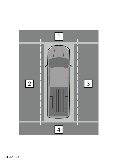

 360 Degree View Camera Alignment. General Procedures