Lincoln Nautilus: Power Steering / Power Steering - System Operation and Component Description. Description and Operation
System Operation
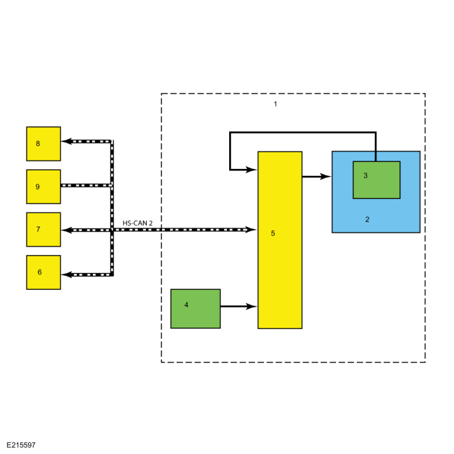
System Diagram

| Item | Description |
|---|---|
| 1 | EPAS gear |
| 2 | EPAS gear motor |
| 3 | EPAS gear motor position sensor |
| 4 | EPAS gear motor torque sensor |
| 5 | PSCM |
| 6 | ABS module |
| 7 | BCM |
| 8 | PAM |
| 9 | PCM |
Network Message Chart
Module Network Input Messages: Power Steering Control Module (PSCM)
| Broadcast Message | Originating Module | Message Purpose |
|---|---|---|
| ABS active | ABS | Used to confirm that the ABS is operational. |
| Power mode | BCM | Used to confirm the ignition status of the vehicle. |
| Stability control brake active | ABS | Used to confirm the operational state of the stability control system. |
| Traction control brake active | ABS | Used to confirm the operational state of the traction control system. |
| Transport mode | BCM | Used to confirm the vehicle is in normal operation mode, factory mode, transport mode or a crash event has been identified and the vehicle has been set to a post crash configuration. |
| Vehicle configuration/information | ABS | Used to compare the PSCM configuration against the vehicles specific configuration (central car configuration). |
| Vehicle speed | ABS | Used to determine the level of assist supplied. |
| Wheel speed data | ABS | Used to validate the steering wheel component angle by comparing the rotational speeds of each wheel. The difference in the speed of each wheel is used to derive a steering angle for comparison against the absolute steering angle message from the SASM . |
EPAS System
The PSCM controls the functions of the EPAS system and communicates with other modules over the HS-CAN2 .
To activate, the EPAS system needs to be connected to battery voltage at the hot at all times input and at the ignition/run input to the PSCM . In addition, the system must communicate with other modules over the HS-CAN2 . The PSCM must receive the power mode signal from the BCM in order to be set into operation mode.
The main input for calculating the level of EPAS assist is the steering torque sensor signal. Vehicle speed is also taken into consideration in order to achieve the vehicle speed dependent steering assist characteristic.
The EPAS gear uses a reversible motor to apply the steering assist. The motor is connected to the rack of the steering gear by a toothed belt and pulley/bearing assembly. The motor is used by the PSCM to move the rack inside the steering gear housing.
The PSCM continually monitors and adjusts steering efforts based on the steering torque sensor signal, motor position and HS-CAN2 inputs to enhance the feel of the steering system. As vehicle speed increases, the amount of assist decreases to improve and enhance road feel at the steering wheel. As vehicle speed decreases, the amount of assist increases to ease vehicle maneuvering. Compensation is made to reduce the effect of pull or drift that can be experienced when driving on roads with a high degree of camber. Also compensation for the impact of wheel imbalance on steering feel is made up to a predetermined threshold.
The steering torque sensor senses the torque at the steering wheel. It is integrated into the PSCM and works by measuring the relative rotation between an input and output shaft which are connected by a torsion bar. The steering torque sensor sends out 2 PWM signals which allows a channel to channel cross-check and an accurate correction of the neutral point.
The PSCM is self-monitoring and is capable of setting and storing Diagnostic Trouble Codes (DTCs). Depending on the DTC set, the PSCM may enter a failure mode. In addition, the PSCM may send a request to the IPC to display a message in the message center, alerting the driver of a potential EPAS concern. The warning message is sent over the HS-CAN2 to the BCM where it is converted to a MS-CAN message and forwarded on to the IPC over the MS-CAN .
Failure Modes
When a DTC is present in the PSCM , the EPAS enters 1 of 2 modes of operation.
The EPAS enters a reduced steering assist mode to protect the internal components of the EPAS when a concern is detected by the PSCM such as low/high battery voltage or over-temperature concerns that are not considered to be a critical safety concern. This reduced steering assist mode gives the steering a heavier than normal feel.
The EPAS enters a manual steering mode (no electrical steering assistance is provided) when a concern that is considered to be a critical safety concern is detected. In manual steering mode, the vehicle has mechanical steering operation only, which gives steering operation a heavy feel.
Active Park Assist
Some vehicles equipped with EPAS may also be equipped with active
park assist. The active park assist system is controlled by the PAM and,
when activated, can detect a parking space and steer the vehicle into
the space by sending commands to the EPAS
gear (the driver still controls the throttle, brakes and
transmission). The active park assist system is comprised of several
systems/modules that work together to aid in parallel parking maneuvers.
The presence of certain Diagnostic Trouble Codes (DTCs) in any of those
systems or modules may either keep the active park assist system from
being enabled or may disable the system if currently being used.
Refer to: Parking Aid (413-13C)
.
Component Description
EPAS Steering Gear
The EPAS gear is an assembly that consists of a PSCM , a motor, and a steering torque sensor, all of which are serviced as an assembly. The inner and outer tie rods and the gear bellows boots are available for service.
- The steering torque sensor is mounted near the input shaft of the EPAS gear and is used by the PSCM to determine how much force the steering wheel is being turned by.
- The EPAS gear has one inner tie rod located at each end of the gear assembly and is available separately for service.
- The EPAS gear has one outer tie rod located at each end of the gear assembly and is available separately for service.
- The EPAS gear has one bellows boot located at each side of the EPAS gear assembly. Each boot is held in place with 2 boot clamps. The boots and clamps are available for service.
PSCM
The PSCM is the ECU for the EPAS system. The module monitors all sensor inputs and HS-CAN2 messages that relate to the EPAS system and directly controls the output of the EPAS motor.

 Adaptive Steering. Diagnosis and Testing
VIN required to access Guided Routine (SECM)
..
Other information:
Lincoln Nautilus 2018-2026 Service Manual: Glass, Frames and Mechanisms. Diagnosis and Testing
DTC Chart: HVAC Module Diagnostics in this manual assume a certain skill level and knowledge of Ford-specific diagnostic practices. REFER to: Diagnostic Methods (100-00 General Information, Description and Operation). HVAC Module DTC Chart DTC Description Action B1C83:12 Rear Defog Relay: Circuit Short to Battery ..
Lincoln Nautilus 2018-2026 Service Manual: Azimuth System Check. General Procedures
Check NOTE: The object used in this system check can be fabricated using a 9 cm diameter (3 in I.D.) pipe, 100 cm (39 in) in length (available as Polyvinyl Chloride (PVC) pipe, or similar from a hardware or plumbing supply. NOTE: The following system check should be carried out with the vehicle on a level surface. NOTE: Actual sensor arrangement may differ from the configur..
Categories
- Manuals Home
- 1st Generation Nautilus Owners Manual
- 1st Generation Nautilus Service Manual
- Massage Seats
- Anti-Theft Alarm System Settings. Security – Troubleshooting
- Drive Mode Control
- New on site
- Most important about car
Changing a Flat Tire
WARNING: If the tire pressure monitor sensor becomes damaged it may not function.
Note: The use of tire sealant may damage your tire pressure monitoring system and should only be used in roadside emergencies. If you must use a sealant, use the Tire Mobility Kit sealant. Replace the tire pressure monitoring system sensor and valve stem on the wheel by an authorized dealer after use of the sealant.
Note: The tire pressure monitoring system indicator light will illuminate when the spare tire is in use. To restore the full function of the monitoring system, all road wheels equipped with tire pressure monitoring sensors must be mounted on the vehicle.
If you get a flat tire while driving, do not apply the brake hea