Lincoln Nautilus: Tire Pressure Monitoring System (TPMS) / Tire Pressure Monitoring System (TPMS) - System Operation and Component Description. Description and Operation
System Operation
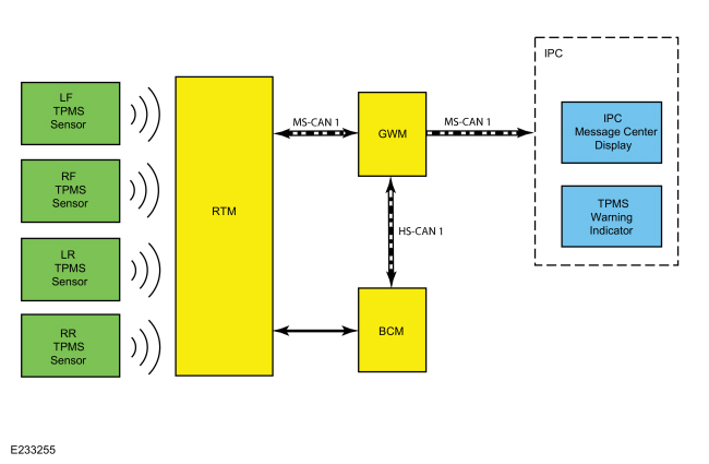
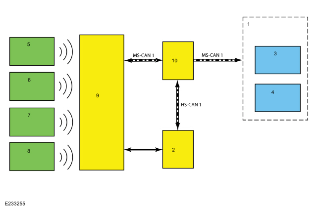
System Diagram
| Item | Description |
|---|---|
| 1 | IPC |
| 2 | BCM |
| 3 | IPC message center display |
| 4 | TPMS warning indicator |
| 5 | LH front TPMS sensor |
| 6 | RH front TPMS sensor |
| 7 | LH rear TPMS sensor |
| 8 | RH rear TPMS sensor |
| 9 | RTM |
| 10 | GWM |
Network Message Chart
BCM TPMS Network Input Messages
| Broadcast Message | Originating Module | Message Purpose |
|---|---|---|
| TPMS data | RTM | Communicates tire pressure information to the BCM |
TPMS Function
NOTE: When directed to train any TPMS sensors, use only the sensor training procedure outlined in this manual. Do not use the TPMS reset procedure outlined in the Owner's Literature as this procedure does not program new sensors to the module.
The TPMS uses 4 valve stem mounted sensors to monitor tire pressure. These sensors transmit tire pressure data to the RTM . Each individual sensor contains its own battery and transmits tire pressure data to the RTM . The RTM is a radio receiver which collects the tire pressure data and sends the information along the MS-CAN to the GWM which then sends the information to the BCM along the HS-CAN1 . All TPMS functions are controlled by the BCM . The TPMS sensors are trained (calibrated) to the BCM , which records the unique identifier for each sensor. The BCM records the location of each TPMS sensor based on the training (calibration) order and compares the tire pressure data sent by the sensors with a programmed tire pressure. This programmed pressure is specified on the VC label. If the tire pressure deviates from the programmed tire pressure the BCM , using the MS-CAN , signals the IPC to illuminate the TPMS warning indicator and display a message in the message center. The programmed tire pressure cannot be changed.
The diagnostic scan tool is useful in diagnosing TPMS concerns and may be used to verify the accuracy of the tire pressure data transmitted by the TPMS sensors. This is accomplished by comparing the BCM tire pressure PID data to the actual tire pressure using a digital tire pressure gauge.
It is not necessary to train the sensors after a tire rotation on vehicles with the same front and rear tire pressures however, the BCM cannot recognize the sensor identifiers have been moved to different positions and retains the original position information for each sensor.
Wheel Rotation and Sensor Training Techniques
Training known good sensors from another vehicle can help determine whether the concern is with a sensor or the RTM . This technique cannot help determine whether the concern is due to RFI as some RFI source could be preventing the RTM from receiving the tire pressure status from the known good sensors as well as the original sensors.
If the RTM in the suspect vehicle cannot train any of the original sensors and, likewise, cannot train known good sensors from another vehicle, then the concern is with the module or RFI and not with the original sensors. The original sensors should not be replaced. If a sensor in a certain location has caused several events, yet the sensor trains and seems to operate normally, moving that particular wheel to a different location on the vehicle is a good way to isolate the concern to a certain sensor/wheel location. Rotate the wheels and road test the vehicle. This can be done in an attempt to replicate the concern and help determine if the concern followed the sensor or remained in the original sensor location.
If
the vehicle has been stationary for more than 30 minutes, the sensors
go into a "sleep mode" to conserve battery power and need to be "woken
up" so they transmit the latest tire pressure information to the RTM .
Refer
to: Tire Pressure Monitoring System (TPMS) Sensor Activation (204-04B
Tire Pressure Monitoring System (TPMS), General Procedures).
Training Sensors in a Different Order
If the first sensor fails the TPMS training procedure, the BCM aborts the entire procedure. Starting the training procedure at a different wheel is a technique that can be used to determine if the remaining sensors can train to the module. This can help save time determining if one sensor is damaged, other sensors are having concerns or the BCM is experiencing training difficulties with a certain TPMS sensor location.
TPMS Warning Indicator
The TPMS warning indicator is used to indicate both a low tire pressure event and a possible system fault condition. The message center displays additional information associated with the low tire pressure event or the system fault condition. Occasionally, the warning indicator and message center indicate faults that cannot be resolved by the customer. Treat these as TPMS faults that must be serviced.
TPMS Warning Indicator Illuminates Continuously
The TPMS warning indicator remains on continuously and the message center displays LOW TIRE PRESSURE when any of the tire pressures fall below the low pressure limit. When this condition exists, adjust the tire pressure to the recommended cold tire pressure indicated on the VC label.
Tire Pressure Monitoring System (TPMS) Warning Indicator Flashes
The TPMS warning indicator flashes for 70 seconds and then remains on continuously when the ignition is set to ON and the TPMS is malfunctioning. The TPMS status (TPMS_STATUS) PID can be used to determine why the TPMS warning indicator is flashing.
- Tire Pressure Sensor Fault — The message center displays TIRE PRESSURE SENSOR FAULT when a TPMS sensor is malfunctioning.
- No communication with the BCM — The TPMS warning indicator illuminates when the IPC has not received any signals from the BCM for more than 5 seconds. The message center displays TIRE PRESSURE MONITOR FAULT.
- Tire Pressure Monitor Fault — The message center displays TIRE PRESSURE MONITOR FAULT when the TPMS is malfunctioning.
TPMS PID Definitions
The BCM monitors the TPMS status. Use the diagnostic scan tool to view the current status of the TPMS status (TPMS_STATUS) PID . This helps identify the current system status and may aid in diagnosing the system. The PID has 4 valid states:
- TPMS_STATUS PID displays SENSOR FAULT if the BCM has not received the tire pressure data from 1 to 3 TPMS sensors for 20 minutes when vehicle speed is above 32.2 km/h (20 mph).
- TPMS_STATUS PID displays SYSTEM FAULT if the BCM has not received the tire pressure data from all 4 TPMS sensors for 20 minutes when vehicle speed is above 32.2 km/h (20 mph).
- TPMS_STATUS PID displays LOW if the BCM has detected that at least 1 TPMS sensor is reporting low tire pressure.
- TPMS_STATUS PID displays SYSTEM ACTIVE if the TPMS is functioning normally.
Last Warning Event PID Definitions
The TPMS uses the TPMS last warning event Parameter Identifications (PIDs) to store detailed information about the last 5 times the TPMS warning indicator was activated. These Parameter Identifications (PIDs) can be used to acquire more information about a particular TPMS event, but must be used carefully.
| PID | Definition |
|---|---|
| EVT1_AGE_IGN through EVT5_AGE_IGN | The number of key cycles since the TPMS was activated. This PID cycles from zero to 255 and then starts over from zero again. This can be used to determine how long ago a TPMS event occurred and the time (in key cycles) between events. |
| EVT1_TR_LOC through EVT5_TR_LOC | This is the last programmed location for the TPMS sensor identifier causing each TPMS event. Due to tire rotation, the sensor may no longer be at the original location. It is suggested that all the Parameter Identifications (PIDs) be recorded, the system retrained, and then the sensor identifier Parameter Identifications (PIDs) be used to pinpoint the actual location of each sensor. |
| EVT1_PRES_BP through EVT5_PRES_BP | This is the tire pressure associated with each TPMS indicator event. This can be used along with the function code to clearly identify the TPMS events that were strictly due to low pressure. It can also be used to determine when a sensor is transmitting inaccurate tire pressure. |
| EVT1_SNSR_ST through EVT5_SNSR_ST |
|
| EVT1_SNSR_ID through EVT5_SNSR_ID | This is the identifier of the sensor involved in each TPMS event. EVT1 is the most recent event that triggered the TPMS warning indicator. |
Radio Frequency Interference (RFI)
RFI can be caused by:
- Video equipment has been found to cause RFI especially when the video and power supply lines are near the TPMS .
- Anti-theft alarms (even those installed by the dealership) have been found to create enough RFI to cause the TPMS to malfunction or lose considerable range. These anti-theft alarms can be difficult to locate, as they are usually hidden somewhere out of the way for reduced accessibility.
- Many in-vehicle cell phone chargers have been found to cause considerable RFI . The vehicles with the power point closest to the RTM are the most affected. It must be noted that most cell phone chargers do not produce high levels of RFI all the time. This depends on the state of charge of the cell phone battery. The phone battery must be almost completely discharged in some cases.
- Power supplies and DC / AC inverters typically create a lot of RFI . Most consumer grade equipment has very little filtering or shielding.
Using Hit Rate Parameter Identifiers (PIDs) to Determine the Presence of RFI
If an intermittent RFI issue is suspected, the information contained in the last 5 TPMS warning event Parameter Identifiers (PIDs) can be combined with specific Parameter Identifiers (PIDs) from the BCM to determine which TPMS sensors are being affected and if a RFI source is currently present in the vehicle.
The BCM module contains Parameter Identifiers (PIDs) used to keep track of the number of TPMS messages received from the 4 trained TPMS sensors. These Parameter Identifiers (PIDs) can provide insight on the performance of the TPMS , and can help establish the presence of an Frequency Interference (RFI) source.
- TPM_HITS_LF (Tire Pressure Monitor Hit Rate Left Front) – The number of TPMS messages received by the BCM module from the LH front sensor
- TPM_HITS_RF (Tire Pressure Monitor Hit Rate Right Front) – The number of TPMS messages received by the BCM module from the RH front sensor.
- TPM_HITS_LRO (Tire Pressure Monitor Hit Rate Left Rear Outer) – The number of TPMS messages received by the BCM module from the LH rear sensor
- TPM_HITS_RRO (Tire Pressure Monitor Hit Rate Right Rear Outer) – The number of TPMS messages received by the BCM module from the RH rear sensor.
Method for determining if a RFI issue has been affecting the TPMS :
- Collect the last 5 TPMS events and determine if they were due to system faults or low tire air pressure.
- Collect the TPMS Hit Rate PID counters and compare them to the last 5 TPMS events.
- If the TPMS Hit Rate PID counters are significantly different from each other or if the locations with lower hit rate values show up as fault locations in last 5 TPMS events and BCM DTC B124D:02 (Tire Pressure Sensor: General Signal Failure) is present, an intermittent RFI source is most likely preventing the signals from these TPMS sensors from reaching the BCM .
- An intermittent RFI source can also be the case when all 4 TPMS sensors show up in the last 5 fault events and BCM DTC B1182:00 (Tire Pressure Monitoring System (TPMS): No Sub Type Information) is present. The possible cause would a strong source of RFI noise.
Original Equipment Manufacturer (OEM) Modules
In some cases the RFI may actually be caused by a module or ground on the vehicle. Depending on the severity of the concern, a dirty ground, improperly built ground shield or module can disable the system. Modules that have microcontrollers using clock circuits to create timing pulses for the microprocessor may radiate RFI .
Using Customer Electronics to Pinpoint RFI
This method can be a way to determine the cause of a concern before the sensors and module are replaced with little or no effect on system performance. Discuss with the customer what types of devices they were using when the event occurred. Determine which power points are being used and, if necessary, ask the devices be activated to determine their affect on the TPMS .
Options for Eliminating Intermittent TPMS Operation Caused by RFI
- If an Original Equipment Manufacturer (OEM) component or customer device is causing a RFI concern, replace the device.
- If a phone charger is causing a RFI concern, the customer should consult with their cell phone provider to acquire a different battery charger.
- If a device such as a dealer installed anti-theft alarm is causing a RFI concern, move the device to another location in the vehicle. In the case of a portable device move the power cord to another power point location.
In summary, if the RFI source is present and cannot be moved or replaced, the intermittent concern remains. The TPMS must accept the unwanted system operation the RFI can cause.
Ambient Temperature Change and Tire Pressure
Tire pressures fluctuate with temperature changes. For this reason, tire pressures must be set to specification when tires are at outdoor ambient temperatures. If the vehicle is allowed to warm up to shop temperatures, and the outside temperature is less than shop temperature, the tire inflation pressure must be adjusted accordingly.
If the tires are inflated to specification at shop temperatures, and the vehicle is moved outdoors when the outdoor ambient temperature is significantly lower, the tire pressure may drop enough to be detected by the TPMS and illuminate the TPMS warning indicator.
As the ambient temperature decreases by -12.2° C (10° F), tire pressure decreases 6.9 kPa (1 psi). Adjust the tire pressure by 6.9 kPa (1 psi) for each -12.2° C (10° F) of ambient temperature drop as necessary to keep the tire at the specified VC label pressure. To adjust the tire pressure indoors for colder outside temperatures, refer to the following table.
NOTE: Table is based on a garage temperature of 21°C (70°F). Max Pressure Adjustment is 50 kPa (7 psi).
| Tire Placard Pressure | |||||
| 29.7 psi ( 205 kPa) | 31.9 psi ( 220 kPa) | 34.1 psi ( 235 kPa) | 34.8 psi ( 240 kPa) | 37.7 psi ( 260 kPa) | |
| Outside Temperature | Tire Target Pressure | ||||
| 69.8 °F ( 21 °C) | 29.7 psi ( 205 kPa) | 31.9 psi ( 220 kPa) | 34.1 psi ( 235 kPa) | 34.8 psi ( 240 kPa) | 37.7 psi ( 260 kPa) |
| 60.8 °F ( 16 °C) | 31.2 psi ( 215 kPa) | 33.4 psi ( 230 kPa) | 34.8 psi ( 240 kPa) | 36.3 psi ( 250 kPa) | 39.2 psi ( 270 kPa) |
| 50.0 °F ( 10 °C) | 31.9 psi ( 220 kPa) | 34.1 psi ( 235 kPa) | 36.3 psi ( 250 kPa) | 37.0 psi ( 255 kPa) | 42.1 psi ( 290 kPa) |
| 39.2 °F ( 4 °C) | 33.4 psi ( 230 kPa) | 34.8 psi ( 240 kPa) | 37.0 psi ( 255 kPa) | 37.7 psi ( 260 kPa) | 42.8 psi ( 295 kPa) |
| 30.2 °F ( -1 °C) | 34.1 psi ( 235 kPa) | 36.3 psi ( 250 kPa) | 37.7 psi ( 260 kPa) | 39.2 psi ( 270 kPa) | 44.2 psi ( 305 kPa) |
Component Description
BCM
The BCM is a multifunction module that monitors all sensor inputs and all CAN messages that relate to the TPMS . The BCM records and retains the unique sensor identifier of each TPMS sensor.
The BCM retains the previous sensor location information following a
tire rotation. For the BCM to learn the new sensor location, the
sensors must be trained (calibrated) to the BCM .
Refer to: Tire
Pressure Monitoring System (TPMS) Sensor Location Calibration (204-04B
Tire Pressure Monitoring System (TPMS), General Procedures).
Additionally, the sensors must be trained when a new BCM is installed.
When installing a new BCM
, there are several procedures that must be carried out in order for
the module to function correctly. These procedures include, but are not
limited to; PMI , anti-theft parameter reset, programming keyless entry remote and setting customer preferences.
Refer to: Body Control Module (BCM) (419-10 Multifunction Electronic Modules, Removal and Installation).
Additionally, the sensors must be trained when a new BCM is installed. TPMS pressure data is cleared from the BCM when the module is flashed or reconfigured. When the data is cleared, the tire pressure DID's reset to the factory default of 1033 kPa (149.96 psi) and the IPC displays dashes for the tire pressures. The sensors must be activated to transmit the latest tire pressure information.
RTM
The RTM is a radio receiver used to collect the tire pressure data from the TPMS sensors.
TPMS Sensor
Each of the 4 TPMS sensors contain a battery, a tire pressure sensor and a radio transmitter. The TPMS sensor radio transmissions are sent approximately once every 60 seconds when the vehicle speed exceeds 32.2 km/h (20 mph).
 Tire Pressure Monitoring System (TPMS) - Overview. Description and Operation
Overview
The BCM uses tire pressure sensors to monitor tire pressure. The
sensors use radio signals to transmit the tire pressure to the RTM . The
RTM sends the information to the BCM over the Medium Speed Controller
Area Network (MS-CAN) and K-Line...
 Tire Pressure Monitoring System (TPMS). Diagnosis and Testing
DTC Charts
Diagnostics in this manual assume a certain skill level and knowledge of Ford-specific diagnostic practices. REFER to: Diagnostic Methods (100-00 General Information, Description and Operation)...
Other information:
Lincoln Nautilus 2018-2025 Service Manual: Power Fold Seat Control Switch. Removal and Installation
Special Tool(s) / General Equipment Interior Trim Remover Removal On both sides. Using an interior trim tool, release the power fold seat control switch locking tabs. Use the General Equipment: Interior Trim Remover Disconnect the electrical connector and remove the power fold seat control switch...
Lincoln Nautilus 2018-2025 Owners Manual: Wipers and Washers – Troubleshooting
Wipers and Washers – Warning Lamps Illuminates when the windshield washer fluid is low. Wipers and Washers – Frequently Asked Questions Why are there streaks and smears on the windshield? The wiper blades could be dirty, worn or damaged. Check the wiper blades...
Categories
- Manuals Home
- 1st Generation Nautilus Owners Manual
- 1st Generation Nautilus Service Manual
- Folding the Exterior Mirrors - Vehicles With: Manual Folding Mirrors. Folding the Exterior Mirrors - Vehicles With: Power Folding Mirrors
- Opening the Liftgate
- Interior Lamp Function. Adjusting the Instrument Panel Lighting Brightness. Ambient Lighting. Interior Lighting – Troubleshooting
- New on site
- Most important about car
Locating the Pre-Collision Assist Sensors

If a message regarding a blocked sensor or camera appears in the information display, something is obstructing the radar signals or camera images. The radar sensor is behind the fascia cover in the center of the lower grille. With a blocked sensor or camera, the system may not function, or performance may reduce. See Pre-Collision Assist – Information Messages.