Lincoln Nautilus: Rear End Sheet Metal Repairs / Water Drain Panel Reinforcement. Removal and Installation
Special Tool(s) / General Equipment
| Resistance Spotwelding Equipment | |
| 8 mm Drill Bit | |
| MIG/MAG Welding Equipment | |
| Spot Weld Drill Bit | |
| Locking Pliers |
Materials
| Name | Specification |
|---|---|
| Seam Sealer TA-2-B, 3M™ 08308, LORD Fusor® 803DTM |
- |
Removal
NOTE: Left hand (LH) side shown, right hand (RH) side similar.
NOTE: Factory welds may be substituted with resistance or metal inert gas (MIG) plug welds. Resistance welds may not be placed directly over original location. They must be placed adjacent to original location and match factory welds in quantity. Metal inert gas (MIG) plug welds must equal factory welds in both location and quantity.
NOTE: Adequately protect all adjacent areas against cutting, grinding and welding procedures.
-
Depower the SRS .
Refer to: Supplemental Restraint System (SRS) Depowering (501-20B Supplemental Restraint System, General Procedures).
-
If Required:
Dimensionally restore the vehicle to pre-damage condition.
Refer to: Body and Frame (501-26 Body Repairs - Vehicle Specific Information and Tolerance Checks, Description and Operation).
-
Remove the water drain panel.
Refer to: Water Drain Panel (501-30 Rear End Sheet Metal Repairs, Removal and Installation).
-
Position the carpeting and the wiring harness away from the working area.
-
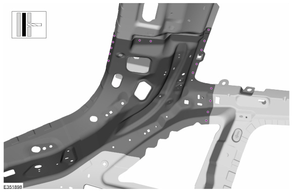
Remove the spot welds.
Use the General Equipment: Spot Weld Drill Bit
.jpg) |
-
Remove the spot welds.
Use the General Equipment: Spot Weld Drill Bit
 |
-
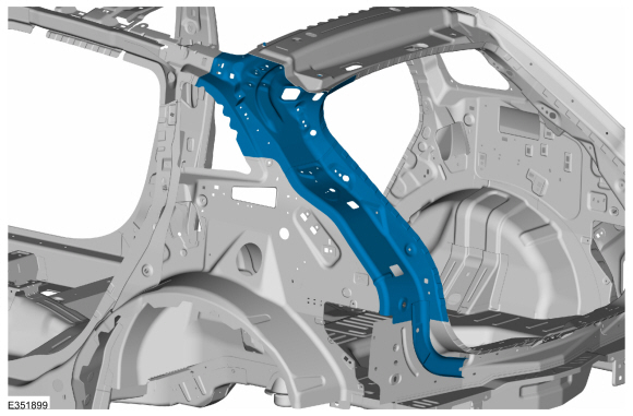
Remove the water drain panel reinforcement.
 |
Installation
NOTE: Factory welds may be substituted with resistance or metal inert gas (MIG) plug welds. Resistance welds may not be placed directly over original location. They must be placed adjacent to original location and match factory welds in quantity. Metal inert gas (MIG) plug welds must equal factory welds in both location and quantity.
NOTE: Left hand (LH) side shown, right hand (RH) side similar.
NOTE: Adequately protect all adjacent areas against cutting, grinding and welding procedures.
-
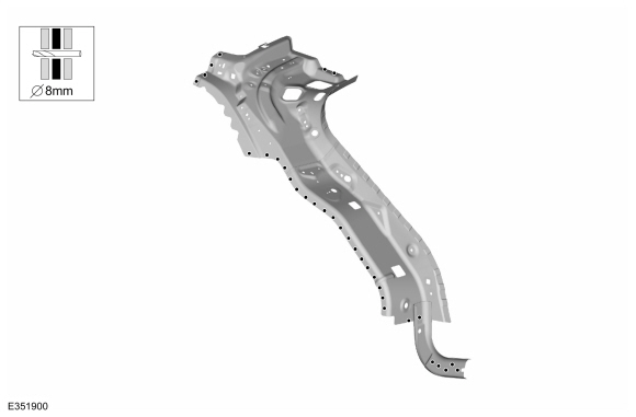
Drill plug weld holes in the water drain panel reinforcement.
Use the General Equipment: 8 mm Drill Bit
 |
-
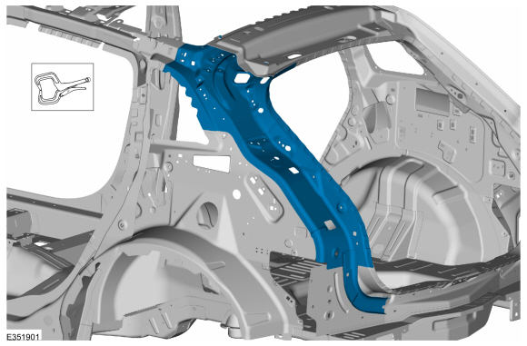
Install,properly position and clamp the water drain panel reinforcement.
Use the General Equipment: Locking Pliers
 |
-
Install the welds.
Use the General Equipment: MIG/MAG Welding Equipment
Use the General Equipment: Resistance Spotwelding Equipment
 |
-
Install the welds.
Use the General Equipment: MIG/MAG Welding Equipment
Use the General Equipment: Resistance Spotwelding Equipment
 |
-
Dress all welds as required using typical metal finishing techniques.
-
Sealing work:
All areas must be sealed to production level.
Material: Seam Sealer / TA-2-B, 3M™ 08308, LORD Fusor® 803DTM
-
Refinish the repair using a Ford approved paint system.
-
Restore corrosion protection.
Refer to: Corrosion Prevention (501-25 Body Repairs - General Information, General Procedures).
-
Reposition the carpeting and the wiring harness to original location.
-
Install the water drain panel.
Refer to: Water Drain Panel (501-30 Rear End Sheet Metal Repairs, Removal and Installation).
-
Repower the SRS .
Refer to: Supplemental Restraint System (SRS) Repowering (501-20B Supplemental Restraint System, General Procedures).
 Water Drain Panel. Removal and Installation
Special Tool(s) /
General Equipment
Resistance Spotwelding Equipment
8 mm Drill Bit
MIG/MAG Welding Equipment
Spot Weld Drill Bit
Locking Pliers
Materials
Name
Specification
Seam SealerTA-2-B, 3M™ 08308, LORD Fusor® 803DTM
-
Removal
NOTE:
Left hand (LH) side shown, right hand (RH) side similar...

Other information:
Lincoln Nautilus 2018-2026 Owners Manual: Maintenance Precautions
Service your vehicle regularly to help maintain its roadworthiness and resale value. There is a large network of authorized dealers that are there to help you with their professional servicing expertise. We believe that their specially trained technicians are best qualified to service your vehicle properly and expertly. They are supported by a wide range of highly specialized tools develop..
Lincoln Nautilus 2018-2026 Owners Manual: What Is the Garage Door Opener. How Does the Garage Door Opener Work. Garage Door Opener Precautions
What Is the Garage Door Opener HomeLink Wireless Control System The universal garage door opener replaces the common hand-held garage door opener with a three-button transmitter integrated into the driver’s sun visor. How Does the Garage Door Opener Work The system includes two primary features, a garage door opener and a platform for remote activation of devices within the home. You can ..
Categories
- Manuals Home
- 1st Generation Nautilus Owners Manual
- 1st Generation Nautilus Service Manual
- Auto Hold
- Changing the 12V Battery
- Power Outlet - Vehicles With: 110V Power Outlet
- New on site
- Most important about car
Changing a Flat Tire
WARNING: If the tire pressure monitor sensor becomes damaged it may not function.
Note: The use of tire sealant may damage your tire pressure monitoring system and should only be used in roadside emergencies. If you must use a sealant, use the Tire Mobility Kit sealant. Replace the tire pressure monitoring system sensor and valve stem on the wheel by an authorized dealer after use of the sealant.
Note: The tire pressure monitoring system indicator light will illuminate when the spare tire is in use. To restore the full function of the monitoring system, all road wheels equipped with tire pressure monitoring sensors must be mounted on the vehicle.
If you get a flat tire while driving, do not apply the brake hea