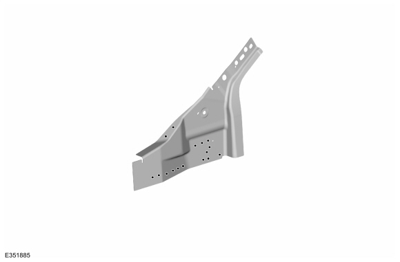
Lincoln Nautilus: Side Panel Sheet Metal Repairs / A-Pillar Reinforcement. Removal and Installation
Special Tool(s) / General Equipment
| Hot Air Gun | |
| 8 mm Drill Bit | |
| MIG/MAG Welding Equipment | |
| Spot Weld Drill Bit | |
| Locking Pliers |
Materials
| Name | Specification |
|---|---|
| Metal Bonding Adhesive TA-1, TA-1-B, 3M™ 08115, LORD Fusor® 108B, Henkel Teroson EP 5055 |
- |
| Seam Sealer TA-2-B, 3M™ 08308, LORD Fusor® 803DTM |
- |
Removal
NOTE: Left hand (LH) side shown, right hand (RH) side similar.
NOTE: Factory welds may be substituted with resistance or metal inert gas (MIG) plug welds. Resistance welds may not be placed directly over original location. They must be placed adjacent to original location and match factory welds in quantity. Metal inert gas (MIG) plug welds must equal factory welds in both location and quantity.
NOTE: Adequately protect all adjacent areas against cutting, grinding and welding procedures.
-
Depower the SRS .
Refer to: Supplemental Restraint System (SRS) Depowering (501-20B Supplemental Restraint System, General Procedures).
-
If Required:
Dimensionally restore the vehicle to pre-damage condition.
Refer to: Body and Frame (501-26 Body Repairs - Vehicle Specific Information and Tolerance Checks, Description and Operation).
-
Remove the instrument panel.
Refer to: Instrument Panel (501-12 Instrument Panel and Console, Removal and Installation).
-
Remove the roof side rail.
Refer to: Roof Side Rail (501-28 Roof Sheet Metal Repairs, Removal and Installation).
-
Position the wiring harnesses away from the working area.
-
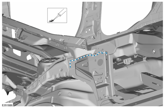
Remove the welds.
Use the General Equipment: Spot Weld Drill Bit
.jpg) |
-
NOTE: Pay particular attention to the location of adhesives and sealers to aid in installation.
Break the adhesive bond and remove the A-pillar reinforcement.
Use the General Equipment: Hot Air Gun
.jpg) |
Installation
NOTE: Left hand (LH) side shown, right hand (RH) side similar.
NOTE: Factory welds may be substituted with resistance or metal inert gas (MIG) plug welds. Resistance welds may not be placed directly over original location. They must be placed adjacent to original location and match factory welds in quantity. Metal inert gas (MIG) plug welds must equal factory welds in both location and quantity.
NOTE: Adequately protect all adjacent areas against cutting, grinding and welding procedures.
-
Drill plug weld holes in the replacement A-pillar reinforcement.
Use the General Equipment: 8 mm Drill Bit
 |
-
Apply adhesive as indicated.
Material: Metal Bonding Adhesive / TA-1, TA-1-B, 3M™ 08115, LORD Fusor® 108B, Henkel Teroson EP 5055
 |
-
Install, properly position ,clamp and weld the A-pillar reinforcement.
Use the General Equipment: Locking Pliers
Use the General Equipment: MIG/MAG Welding Equipment
.jpg) |
-
Dress all welds as required using typical metal finishing techniques and materials.
-
Sealing work:
All areas must be sealed to production level.
Material: Seam Sealer / TA-2-B, 3M™ 08308, LORD Fusor® 803DTM
-
Refinish the entire repair using a Ford approved paint system.
-
Restore corrosion protection.
Refer to: Corrosion Prevention (501-25 Body Repairs - General Information, General Procedures).
-
Reposition the wiring harnesses to original location.
-
Install the roof side rail.
Refer to: Roof Side Rail (501-28 Roof Sheet Metal Repairs, Removal and Installation).
-
Install the instrument panel.
Refer to: Instrument Panel (501-12 Instrument Panel and Console, Removal and Installation).
-
Repower the SRS .
Refer to: Supplemental Restraint System (SRS) Repowering (501-20B Supplemental Restraint System, General Procedures).

 B-Pillar and Reinforcement. Removal and Installation
Special Tool(s) /
General Equipment
Resistance Spotwelding Equipment
Spherical Cutter
Hot Air Gun
Air Body Saw
8 mm Drill Bit
MIG/MAG Welding Equipment
Spot Weld Drill Bit
Locking Pliers
Materials
Name
Specification
Metal Bonding AdhesiveTA-1, TA-1-B, 3M™ 08115, LORD Fusor® 108B, Henkel Teroson EP 5055
-
Seam SealerTA-2-B, 3M™..
Other information:
Lincoln Nautilus 2018-2026 Owners Manual: Folding the Exterior Mirrors - Vehicles With: Manual Folding Mirrors. Folding the Exterior Mirrors - Vehicles With: Power Folding Mirrors
Folding the Exterior Mirrors - Vehicles With: Manual Folding Mirrors Push the mirror toward the door window glass. Make sure that you fully engage the mirror in its support when returning it to its original position. Folding the Exterior Mirrors - Vehicles With: Power Folding Mirrors With the auto-fold feature enabled, the exterior mirrors fold in toward the glass after you place the transmis..
Lincoln Nautilus 2018-2026 Service Manual: Air Distribution Door Actuator. Removal and Installation
Removal Refer to: Passenger Knee Airbag (501-20B Supplemental Restraint System, Removal and Installation). Remove the screws and the air distribution door actuator. Disconnect the electrical connector. Installation To install, reverse the removal procedure. ..
Categories
- Manuals Home
- 1st Generation Nautilus Owners Manual
- 1st Generation Nautilus Service Manual
- Child Safety Locks
- Massage Seats
- Normal Scheduled Maintenance
- New on site
- Most important about car
Locating the Pre-Collision Assist Sensors

If a message regarding a blocked sensor or camera appears in the information display, something is obstructing the radar signals or camera images. The radar sensor is behind the fascia cover in the center of the lower grille. With a blocked sensor or camera, the system may not function, or performance may reduce. See Pre-Collision Assist – Information Messages.