Lincoln Nautilus: Hydraulic Brake Actuation / Brake Master Cylinder. Removal and Installation
Removal
NOTICE: Do not spill brake fluid on painted or plastic surfaces or damage to the surface may occur. If brake fluid is spilled onto a painted or plastic surface, immediately wash the surface with water.
NOTE: Removal steps in this procedure may contain installation details.
-
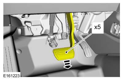
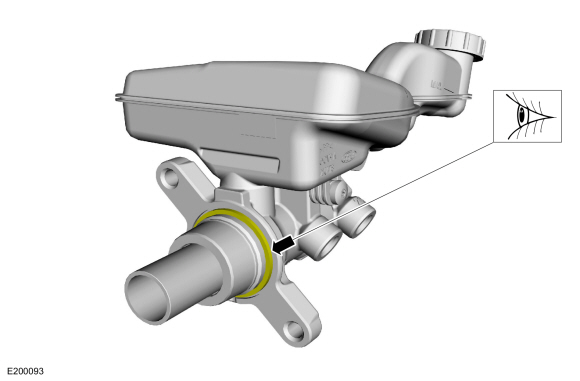
NOTICE: Before removing the master cylinder, relieve the vacuum in the brake booster or the master cylinder O-ring seal may be drawn into the brake booster, causing brake booster failure and increased brake pedal effort.
Fully apply and release the brake pedal 5 times.
 |
-
Remove the battery.
Refer to: Battery (414-01 Battery, Mounting and Cables, Removal and Installation).
-
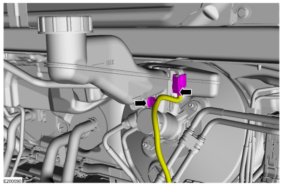
Disconnect the brake fluid level sensor electrical connector and detach the wiring retainer.
 |
-
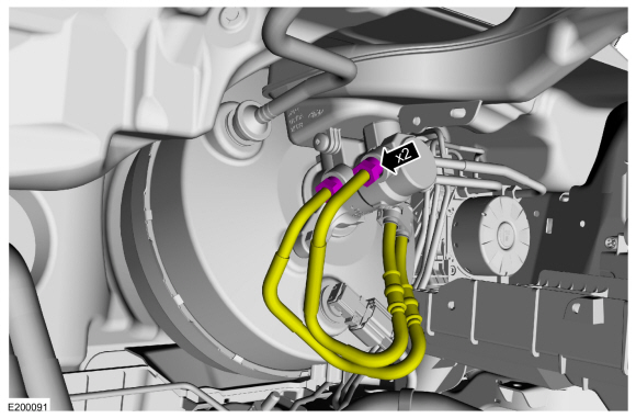
Disconnect the brake tube fittings.
Torque: 20 lb.ft (27.5 Nm)
 |
-
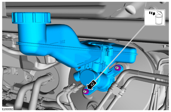
Remove the nuts and the brake master cylinder. Discard the nuts.
Torque: 20 lb.ft (27.6 Nm)
 |
-
Make sure that the master cylinder-to-booster seal is removed with the master cylinder.
 |
Installation
-
To install, reverse the removal procedure.
-
-
If a new brake master cylinder has been installed, bleed the master cylinder.
Refer to: Component Bleeding (206-00 Brake System - General Information, General Procedures).
-
If the brake master cylinder was removed to access other components, bleed the brake system.
Refer to: Brake System Pressure Bleeding (206-00 Brake System - General Information, General Procedures).
-
If a new brake master cylinder has been installed, bleed the master cylinder.
 Brake Fluid Reservoir. Removal and Installation
Materials
Name
Specification
Motorcraft® DOT 4 LV High Performance Motor Vehicle Brake FluidPM-20
WSS-M6C65-A2
Removal
NOTICE:
Do not spill brake fluid on painted or plastic surfaces or
damage to the surface may occur...
 Brake Pedal and Bracket. Removal and Installation
Removal
NOTE:
Removal steps in this procedure may contain installation details.
Remove the nuts, disconnect the electrical connector and remove the LH insulator panel...
Other information:
Lincoln Nautilus 2018-2026 Service Manual: Direct Current/Alternating Current (DC/AC) Inverter. Diagnosis and Testing
Inspection and Verification Before diagnosing or repairing the Direct Current/Alternating Current (DC/AC) Inverter system refer to the Owner's Literature and REFER to: Direct Current/Alternating Current (DC/AC) Inverter - System Operation and Component Description (414-05 Voltage Converter/Inverter, Description and Operation)...
Lincoln Nautilus 2018-2026 Service Manual: Powertrain/Drivetrain Mount Neutralizing. General Procedures
Adjustment NOTE: Refer to the appropriate section and procedure for special instructions on loosening and tightening mount fasteners. Refer to: Jacking and Lifting - Overview (100-02 Jacking and Lifting, Description and Operation). Loosen, but do not remove, the powertrain/drivetrain mount fasteners...
Categories
- Manuals Home
- 1st Generation Nautilus Owners Manual
- 1st Generation Nautilus Service Manual
- Anti-Theft Alarm System Settings. Security – Troubleshooting
- USB Ports
- Fuel Quality
- New on site
- Most important about car
Locating the Pre-Collision Assist Sensors

If a message regarding a blocked sensor or camera appears in the information display, something is obstructing the radar signals or camera images. The radar sensor is behind the fascia cover in the center of the lower grille. With a blocked sensor or camera, the system may not function, or performance may reduce. See Pre-Collision Assist – Information Messages.