Lincoln Nautilus: Hydraulic Brake Actuation / Brake Pedal and Bracket. Removal and Installation
Removal
NOTE: Removal steps in this procedure may contain installation details.
-
Remove the nuts, disconnect the electrical connector and remove the LH insulator panel.
 |
-
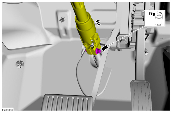
NOTICE: Do not service the brake pedal or brake booster without first removing the stoplamp switch. This switch must be removed with the brake pedal in the at-rest position. The switch plunger must be compressed for the switch to rotate in the bracket. Attempting to remove the switch when the plunger is extended (during pedal apply) will result in damage to the switch.
Remove the stoplamp switch. Refer to: Stoplamp Switch (417-01 Exterior Lighting, Removal and Installation).
-
Remove the accelerator pedal.
Refer to: Accelerator Pedal (310-02 Acceleration Control, Removal and Installation).
-
Remove the screws and the lower steering column shroud.
 |
-
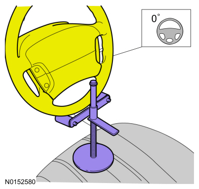
NOTICE: Do not allow the steering column shaft to rotate while disconnected from the gear or damage to the clockspring may occur. If there is evidence that the steering column shaft has rotated, remove and recenter the clockspring. Refer to Section 501-20B.
Secure the steering wheel using a steering wheel holding device.
 |
-
Remove and discard the steering column shaft bolt. WARNING:
Do not reuse steering column shaft bolts. This may
result in fastener failure and steering column shaft detachment or loss
of steering control. Failure to follow this instruction may result in
serious injury to vehicle occupant(s).
WARNING:
Do not reuse steering column shaft bolts. This may
result in fastener failure and steering column shaft detachment or loss
of steering control. Failure to follow this instruction may result in
serious injury to vehicle occupant(s).
Torque: 18 lb.ft (25 Nm)
 |
-
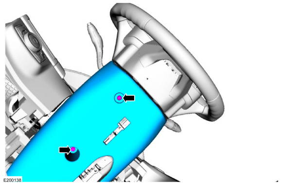
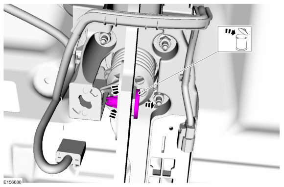
Compress the tabs and remove the clevis pin. Discard the pin.
 |
-
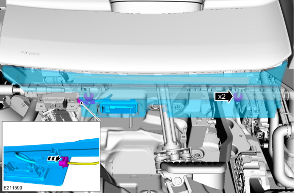
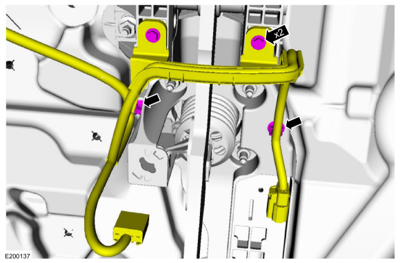
Remove the screws, detach the wiring retainers and position the wiring aside.
 |
-
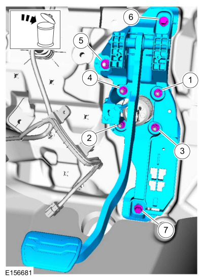
Remove the nut, bolts and the brake pedal and bracket. Discard the nuts and bolts.
Torque: 17 lb.ft (23 Nm)
 |
Installation
-
NOTICE: Do not press, pull or otherwise move the brake pedal while installing the stoplamp switch. The switch must be installed with the booster push rod attached to the brake pedal and with the brake pedal in the at-rest position. Installing the switch with the brake pedal in any other position will result in incorrect adjustment and may damage the switch.
To install, reverse the removal procedure.
 Brake Master Cylinder. Removal and Installation
Removal
NOTICE:
Do not spill brake fluid on painted or plastic surfaces or
damage to the surface may occur. If brake fluid is spilled onto a
painted or plastic surface, immediately wash the surface with water...

Other information:
Lincoln Nautilus 2018-2026 Service Manual: Front Door Tweeter Speaker. Removal and Installation
Removal All vehicles Remove the front door trim panel. Refer to: Front Door Trim Panel (501-05 Interior Trim and Ornamentation, Removal and Installation). Vehicles with: Harman Revel Audio System Remove the screws and the tweeter speaker through the front of the door panel. Vehicles with: AM/FM/CD/SYNC/Touchscreen Display Remove th..
Lincoln Nautilus 2018-2026 Owners Manual: Starting and Stopping the Engine – Troubleshooting
Starting and Stopping the Engine – Warning Lamps Malfunction Indicator Lamp If it illuminates when the engine is running, the on-board diagnostics system is detecting a malfunction of the vehicle emission control system. If it flashes, engine misfire could be occurring. Increased exhaust gas temperatures could damage the catalytic converter or other vehicle components. Avoid heavy accel..
Categories
- Manuals Home
- 1st Generation Nautilus Owners Manual
- 1st Generation Nautilus Service Manual
- Engine Oil Capacity and Specification - 2.0L
- Opening the Liftgate
- Switching the Lane Keeping System On and Off. Switching the Lane Keeping System Mode
- New on site
- Most important about car
Clearing the Garage Door Opener. Reprogramming the Garage Door Opener. Garage Door Opener Radio Frequencies
Clearing the Garage Door Opener