
Lincoln Nautilus: Supplemental Restraint System / C-Pillar Side Impact Sensor. Removal and Installation
Removal
 WARNING:
The following procedure prescribes critical repair steps
required for correct restraint system operation during a crash. Follow
all notes and steps carefully. Failure to follow step instructions may
result in incorrect operation of the restraint system and increases the
risk of serious personal injury or death in a crash.
WARNING:
The following procedure prescribes critical repair steps
required for correct restraint system operation during a crash. Follow
all notes and steps carefully. Failure to follow step instructions may
result in incorrect operation of the restraint system and increases the
risk of serious personal injury or death in a crash.
NOTE: Removal steps in this procedure may contain installation details.
NOTE: LH shown, RH similar.
-
Refer to: Pyrotechnic Device Health and Safety Precautions (100-00 General Information, Description and Operation).
WARNING:
Before beginning any service procedure in this
manual, refer to health and safety warnings in section 100-00 General
Information. Failure to follow this instruction may result in serious
personal injury.
-
Depower the SRS .
Refer to: Supplemental Restraint System (SRS) Depowering (501-20 Supplemental Restraint System) .
-
Release the clips and remove the rear door scuff plate trim panel.
.jpg) |
-
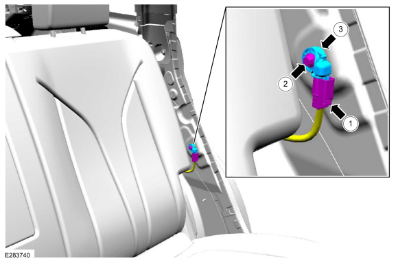
Release the retainers and position the loadspace trim panel aside to access the side impact sensor.
.jpg) |
-
-
Disconnect the electrical connector.
-
Remove the bolt.
Torque: 97 lb.in (11 Nm)
-
Remove the C-pillar side impact sensor.
-
Disconnect the electrical connector.
 |
Installation
-
NOTE: The C-pillar side impact sensor mating surfaces must be smooth and allow for a flush attachment to each other.
To install, reverse the removal procedure.
-
Repower the SRS .
Refer to: Supplemental Restraint System (SRS) Repowering (501-20 Supplemental Restraint System) .
 Clockspring. Removal and Installation
Removal
WARNING:
The following procedure prescribes critical repair steps
required for correct restraint system operation during a crash. Follow
all notes and steps carefully...
 Driver Airbag. Removal and Installation
Removal
WARNING:
The following procedure prescribes critical repair steps
required for correct restraint system operation during a crash. Follow
all notes and steps carefully...
Other information:
Lincoln Nautilus 2018-2026 Service Manual: Parking Aid. Diagnosis and Testing
Diagnostic Trouble Code (DTC) Chart Diagnostics in this manual assume a certain skill level and knowledge of Ford-specific diagnostic practices. REFER to: Diagnostic Methods (100-00 General Information, Description and Operation). Module DTC Description Action PAM B1303:13 Park Assist Switch: Circuit Open GO to Pinpoint Test D PAM B1303:9E Park Assist Switch: Stuck On GO..
Lincoln Nautilus 2018-2026 Owners Manual: Automatic Return to Park (P)
What Is Automatic Return to Park (P) Your vehicle shifts into park (P) if you attempt to exit your vehicle without the transmission in park (P). How Does Automatic Return to Park (P) Work Your vehicle shifts into park (P) when your vehicle is stationary and any of the following occur: You switch the vehicle off. You open the driver door with your seatbelt unlatched. You unlatch the drive..
Categories
- Manuals Home
- 1st Generation Nautilus Owners Manual
- 1st Generation Nautilus Service Manual
- Auto-Start-Stop
- Child Safety Locks
- Programming the Garage Door Opener to Your Garage Door Opener Motor
- New on site
- Most important about car
Replacing the Rear Wiper Blades
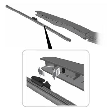
Note: Do not hold the wiper blade to lift the wiper arm.
Remove the wiper blade.