Lincoln Nautilus: Climate Control System - General Information / Evaporator Inlet and Outlet Manifold - 2.0L EcoBoost (184kW/250PS) – MI4. Removal and Installation
Lincoln Nautilus 2018-2026 Service Manual / Electrical / Climate Control System / Climate Control System - General Information / Evaporator Inlet and Outlet Manifold - 2.0L EcoBoost (184kW/250PS) – MI4. Removal and Installation
Removal
NOTICE: During the removal of components, cap, tape or otherwise appropriately protect all openings to prevent the ingress of dirt or other contamination. Remove protective materials prior to installation.
NOTE: Removal steps in this procedure may contain installation details.
-
Recover the refrigerant. Refer to the appropriate Recovery procedure in Group 412.
-
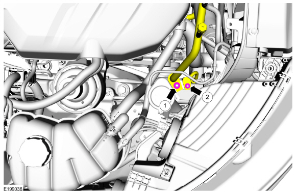
Remove the A/C compressor inlet line nut and the condenser outlet line nut and disconnect the fittings.
-
Make sure to cover any open ports to prevent debris from entering the system.
Torque:
1: 159 lb.in (18 Nm)
2: 80 lb.in (9 Nm)
-
Make sure to cover any open ports to prevent debris from entering the system.
 |
-
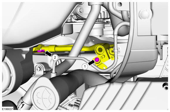
Remove the evaporator inlet and outlet manifold bracket bolt and nut.
Torque:
1: 106 lb.in (12 Nm)
2: 18 lb.in (2 Nm)
 |
-
Remove the air cleaner outlet pipe.
Refer to: Air Cleaner Outlet Pipe (303-12A Intake Air Distribution and Filtering - 2.0L EcoBoost (184kW/250PS) – MI4, Removal and Installation).
-
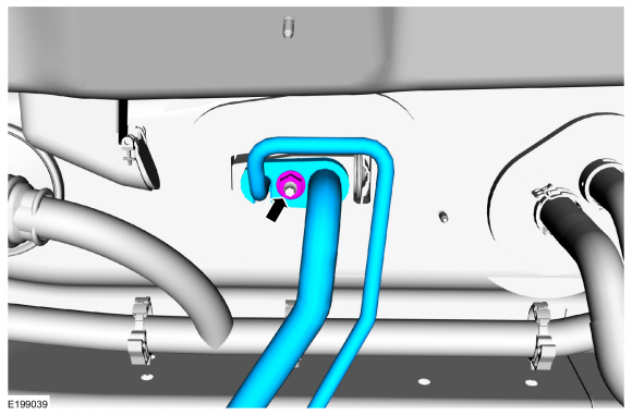
Remove the nut and remove the evaporator inlet and outlet manifold.
-
Make sure to cover any open ports to prevent debris from entering the system.
Torque: 159 lb.in (18 Nm)
-
Make sure to cover any open ports to prevent debris from entering the system.
 |
Installation
-
To install, reverse the removal procedure.
-
NOTICE: Only use the specified material to lubricate the seals.
Install and lubricate new O-ring seals. Refer to the appropriate Specifications in Group 412.
-
Lubricate the refrigerant system with the correct amount
of clean PAG oil. Refer to the appropriate Refrigerant Oil Adding
procedure in Group 412.
 Evaporator. Removal and Installation
Removal
Remove the climate control housing.
Refer to: Climate Control Housing (412-00 Climate Control System - General Information)
.
Remove the heater tube dash panel seal...
 Evaporator Temperature Sensor. Removal and Installation
Removal
NOTE:
The evaporator temperature sensor is available only as part of the climate control housing.
Remove the climate control housing...
Other information:
Lincoln Nautilus 2018-2026 Service Manual: Warning Chimes - Overview. Description and Operation
Overview The warning chimes provide the driver with audible warnings that act as reminders and supplemental alerts to visual IPC indications such as gauges, indicators and message center warnings. The IPC controls all warning chimes based on messages received from external modules...
Lincoln Nautilus 2018-2026 Service Manual: Rear Door Window Control Switch. Removal and Installation
Removal NOTE: LH side shown, RH side similar. Remove the rear door window control switch. Remove the rear door window control switch and the bezel assembly. Disconnect the rear door window control switch electrical connector...
Categories
- Manuals Home
- 1st Generation Nautilus Owners Manual
- 1st Generation Nautilus Service Manual
- Opening the Liftgate
- Locating the Pre-Collision Assist Sensors
- Engine Oil Capacity and Specification - 2.0L
- New on site
- Most important about car
Locating the Pre-Collision Assist Sensors

If a message regarding a blocked sensor or camera appears in the information display, something is obstructing the radar signals or camera images. The radar sensor is behind the fascia cover in the center of the lower grille. With a blocked sensor or camera, the system may not function, or performance may reduce. See Pre-Collision Assist – Information Messages.
Copyright © 2026 www.linautilus.com