Lincoln Nautilus: Exterior Lighting / Exterior Lighting - System Operation and Component Description. Description and Operation
System Operation
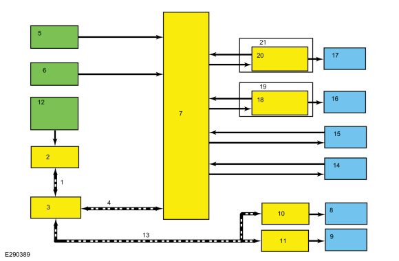
Headlamps
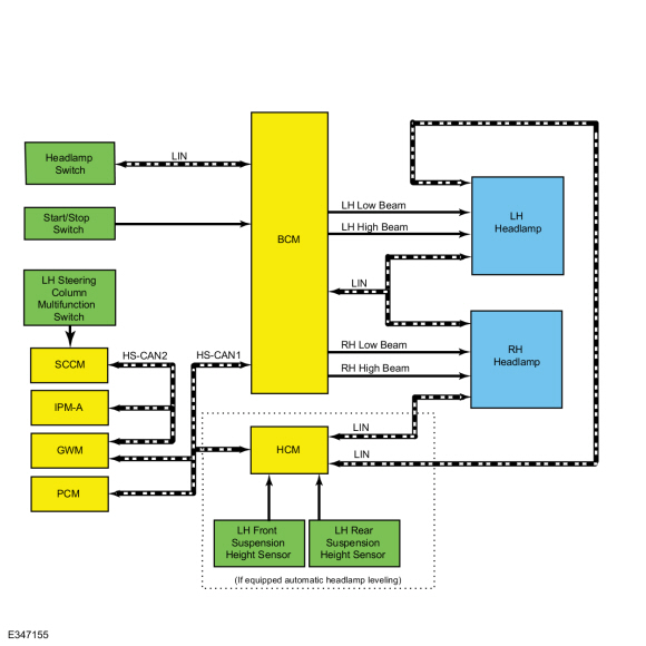
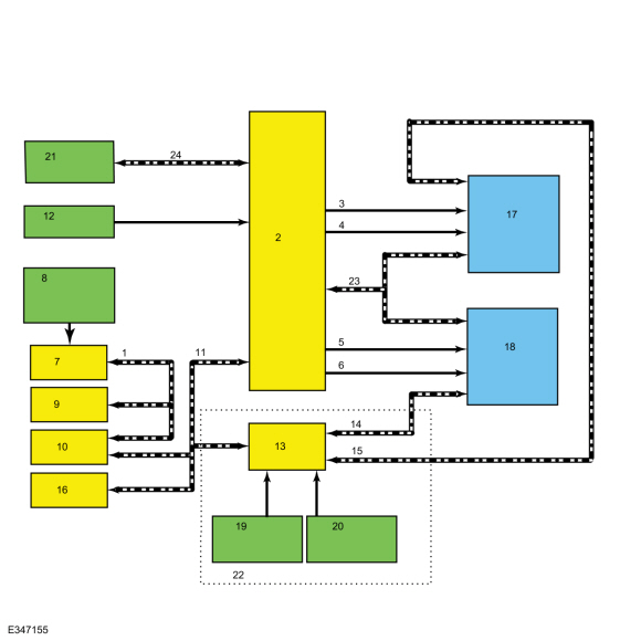
System Diagram
| Item | Description |
|---|---|
| 1 | HS-CAN2 |
| 2 | BCM |
| 3 | LH low beam |
| 4 | LH high beam |
| 5 | RH low beam |
| 6 | RH high beam |
| 7 | SCCM |
| 8 | LH steering column multifunction switch |
| 9 | IPMA |
| 10 | GWM |
| 11 | HS-CAN1 |
| 12 | Start/Stop switch |
| 13 | HCM |
| 14 | LIN |
| 15 | LIN |
| 16 | PCM |
| 17 | LH headlamp |
| 18 | RH headlamp |
| 19 | LH front suspension height sensor |
| 20 | LH rear suspension height sensor |
| 21 | Headlamp switch |
| 22 | (If equipped automatic headlamp leveling) |
| 23 | LIN |
| 24 | LIN |
Network Message Chart
BCM Network Input Messages
| Broadcast Message | Originating Module | Message Purpose |
|---|---|---|
| Headlamp flash to pass status | GWM | Indicates to the BCM a request for the high beams or flash-to-pass. |
| Auto high beam request | IPMA | Indicates to the BCM a request for the high beams based on the IPMA camera input. |
Low Beams
The headlamp switch sends a status message over the LIN circuit to the BCM to indicate the headlamp switch status (position or a fault with the headlamp switch). The BCM turns the parking lamps and headlamps on when the ignition is in RUN and the BCM detects a fault from the headlamp switch or wiring. This is normal behavior of the BCM when a fault has been detected with the inputs from the headlamp switch.
When the vehicle is in ON, the BCM supplies voltage to the headlamp LED driver module attached to each headlamp assembly through the low beam headlamp circuit. The headlamp LED driver module is used to control the low beam Light Emitting Diodes (LEDs).
When the BCM receives a message requesting the headlamps on, it sends a low beam message over the LIN circuit to the headlamp LED driver module attached to each headlamp assembly.
The BCM
also provides Field Effect Transistor (FET) protection of the low beam
output circuits. When an excessive current draw is detected, the BCM disables the affected circuit driver.
Refer
to: Module Controlled Functions - System Operation and Component
Description (419-10 Multifunction Electronic Modules, Description and
Operation).
High Beams
The SCCM monitors the LH steering column multifunction switch for a high beam request. When the LH steering column multifunction switch is in the HIGH BEAMS position, the SCCM sends a message over the HS-CAN2 to the GWM , then the GWM sends the message to the BCM over the HS-CAN1 .
When the low beams are on and the BCM receives a request for high beams, the low beam Light Emitting Diodes (LEDs) remains powered on and 2 high beam Light Emitting Diodes (LEDs) are also illuminated. This changes the headlamp beam pattern to illuminate a greater distance.
When the vehicle is in ON, the BCM supplies voltage to the headlamp LED driver module attached to each headlamp assembly through the high beam headlamp circuit. The headlamp LED driver module is used to control the high beam Light Emitting Diodes (LEDs).
The BCM
also provides Field Effect Transistor (FET) protection of the exterior
lamps switched voltage and high beam output circuits. When an excessive
current draw is detected, the BCM disables the affected circuit driver.
Refer
to: Module Controlled Functions - System Operation and Component
Description (419-10 Multifunction Electronic Modules, Description and
Operation).
Automatic High Beams
The automatic high beam system uses the IPMA camera to monitor surrounding traffic conditions and high beam usage. The camera is part of the IPMA . The IPMA communicates light information over the HS-CAN2 to the GWM then the GWM sends the information to the BCM over the HS-CAN1 .
The automatic high beam feature is active only when the headlamp switch is in the AUTOLAMPS position.
During nighttime driving, the automatic high beam system automatically turns the high beams on if it is dark enough and no other traffic is present. When the system detects an approaching vehicle's headlamps or a preceding vehicle's rear lamps, the system turns off the high beams. When the approaching vehicle's headlamps or the preceding vehicle's rear lamps are no longer detected, the high beams automatically turn back on.
The IPMA turns the high beam headlamps on when the following conditions are met:
- The feature has been enabled using the message center
- The headlamp switch is in the AUTOLAMPS position and the autolamps feature has turned the exterior lamps on
- The vehicle speed is greater than 51 km/h (32 mph)
- The IPMA determines the ambient lighting conditions are dark enough
- The IPMA does not detect any light source that can be interpreted as an illuminated vehicle lamp
The IPMA turns the high beams off if any of the following occur:
- The IPMA detects any light source that can be interpreted as an illuminated vehicle lamp
- The IPMA determines the ambient lighting conditions are not dark enough
- The vehicle speed falls below 44 km/h (27 mph)
- The autolamps are turned off
- The IPMA determines the view is blocked
Flash-To-Pass
The SCCM monitors the LH steering column multifunction switch for a flash-to-pass request. When the LH steering column multifunction switch is in the FLASH-TO-PASS position, the SCCM sends a message over the HS-CAN2 to the GWM then the GWM sends the message to the BCM over the HS-CAN1 .
When the ignition is in RUN and the flash-to-pass is requested, the high beams are activated as long as the LH steering column multifunction switch is held in the flash-to-pass position.
Headlamp Exit Delay
When the ignition is OFF and the LH steering column multifunction switch is placed in the FLASH-TO-PASS position and released, the parking lamps and low beams are illuminated. They remain illuminated until:
- 3 minutes have elapsed with a door open.
- 30 seconds have elapsed after all doors are closed.
- the LH steering column multifunction switch is placed in the flash-to-pass position again.
- the ignition switches to RUN.
Within the 30 second delay and all the doors closed, opening any door results in the 3 minute timer restarting.
Automatic Headlamp Leveling
The headlamp beam height is automatically adjusted according to vehicle load, speed, acceleration and braking data received from the ABS module, PCM and the VDM .
The front lighting uses a HCM to command the up/down aiming of the headlamp adaptive lighting LED through the LIN to the headlamp assemblies. The headlamp assemblies contain a module that receive the messages through the LIN from the HCM .
Depending on the inputs received (steering wheel angle and vehicle speed for example), the HCM can command the height at which the headlamp LED is aimed (up or down) to improve nighttime visibility. Automatic headlamp leveling is activated when the headlamp switch is in the HEADLAMPS or AUTOLAMPS position.
When the adaptive front lighting module first receives voltage when the ignition is ON, the and adaptive front lighting module commands the headlamps up and down to initialize the system. During the initialization, the HCM runs diagnostics on the system and set Diagnostic Trouble Codes (DTCs) for applicable system faults.
DRL
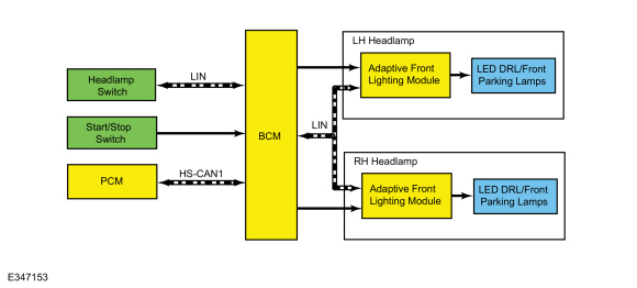
System Diagram
| Item | Description |
|---|---|
| 1 | BCM |
| 2 | Headlamp switch |
| 3 | HS-CAN1 |
| 4 | Start/Stop switch |
| 5 | PCM |
| 6 | LIN |
| 7 | LED DRL /front parking lamps |
| 8 | Adaptive front lighting module |
| 9 | LH headlamp |
| 10 | Adaptive front lighting module |
| 11 | RH headlamp |
| 12 | LED DRL /front parking lamps |
| 13 | LIN |
Network Message Chart
BCM Network Input Messages
| Broadcast Message | Originating Module | Message Purpose |
|---|---|---|
| Gear position | PCM | Indicates the GSM request to the BCM . When the GSM has selected any position other than park, the BCM activates the DRL . |
DRL
The DRL system illuminates the LED DRL /front parking lamps at full intensity in the headlamp assembly when the ignition is on, the headlamp switch is in the OFF or AUTOLAMPS position and the headlamps have not been turned on by the autolamp system.
When the vehicle is in ON, the BCM supplies voltage to the adaptive front lighting module attached to each headlamp assembly. This adaptive front lighting module is used to control the LED DRL /front parking lamps.
The BCM monitors the ignition status, the headlamp switch and autolamp status.
There are two types of DRL , conventional (where it is required) and configurable.
When equipped with conventional DRL , the DRL are active in any headlamp switch position except the HEADLAMPS position.
The conventional DRL are activated when the following conditions are met:
- the ignition is ON
- the headlamps switch is in OFF, PARKLAMPS or AUTOLAMPS position and the headlamps have not been turned on by the autolamp system.
- the transmission is not in PARK
When equipped with configurable DRL , the DRL may be enabled through the IPC message center. When enabled, the DRL are active only in the AUTOLAMPS headlamp position. When autolamps request the headlamps on, the DRL are de-activated.
The configurable DRL are activated when the following conditions are met:
- the ignition is ON.
- the headlamps switch is in AUTOLAMPS position and the headlamps have not been turned on by the autolamp system.
- the transmission is not in PARK.
When the transmission is in not in PARK, the PCM sends a message over the HS-CAN1 to the BCM indicating the transmission is not in PARK.
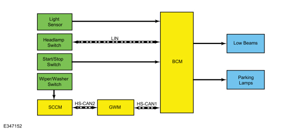
Autolamps
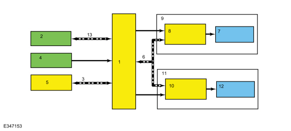
System Diagram
.jpg)
| Item | Description |
|---|---|
| 1 | BCM |
| 2 | Headlamp switch |
| 3 | Light sensor |
| 4 | Low beams |
| 5 | Start/Stop switch |
| 6 | SCCM |
| 7 | GWM |
| 8 | HS-CAN1 |
| 9 | HS-CAN2 |
| 10 | Wiper/Washer switch |
| 11 | Parking lamps |
| 12 | LIN |
Network Message Chart
BCM Network Input Messages
| Broadcast Message | Originating Module | Message Purpose |
|---|---|---|
| Front wiper status | SCCM | The BCM uses the wiper status information for the operation of the wiper activated headlamps feature. |
Autolamps
The headlamp switch sends a status message over the LIN circuit to the BCM to indicate the headlamp switch status (position or a fault with the headlamp switch). The BCM turns the parking lamps and headlamps on when the ignition is in RUN and the BCM detects a fault from the headlamp switch or wiring. This is normal behavior of the BCM when a fault has been detected with the inputs from the headlamp switch.
The BCM monitors the light sensor with a voltage signal. The light sensor input to the BCM varies with the ambient light conditions.
The BCM monitors the headlamp switch circuits to indicate the headlamp switch position.
When the BCM receives a headlamp switch status indicating a request for the autolamps, the BCM monitors the light sensor for the ambient light condition. If the BCM determines the ambient light level is dark, the BCM illuminates the exterior lamps.
Headlamps On With Wipers On Function
When the headlamp switch is in the autolamps position, the exterior lamps turn on when the front wipers are in low or high. This feature does not activate the exterior lamps during a mist wipe, while the wipers are on to clear washer fluid during a wash condition or if the wipers are in automatic or intermittent modes.
The exterior lamps turn off when the ignition switches OFF or to ON mode, the headlamp switch is placed in the OFF position, or the front wipers are turned off. The exception to this is when the exterior lights are on because of darkness determined by the autolamp system.
Stoplamps
System Diagram
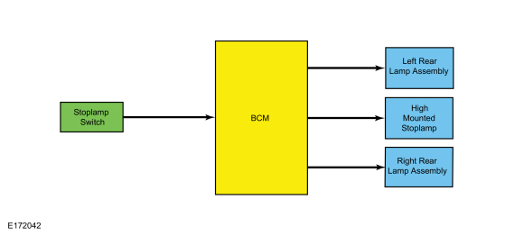
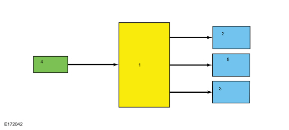
| Item | Description |
|---|---|
| 1 | BCM |
| 2 | LH rear lamp assembly |
| 3 | RH rear lamp assembly |
| 4 | Stoplamp switch |
| 5 | High mounted stoplamp |
Stoplamps
The BCM monitors the input from the stoplamp switch. When the brake pedal is applied, voltage is routed to the BCM , indicating a request for the stoplamps. The BCM then supplies voltage to the stoplamps.
The BCM does not activate the stoplamps when the ignition is in OFF.
The BCM uses 3 separate output circuits. The LH stoplamp output circuit, RH stoplamp output circuit and high-mounted stoplamp output circuit.
The BCM
also provides Field Effect Transistor (FET) protection of the stoplamp
output circuits. When an excessive current draw is detected, the BCM disables the affected stoplamp circuit driver.
Refer
to: Module Controlled Functions - System Operation and Component
Description (419-10 Multifunction Electronic Modules, Description and
Operation).
Turn Signal and Hazard Lamps
System Diagram
.jpg)
| Item | Description |
|---|---|
| 1 | HS-CAN2 |
| 2 | SCCM |
| 3 | GWM |
| 4 | HS-CAN1 |
| 5 | Start/Stop switch |
| 6 | Hazard switch |
| 7 | BCM |
| 8 | LH exterior mirror |
| 9 | RH exterior mirror |
| 10 | DDM |
| 11 | PDM |
| 12 | LH steering column multifunction switch |
| 13 | MS-CAN |
| 14 | RH rear turn lamp |
| 15 | LH rear turn lamp |
| 16 | RH front turn lamp |
| 17 | LH front turn lamp |
| 18 | Adaptive front lighting module |
| 19 | RH headlamp |
| 20 | Adaptive front lighting module |
| 21 | LH headlamp |
Network Message Chart
BCM Network Input Messages
| Broadcast Message | Originating Module | Message Purpose |
|---|---|---|
| Turn signal switch status | GWM | Indicates the turn signal stalk position on the LH steering column multifunction switch (left/right lane change or turn signal on or off). The BCM activates the left/right turn signals based on this input. |
DDM and PDM Network Input Messages
| Broadcast Message | Originating Module | Message Purpose |
|---|---|---|
| Turn indication request | BCM | A command to the DDM or PDM to activate/deactivate the exterior mirror turn indicator. |
Turn Signals - Front
The SCCM monitors the LH steering column multifunction switch position. When the LH steering column multifunction switch is in the LH TURN or RH TURN position, the SCCM sends a message over the HS-CAN2 to the GWM then the GWM sends the message to the BCM over the HS-CAN1 indicating a request for the LH or RH turn signal.
When the ignition is ON, the BCM supplies voltage to the adaptive front lighting module through the turn lamp voltage output circuit to power the turn lamp Light Emitting Diodes (LEDs) when commanded on.
When the BCM receives a request for a turn signal, it sends a message over the LIN circuit to the adaptive front lighting module attached to each headlamp assembly. The turn lamps are Light Emitting Diodes (LEDs) and have an outage circuit that tells the BCM when the Light Emitting Diodes (LEDs) are inoperative. During normal operation, when the adaptive front lighting module applies voltage to the turn Light Emitting Diodes (LEDs), the feedback circuit sends the same voltage back to the BCM through the outage circuit. If the Light Emitting Diodes (LEDs) are inoperative the BCM does not receive this voltage feedback through the outage circuit.
The BCM
also provides Field Effect Transistor (FET) protection of the turn
lamp output circuits. When an excessive current draw is detected, the BCM disables the affected turn lamp circuit driver.
Refer
to: Module Controlled Functions - System Operation and Component
Description (419-10 Multifunction Electronic Modules, Description and
Operation).
Turn Signals - Rear
The SCCM monitors the LH steering column multifunction switch position. When the LH steering column multifunction switch is in the LH TURN or RH TURN position, the SCCM sends a message over the HS-CAN2 to the GWM then the GWM sends the message to the BCM over the HS-CAN1 indicating a request for the LH or RH turn signal.
When the BCM receives a request for a turn signal, the BCM supplies on/off voltage to the appropriate rear turn lamp Light Emitting Diodes (LEDs). The turn lamps are Light Emitting Diodes (LEDs) and have an outage circuit that tells the BCM when the Light Emitting Diodes (LEDs) are inoperative. During normal operation, when voltage is applied to the turn Light Emitting Diodes (LEDs), the feedback circuit sends the same voltage back to the BCM through the outage circuit. If the Light Emitting Diodes (LEDs) are inoperative the BCM does not receive this voltage feedback through the outage circuit.
The BCM
also provides Field Effect Transistor (FET) protection of the turn
lamp output circuits. When an excessive current draw is detected, the BCM disables the affected turn lamp circuit driver.
Refer
to: Module Controlled Functions - System Operation and Component
Description (419-10 Multifunction Electronic Modules, Description and
Operation).
Turn Signals - Exterior Mirrors
The SCCM monitors the LH steering column multifunction switch position. When the LH steering column multifunction switch is in the LH TURN or RH TURN position, the SCCM sends a message over the HS-CAN2 to the GWM then the GWM sends the message to the BCM over the HS-CAN1 indicating a request for the LH or RH turn signal.
When the BCM receives a request for a turn signal, the BCM sends a turn indicator command message over the HS-CAN1 to the GWM then the MS-CAN to the door modules for the exterior mirror turn lamps (if equipped).
Hazard Lamps
The BCM sends a voltage signal to the hazard flasher lamp switch to monitor for a hazard lamp function request. When the hazard flasher lamp switch is pressed, the voltage signal is routed to ground, indicating a request to activate or deactivate the hazard lamp function.
When the BCM receives a request for the hazard lamps, the BCM supplies on/off voltage to all the turn lamps.
The timed on/off cycle for the hazard lamps is approximately 70 times per minute, regardless of bulb outage.
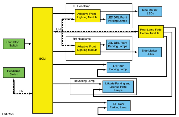
Parking, Rear, and License Plate Lamps
System Diagram
.jpg)
| Item | Description |
|---|---|
| 1 | BCM |
| 2 | Headlamp switch |
| 3 | RH rear parking lamp |
| 4 | LH rear parking lamp |
| 5 | Liftgate parking and license plate lamps |
| 6 | Start/Stop switch |
| 7 | Adaptive front lighting module |
| 8 | LH Headlamp |
| 9 | Side marker Light Emitting Diodes (LEDs) |
| 10 | LIN |
| 11 | Rear lamp fade control module |
| 12 | Adaptive front lighting module |
| 13 | RH Headlamp |
| 14 | Side marker Light Emitting Diodes (LEDs) |
| 15 | LED DRL /front parking lamps |
| 16 | LED DRL /front parking lamps |
| 17 | Reversing lamp |
| 18 | LIN |
Parking Lamps
The headlamp switch sends a status message over the LIN circuit to the BCM to indicate the headlamp switch status (position or a fault with the headlamp switch). The BCM turns the parking lamps and headlamps on when the ignition is in RUN and the BCM detects a fault from the headlamp switch or wiring. This is normal behavior of the BCM when a fault has been detected with the inputs from the headlamp switch.
For front parking lamps, when the BCM receives a request for parking lamps, the BCM sends a message over the LIN circuit to the adaptive front lighting module to dim the LED DRL /front parking lamps.
For rear parking lamps, when the BCM receives a request for a parking lamps, the BCM supplies voltage to the rear parking lamps.
The BCM
also provides Field Effect Transistor (FET) protection of the parking
lamps output circuits. When an excessive current draw is detected, the BCM disables the affected parking lamps circuit driver.
Refer
to: Module Controlled Functions - System Operation and Component
Description (419-10 Multifunction Electronic Modules, Description and
Operation).
Approach Detection
The approach detection feature is used to passively activate the illuminated entry feature while approaching the vehicle. Illuminated entry includes ramping up the illumination of the vehicles parking lamps.
Once illuminated entry is activated, the BCM sends a message over the LIN circuit to both adaptive front lighting modules (one mounted on each headlamp) and to the rear lamp fade control module.
For front parking lamps, when the adaptive front lighting module receives the illuminated entry message from the BCM , the adaptive front lighting module ramps up the front parking lamps.
For rear parking lamps, when the rear lamp fade control module receives the illuminated entry message from the BCM , the rear lamp fade control module supplies a PWM voltage to the each rear and liftgate parking lamps to ramp up illumination.
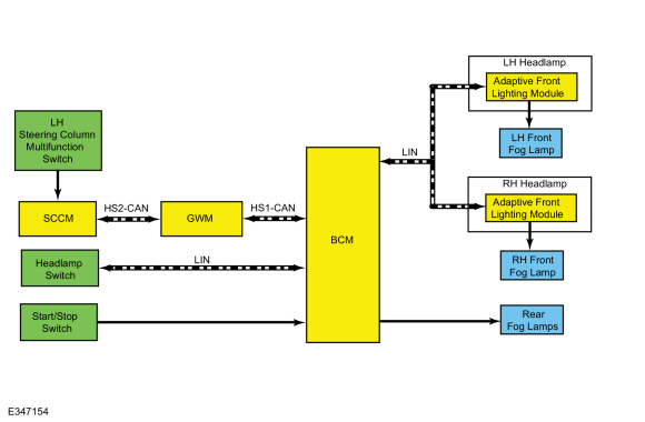
Fog Lamps
System Diagram
.jpg)
| Item | Description |
|---|---|
| 1 | BCM |
| 2 | Headlamp switch |
| 3 | RH front fog lamp |
| 4 | Start/Stop switch |
| 5 | SCCM |
| 6 | GWM |
| 7 | LH steering column multifunction switch |
| 8 | HS-CAN1 |
| 9 | HS-CAN2 |
| 10 | LH headlamp |
| 11 | Adaptive front lighting module |
| 12 | LIN |
| 13 | LH front fog lamp |
| 14 | RH headlamp |
| 15 | Adaptive front lighting module |
| 16 | Rear fog lamps |
| 17 | LIN |
Fog Lamps
The headlamp switch sends a status message over the LIN circuit to the BCM to indicate the headlamp switch status (position or a fault with the headlamp switch).
When the BCM receives a request for the front fog lamps it sends a message over the LIN circuit to the adaptive front lighting module attached to each headlamp assembly. When the adaptive front lighting module receives the front fog lamp request it supplies voltage to the front fog lamp Light Emitting Diodes (LEDs).
When the BCM receives input from the headlamp switch indicating a request for the rear fog lamp, the BCM provides voltage to the rear fog lamp.
The BCM
also provides Field Effect Transistor (FET) protection of the rear fog
lamp output circuit. When an excessive current draw is detected, the BCM disables the rear fog lamp output circuit driver.
Refer
to: Module Controlled Functions - System Operation and Component
Description (419-10 Multifunction Electronic Modules, Description and
Operation).
Reversing Lamps
System Diagram
.jpg)
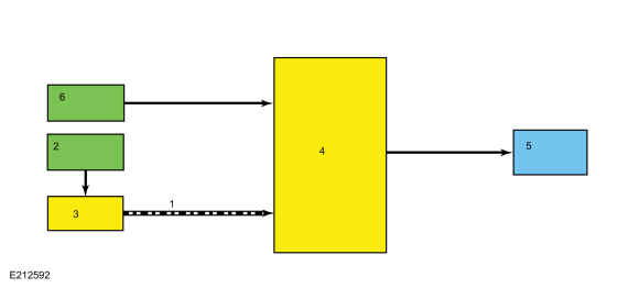
| Item | Description |
|---|---|
| 1 | HS-CAN1 |
| 2 | Transmission range sensor |
| 3 | PCM |
| 4 | BCM |
| 5 | Reversing lamp |
| 6 | Start/Stop switch |
Network Message Chart
BCM Network Input Messages
| Broadcast Message | Originating Module | Message Purpose |
|---|---|---|
| Gear position | PCM | Indicates the transmission is in reverse gear to the BCM . When the transmission is in REVERSE and the ignition in RUN, the BCM provides voltage to the reversing lamps. |
Reversing Lamps
When the transmission is in REVERSE, the PCM sends a message over the HS-CAN1 to the BCM indicating the transmission is in REVERSE. The BCM provides voltage to the reversing lamps when it receives the message that the transmission is in REVERSE and the ignition is in RUN.
The BCM
also provides Field Effect Transistor (FET) protection of the
reversing lamp output circuit. When an excessive current draw is
detected, the BCM disables the affected reversing lamps circuit driver.
Refer
to: Module Controlled Functions - System Operation and Component
Description (419-10 Multifunction Electronic Modules, Description and
Operation).
Trailer Lamps
System Diagram
.jpg)
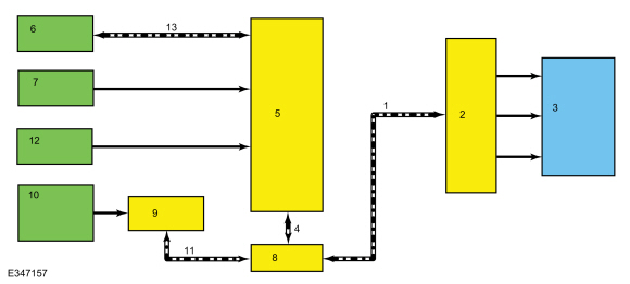
| Item | Description |
|---|---|
| 1 | MS-CAN |
| 2 | TRM |
| 3 | Trailer tow connector |
| 4 | HS-CAN1 |
| 5 | BCM |
| 6 | Headlamp switch |
| 7 | Stoplamp switch |
| 8 | GWM |
| 9 | SCCM |
| 10 | LH steering column multifunction switch |
| 11 | HS-CAN2 |
| 12 | Start/Stop switch |
| 13 | LIN |
Network Message Chart
TRM Network Input Messages
| Broadcast Message | Originating Module | Message Purpose |
|---|---|---|
| Turn signal switch status | SCCM | A command to the TRM to activate/deactivate the turn indicator output to the trailer tow connector. |
| Stoplamp request | BCM | A command to the TRM to activate/deactivate the stop lamps output to the trailer tow connector. |
| Parklamp status | GWM | A command to the TRM to activate/deactivate the park lamps output to the trailer tow connector. |
Trailer Stop-Turn Lamps
The SCCM monitors the LH multifunction switch position. When the LH multifunction switch is in the left or right turn position, the SCCM sends a message over the LIN to the BCM indicating a request for the LH or RH turn signal.
When the BCM receives a request for a turn signal, the BCM sends a turn indicator command message over the MS-CAN to the TRM to activate the requested turn indicator output to the trailer tow connector.
When the BCM receives input from the stoplamp switch indicating that the brake pedal is being pressed, the TRM receives a stoplamp activation signal from the BCM .
Trailer Parking Lamps
The headlamp switch sends a headlamp switch status message over the LIN to the BCM to indicate the headlamp switch status (position or a fault with the headlamp switch).
When the parking lamps or headlamps position is selected, the BCM sends a position light indication message over the MS-CAN to the TRM to activate the parking lamps output to the trailer tow connector.
Field Effect Transistor (FET) Protection
The TRM utilizes a Field Effect Transistor (FET) protective circuit strategy for its lamp output circuits. Output loads (current level) are monitored for excessive current (typically short circuits) and are shut down (turns off the voltage or ground provided by the module) when a fault event is detected.
A Field Effect Transistor (FET) is a type of transistor that the control module software uses to control and monitor current flow on module outputs. The Field Effect Transistor (FET) protection strategy prevents module damage in the event of excessive current flow.
Output loads (current level) are monitored for excessive current draw (typically short circuits). When a fault event is detected the Field Effect Transistor (FET) turns off and a short circuit DTC sets. The module resets the Field Effect Transistor (FET) protection and allows the circuit to function when the fault is corrected or the ignition state is cycled off and then back on.
When the excessive circuit load occurs often enough, the module shuts down the output until a repair procedure is carried out. Each Field Effect Transistor (FET) protected circuit has 3 predefined levels of short circuit tolerance based on a module lifetime level of fault events based upon the durability of the Field Effect Transistor (FET).
When each level is reached, the DTC associated with the short circuit sets along with DTC U1000:00. These Diagnostic Trouble Codes (DTCs) can be cleared using the module on-demand self-test, then the Clear DTC operation on the scan tool (if the on-demand test shows the fault corrected). The module never resets the fault event counter to zero and continues to advance the fault event counter as short circuit fault events occur.
If the number of short circuit fault events reach the third level, then Diagnostic Trouble Codes (DTCs) U1000:00 and U3000:49 set along with the associated short circuit DTC . DTC U3000:49 cannot be cleared and the module must be replaced after the repair.
Component Description
Headlamp Assembly
The headlamps utilize the adaptive front lighting module (mounted to the headlamp assembly) that is used to control the headlamp daytime running/signature lamp Light Emitting Diodes (LEDs), front side marker lamps and front fascia mounted daytime running/supplemental parking lamps.
For The High Intensity Discharge (HID) headlamps, the headlamps utilize a ballast to power the High Intensity Discharge (HID) bulb. The headlamp assembly has an integrated solenoid activated shutter which changes the headlamp beam pattern when activated. The solenoid and shutter are not serviceable separately from the headlamp assembly. The headlamp assembly is provided power on independent circuits for the low beams and the high beams.
For LED headlamps, the headlamps utilize a ballast (headlamp LED driver module, mounted to the headlamp assembly) that is used to control the low and high beam Light Emitting Diodes (LEDs).
Exterior lamps are vented to accommodate normal changes in pressure. Condensation can be a natural by-product of this design. When moist air enters the lamp assembly through the vents, there is a possibility that condensation can occur if the temperature is cold. When normal condensation occurs, a thin mist forms on the interior of the lens. The thin mist eventually clears and exits through the vents during normal operation. The amount of time it takes to clear the lens of acceptable mist varies with ambient humidity and lamp types. Normal condensation clears from any lamp in 48 hours under dry conditions.
Do not replace a lamp assembly with acceptable levels of condensation such as:
- presence of thin mist (no streaks, drip marks or droplets are present)
- fine mist covers less than 50% of the lens
Examples of unacceptable moisture (usually caused by a lamp housing leak):
- water puddling inside the lamp
- large water droplets, drip marks or streaks present on the interior of the lens
Headlamp Switch
The headlamp switch sends a headlamp switch status message over the LIN to the BCM to indicate the headlamp switch status (position or a fault with the headlamp switch).
Light Sensor
The BCM sends a voltage signal to the light sensor. The light sensor provides resistance between the voltage signal and ground. The resistance varies depending on the amount of ambient light detected by the light sensor. The brighter the ambient light, the lower the resistance. By varying the resistance, the BCM can determine the amount of ambient light.
Stoplamp Switch
The stoplamp switch is a normally open switch and is provided voltage at all times. When the brake pedal is applied, the switch closes and routes voltage to the BCM .
 Exterior Lighting - Overview. Description and Operation
Overview
Headlamps
The LED headlamp system consists of 3 low beam and 2 high beam non-replaceable Light Emitting Diodes (LEDs). The LED
DRL /front parking lamps are integrated into the headlamp assembly and are not individually replaceable...
 Autolamps. Diagnosis and Testing
DTC Charts
DTC Chart: BCM
Diagnostics in this manual assume a certain skill level and knowledge of Ford-specific diagnostic practices. REFER to: Diagnostic Methods (100-00 General Information, Description and Operation)...
Other information:
Lincoln Nautilus 2018-2026 Service Manual: Roof Panel. Removal and Installation
Special Tool(s) / General Equipment Resistance Spotwelding Equipment Scraper for Straight Edges Spherical Cutter Hot Air Gun Spot Weld Drill Bit Locking Pliers Materials Name Specification Metal Bonding AdhesiveTA-1, TA-1-B, 3M™ 08115, LORD Fusor® 108B, Henkel Teroson EP 5055 - Seam SealerTA-2-B, 3M™ 08308, LORD Fusor® 803DTM - ..
Lincoln Nautilus 2018-2026 Service Manual: Brake Disc. Removal and Installation
Materials Name Specification Motorcraft® Metal Brake Parts CleanerPM-4-A, PM-4-B, APM-4-C - Removal NOTE: Removal steps in this procedure may contain installation instructions. WARNING: Service actions on vehicles equipped with electronic parking brakes may cause unexpected parking brake application, which could result in injury to hands or finge..
Categories
- Manuals Home
- 1st Generation Nautilus Owners Manual
- 1st Generation Nautilus Service Manual
- Auto-Start-Stop
- Fuel Quality
- Massage Seats
- New on site
- Most important about car
Parking Aid Indicators. Parking Aids – Troubleshooting
Parking Aid Indicators
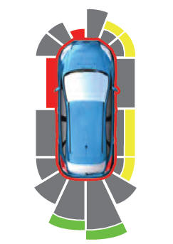
The system provides object distance indication through the information and entertainment display.
As the distance to the object decreases, the indicator waves and the lines move toward the vehicle icon. If there is no object detected, the distance indicator lines are grey.