Lincoln Nautilus: Rear End Sheet Metal Repairs / Front Floor Panel Side Member. Removal and Installation
Special Tool(s) / General Equipment
| Resistance Spotwelding Equipment | |
| Scraper for Straight Edges | |
| Hot Air Gun | |
| 8 mm Drill Bit | |
| MIG/MAG Welding Equipment | |
| Spot Weld Drill Bit | |
| Locking Pliers |
Materials
| Name | Specification |
|---|---|
| Seam Sealer TA-2-B, 3M™ 08308, LORD Fusor® 803DTM |
- |
Removal
NOTE: Roof removed for clarity.
NOTE: Left hand (LH) side shown, right hand (RH) side similar.
NOTE: Factory welds may be substituted with resistance or metal inert gas (MIG) plug welds. Resistance welds may not be placed directly over original location. They must be placed adjacent to original location and match factory welds in quantity. Metal inert gas (MIG) plug welds must equal factory welds in both location and quantity.
NOTE: Adequately protect all adjacent areas against cutting, grinding and welding procedures.
-
Depower the SRS .
Refer to: Supplemental Restraint System (SRS) Depowering (501-20B Supplemental Restraint System, General Procedures).
-
If Required:
Dimensionally restore the vehicle to pre-damage condition.
Refer to: Body and Frame (501-26 Body Repairs - Vehicle Specific Information and Tolerance Checks, Description and Operation).
-
Remove the following items:
-
Remove the front seat.
Refer to: Front Seat (501-10A Front Seats, Removal and Installation).
-
Remove the B-pillar trim panels.
Refer to: B-Pillar Trim Panel (501-05 Interior Trim and Ornamentation, Removal and Installation).
-
Remove the instrument panel.
Refer to: Instrument Panel (501-12 Instrument Panel and Console, Removal and Installation).
-
Remove the reinforcement.
Refer to: B-Pillar and Reinforcement (501-29 Side Panel Sheet Metal Repairs, Removal and Installation).
-
Remove the A-pillar reinforcement.
Refer to: A-Pillar Outer Panel Section and Reinforcement (501-29 Side Panel Sheet Metal Repairs, Removal and Installation).
-
Remove the front side member.
Refer to: Front Side Member and Fender Apron Panel LH (501-27 Front End Sheet Metal Repairs, Removal and Installation).
-
Remove the inner floor panel front reinforcement.
Refer to: Front Floor Panel Upper Front Crossmember (501-30 Rear End Sheet Metal Repairs, Removal and Installation).
-
Remove the inner floor panel rear reinforcement.
Refer to: Front Floor Panel Upper Rear Crossmember (501-30 Rear End Sheet Metal Repairs, Removal and Installation).
-
Remove the front seat.
-
Position the carpet and all wiring harnesses away from the working area.
-
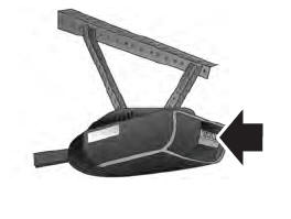
Remove the seam sealer.
Use the General Equipment: Hot Air Gun
Use the General Equipment: Scraper for Straight Edges
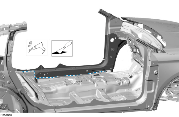 |
-
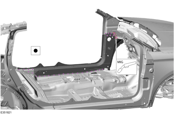
Remove the welds.
Use the General Equipment: Spot Weld Drill Bit
.jpg) |
-
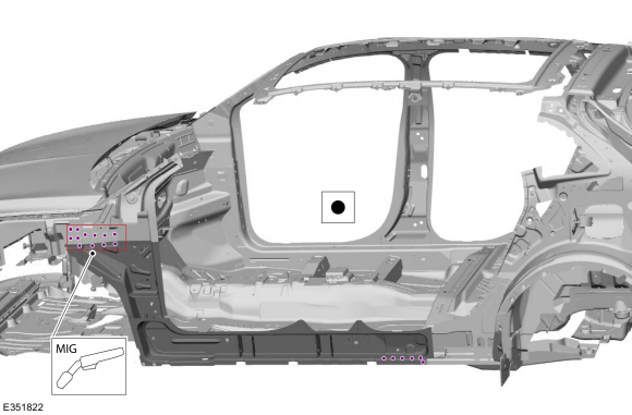
Remove the welds.
Use the General Equipment: Spot Weld Drill Bit
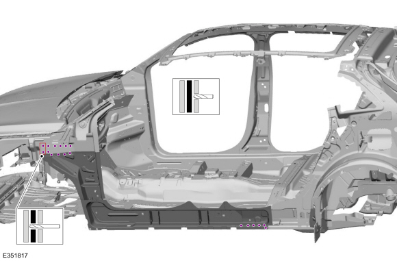 |
-
NOTE: Pay particular attention the location of adhesives, sealers and NVH materials to aid in installation.
Remove the front floor side member.
.jpg) |
Installation
NOTE: Roof removed for clarity.
NOTE: Left hand (LH) side shown, right hand (RH) side similar.
NOTE: Factory welds may be substituted with resistance or metal inert gas (MIG) plug welds. Resistance welds may not be placed directly over original location. They must be placed adjacent to original location and match factory welds in quantity. Metal inert gas (MIG) plug welds must equal factory welds in both location and quantity.
NOTE: Adequately protect all adjacent areas against cutting, grinding and welding procedures.
-
Drill plug weld holes as required in the replacement front floor panel side member.
Use the General Equipment: 8 mm Drill Bit
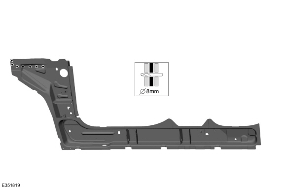 |
-
Install, properly position and clamp the side member.
Use the General Equipment: Locking Pliers
.jpg) |
-
Install the welds.
Use the General Equipment: Resistance Spotwelding Equipment
Use the General Equipment: MIG/MAG Welding Equipment
 |
-
Install the welds.
Use the General Equipment: Resistance Spotwelding Equipment
Use the General Equipment: MIG/MAG Welding Equipment
 |
-
Dress all welds as required using typical metal finishing techniques.
-
Seam Sealing:
All seams must be sealed to production level.
Material: Seam Sealer / TA-2-B, 3M™ 08308, LORD Fusor® 803DTM
.jpg) |
-
Refinish the entire repair using A Ford approved paint system.
-
Restore corrosion protection.
Refer to: Corrosion Prevention (501-25 Body Repairs - General Information, General Procedures).
-
Position all wiring harnesses and the carpet to original locations.
-
Install the following items:
-
Install the inner floor panel rear reinforcement.
Refer to: Front Floor Panel Upper Rear Crossmember (501-30 Rear End Sheet Metal Repairs, Removal and Installation).
-
Install the inner floor panel front reinforcement.
Refer to: Front Floor Panel Upper Front Crossmember (501-30 Rear End Sheet Metal Repairs, Removal and Installation).
-
Install the front side member.
Refer to: Front Side Member and Fender Apron Panel LH (501-27 Front End Sheet Metal Repairs, Removal and Installation).
-
Install the A-pillar reinforcement.
Refer to: A-Pillar Outer Panel Section and Reinforcement (501-29 Side Panel Sheet Metal Repairs, Removal and Installation).
-
Install the reinforcement.
Refer to: B-Pillar and Reinforcement (501-29 Side Panel Sheet Metal Repairs, Removal and Installation).
-
Install the instrument panel.
Refer to: Instrument Panel (501-12 Instrument Panel and Console, Removal and Installation).
-
Install the B-pillar trim panels.
Refer to: B-Pillar Trim Panel (501-05 Interior Trim and Ornamentation, Removal and Installation).
-
Install the front seat.
Refer to: Front Seat (501-10A Front Seats, Removal and Installation).
-
Install the inner floor panel rear reinforcement.
-
Repower the SRS .
Refer to: Supplemental Restraint System (SRS) Repowering (501-20B Supplemental Restraint System, General Procedures).
 Front Floor Panel Lower Reinforcement. Removal and Installation
Special Tool(s) /
General Equipment
8 mm Drill Bit
MIG/MAG Welding Equipment
Spot Weld Drill Bit
Locking Pliers
Materials
Name
Specification
Seam SealerTA-2-B, 3M™ 08308, LORD Fusor® 803DTM
-
Removal
NOTE:
Left hand (LH) side shown, right hand (RH) side similar...
 Front Floor Panel Upper Front Crossmember. Removal and Installation
Special Tool(s) /
General Equipment
8 mm Drill Bit
MIG/MAG Welding Equipment
Spot Weld Drill Bit
Locking Pliers
Materials
Name
Specification
Seam SealerTA-2-B, 3M™ 08308, LORD Fusor® 803DTM
-
Removal
NOTE:
Left hand (LH) side shown, right hand (RH) side similar...
Other information:
Lincoln Nautilus 2018-2026 Service Manual: Front Strut and Spring Assembly. Removal and Installation
Removal NOTICE: Suspension fasteners are critical parts that affect the performance of vital components and systems. Failure of these fasteners may result in major service expense. Use the same or equivalent parts if replacement is necessary. Do not use a replacement part of lesser quality or substitute design...
Lincoln Nautilus 2018-2026 Service Manual: Component Bleeding. General Procedures
Special Tool(s) / General Equipment Master Cylinder Bleeding Set Bleeding NOTICE: If the fluid is spilled on the paintwork, the affected area must be immediately washed down with cold water. Master Cylinder NOTE: When a new brake master cylinder has been installed, it should be primed to prevent air from entering the system...
Categories
- Manuals Home
- 1st Generation Nautilus Owners Manual
- 1st Generation Nautilus Service Manual
- Auto-Start-Stop
- Replacing the Rear Wiper Blades
- Opening the Liftgate
- New on site
- Most important about car
Programming the Garage Door Opener to Your Garage Door Opener Motor