Lincoln Nautilus: Rear End Sheet Metal Repairs / Front Floor Panel Lower Reinforcement. Removal and Installation
Special Tool(s) / General Equipment
| 8 mm Drill Bit | |
| MIG/MAG Welding Equipment | |
| Spot Weld Drill Bit | |
| Locking Pliers |
Materials
| Name | Specification |
|---|---|
| Seam Sealer TA-2-B, 3M™ 08308, LORD Fusor® 803DTM |
- |
Removal
NOTE: Left hand (LH) side shown, right hand (RH) side similar.
NOTE: Factory welds may be substituted with resistance or metal inert gas (MIG) plug welds. Resistance welds may not be placed directly over original location. They must be placed adjacent to original location and match factory welds in quantity. Metal inert gas (MIG) plug welds must equal factory welds in both location and quantity.
NOTE: Adequately protect all adjacent areas against cutting, grinding and welding procedures.
-
Depower the SRS .
Refer to: Supplemental Restraint System (SRS) Depowering (501-20B Supplemental Restraint System, General Procedures).
-
If Required:
Dimensionally restore the vehicle to pre-damage condition.
Refer to: Body and Frame (501-26 Body Repairs - Vehicle Specific Information and Tolerance Checks, Description and Operation).
-
Remove the underbody shield(s).
-
Relocate any fuel or brake lines away from the working area.
-
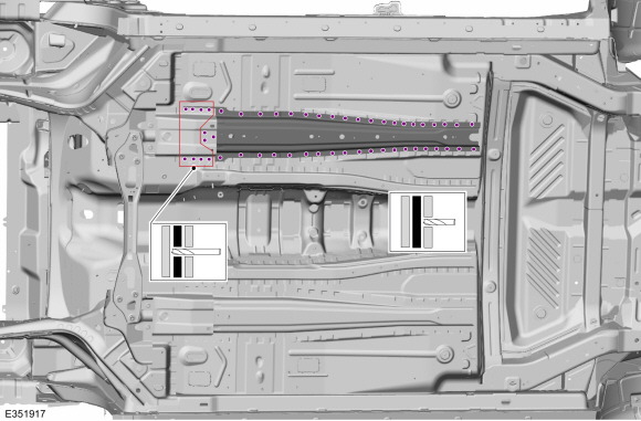
Remove the welds.
Use the General Equipment: Spot Weld Drill Bit
 |
-
NOTE: Pay particular attention the location of adhesives, sealers and NVH materials to aid in installation.
Remove the reinforcement.
.jpg) |
Installation
NOTE: Left hand (LH) side shown, right hand (RH) side similar.
NOTE: Factory welds may be substituted with resistance or metal inert gas (MIG) plug welds. Resistance welds may not be placed directly over original location. They must be placed adjacent to original location and match factory welds in quantity. Metal inert gas (MIG) plug welds must equal factory welds in both location and quantity.
NOTE: Adequately protect all adjacent areas against cutting, grinding and welding procedures.
-
Drill plug weld holes in the replacement reinforcement.
Use the General Equipment: 8 mm Drill Bit
.jpg) |
-
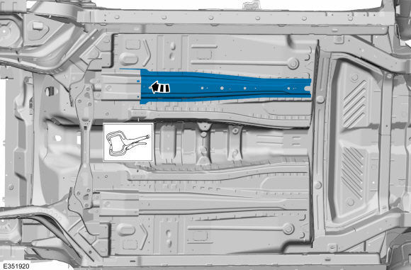
Install, properly position and clamp the lower reinforcement.
Use the General Equipment: Locking Pliers
 |
-
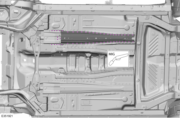
Install the welds.
Use the General Equipment: MIG/MAG Welding Equipment
 |
-
Dress all welds as required using typical metal finishing techniques.
-
Seam Sealing:
All seams must be sealed to production level.
Material: Seam Sealer / TA-2-B, 3M™ 08308, LORD Fusor® 803DTM
-
Refinish the entire repair using a Ford approved paint system.
-
Restore corrosion protection.
Refer to: Corrosion Prevention (501-25 Body Repairs - General Information, General Procedures).
-
Relocate any fuel or brake lines to original locations.
-
Install the underbody shield(s).
-
Repower the SRS .
Refer to: Supplemental Restraint System (SRS) Repowering (501-20B Supplemental Restraint System, General Procedures).
 Front Floor Panel Bracket and Support. Removal and Installation
Special Tool(s) /
General Equipment
8 mm Drill Bit
MIG/MAG Welding Equipment
Spot Weld Drill Bit
Locking Pliers
Materials
Name
Specification
Seam SealerTA-2-B, 3M™ 08308, LORD Fusor® 803DTM
-
Removal
NOTE:
The following components are available separately...
 Front Floor Panel Side Member. Removal and Installation
Special Tool(s) /
General Equipment
Resistance Spotwelding Equipment
Scraper for Straight Edges
Hot Air Gun
8 mm Drill Bit
MIG/MAG Welding Equipment
Spot Weld Drill Bit
Locking Pliers
Materials
Name
Specification
Seam SealerTA-2-B, 3M™ 08308, LORD Fusor® 803DTM
-
Removal
NOTE:
Roof removed for clarity...
Other information:
Lincoln Nautilus 2018-2026 Service Manual: Cruise Control - System Operation and Component Description. Description and Operation
System Operation Non-Adaptive Cruise Control Item Description 1 Brake switch assembly 2 IPC 3 Accelerator pedal 4 Deactivator switch 5 Stoplamp switch 6 SCCM 7 PCM 8 Cruise control switches 9 GWM 10 ABS module 11 RCM 12 Steering Effort Control Module (SECM) (adaptive steering) ..
Lincoln Nautilus 2018-2026 Service Manual: Cylinder Block Core Plug Replacement. General Procedures
Special Tool(s) / General Equipment 100-001 (T50T-100-A) Slide Hammer Materials Name Specification Motorcraft® Threadlock 262TA-26 WSK-M2G351-A6 Repair All core plugs NOTE: Cylinder block core plug shown, cylinder head core plug similar. Using the Slide Hammer and a commercially available body dent puller attachment or commercially available ..
Categories
- Manuals Home
- 1st Generation Nautilus Owners Manual
- 1st Generation Nautilus Service Manual
- Switching the Lane Keeping System On and Off. Switching the Lane Keeping System Mode
- Engine Oil Capacity and Specification - 2.0L
- Opening the Liftgate
- New on site
- Most important about car
Clearing the Garage Door Opener. Reprogramming the Garage Door Opener. Garage Door Opener Radio Frequencies
Clearing the Garage Door Opener