Lincoln Nautilus: Rear End Sheet Metal Repairs / Front Floor Panel Upper Rear Crossmember. Removal and Installation
Special Tool(s) / General Equipment
| 8 mm Drill Bit | |
| MIG/MAG Welding Equipment | |
| Spot Weld Drill Bit | |
| Locking Pliers |
Materials
| Name | Specification |
|---|---|
| Seam Sealer TA-2-B, 3M™ 08308, LORD Fusor® 803DTM |
- |
Removal
NOTE: Left hand (LH) side shown, right hand (RH) side similar.
NOTE: Roof and body side removed for clarity.
NOTE: Factory welds may be substituted with resistance or metal inert gas (MIG) plug welds. Resistance welds may not be placed directly over original location. They must be placed adjacent to original location and match factory welds in quantity. Metal inert gas (MIG) plug welds must equal factory welds in both location and quantity.
NOTE: Adequately protect all adjacent areas against cutting, grinding and welding procedures.
-
Depower the SRS .
Refer to: Supplemental Restraint System (SRS) Depowering (501-20B Supplemental Restraint System, General Procedures).
-
If Required:
Dimensionally restore the vehicle to pre-damage condition.
Refer to: Body and Frame (501-26 Body Repairs - Vehicle Specific Information and Tolerance Checks, Description and Operation).
-
Remove the following items:
-
Remove the front seat.
Refer to: Front Seat (501-10A Front Seats, Removal and Installation).
-
Remove the center console.
Refer to: Floor Console (501-12 Instrument Panel and Console, Removal and Installation).
-
Remove the B-pillar trim panel.
Refer to: B-Pillar Trim Panel (501-05 Interior Trim and Ornamentation, Removal and Installation).
-
Remove the front seat.
-
Position the carpet and all wiring harnesses away from the working area.
-
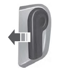
Remove the welds.
Use the General Equipment: Spot Weld Drill Bit
.jpg) |
-
Remove the welds.
Use the General Equipment: Spot Weld Drill Bit
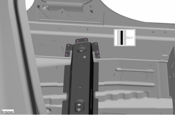 |
-
NOTE: Pay particular attention the location of adhesives, sealers and NVH materials to aid in installation.
Remove the crossmember.
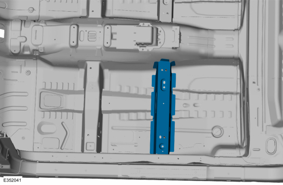 |
Installation
NOTE: Left hand (LH) side shown, right hand (RH) side similar.
NOTE: Roof and body side removed for clarity.
NOTE: Factory welds may be substituted with resistance or metal inert gas (MIG) plug welds. Resistance welds may not be placed directly over original location. They must be placed adjacent to original location and match factory welds in quantity. Metal inert gas (MIG) plug welds must equal factory welds in both location and quantity.
NOTE: Adequately protect all adjacent areas against cutting, grinding and welding procedures.
-
Drill plug weld holes in the replacement rear crossmember.
Use the General Equipment: 8 mm Drill Bit
.jpg) |
-
Install, properly position and clamp the rear crossmember.
Use the General Equipment: Locking Pliers
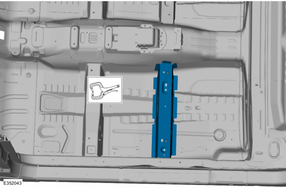 |
-
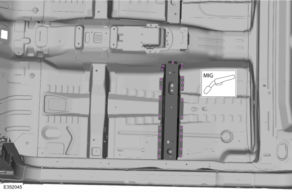
Install the welds.
Use the General Equipment: MIG/MAG Welding Equipment
.jpg) |
-
Install the welds.
Use the General Equipment: MIG/MAG Welding Equipment
 |
-
Dress all welds as required using typical metal finishing techniques.
-
Seam Sealing:
All seams must be sealed to production level.
Material: Seam Sealer / TA-2-B, 3M™ 08308, LORD Fusor® 803DTM
-
Refinish the entire repair using a Ford approved paint system.
-
Restore corrosion protection.
Refer to: Corrosion Prevention (501-25 Body Repairs - General Information, General Procedures).
-
Reposition all wiring harnesses and the carpet to original locations.
-
Install the following items:
-
Install the center console.
Refer to: Floor Console (501-12 Instrument Panel and Console, Removal and Installation).
-
Install the front seat.
Refer to: Front Seat (501-10A Front Seats, Removal and Installation).
-
Install the B-pillar trim panel.
Refer to: B-Pillar Trim Panel (501-05 Interior Trim and Ornamentation, Removal and Installation).
-
Install the center console.
-
Repower the SRS .
Refer to: Supplemental Restraint System (SRS) Repowering (501-20B Supplemental Restraint System, General Procedures).
 Front Floor Panel Upper Front Crossmember. Removal and Installation
Special Tool(s) /
General Equipment
8 mm Drill Bit
MIG/MAG Welding Equipment
Spot Weld Drill Bit
Locking Pliers
Materials
Name
Specification
Seam SealerTA-2-B, 3M™ 08308, LORD Fusor® 803DTM
-
Removal
NOTE:
Left hand (LH) side shown, right hand (RH) side similar...
 Inner Quarter Panel and Wheelhouse. Removal and Installation
Special Tool(s) /
General Equipment
Resistance Spotwelding Equipment
8 mm Drill Bit
MIG/MAG Welding Equipment
Spot Weld Drill Bit
Locking Pliers
Materials
Name
Specification
Seam SealerTA-2-B, 3M™ 08308, LORD Fusor® 803DTM
-
Removal
NOTE:
Left hand (LH) side shown, right hand (RH) side similar...
Other information:
Lincoln Nautilus 2018-2026 Service Manual: Exterior Front Door Handle. Removal and Installation
Removal NOTE: LH side shown, RH side similar. Both doors Remove the front door trim panel. Refer to: Front Door Trim Panel (501-05 Interior Trim and Ornamentation, Removal and Installation). NOTE: The front door removed for clarity...
Lincoln Nautilus 2018-2026 Service Manual: Windshield Washer Reservoir. Removal and Installation
Special Tool(s) / General Equipment Fluid Suction Gun Fluid Container Removal NOTE: Removal steps in this procedure may contain installation details. NOTE: The hood removed in this procedure for clarity. Siphon the windshield washer fluid out...
Categories
- Manuals Home
- 1st Generation Nautilus Owners Manual
- 1st Generation Nautilus Service Manual
- Fuel Quality
- Power Outlet - Vehicles With: 110V Power Outlet
- Switching the Lane Keeping System On and Off. Switching the Lane Keeping System Mode
- New on site
- Most important about car
Opening and Closing the Hood
Opening the Hood