Lincoln Nautilus: Rear End Sheet Metal Repairs / Inner Quarter Panel and Wheelhouse. Removal and Installation
Special Tool(s) / General Equipment
| Resistance Spotwelding Equipment | |
| 8 mm Drill Bit | |
| MIG/MAG Welding Equipment | |
| Spot Weld Drill Bit | |
| Locking Pliers |
Materials
| Name | Specification |
|---|---|
| Seam Sealer TA-2-B, 3M™ 08308, LORD Fusor® 803DTM |
- |
Removal
NOTE: Left hand (LH) side shown, right hand (RH) side similar.
NOTE: Factory welds may be substituted with resistance or metal inert gas (MIG) plug welds. Resistance welds may not be placed directly over original location. They must be placed adjacent to original location and match factory welds in quantity. Metal inert gas (MIG) plug welds must equal factory welds in both location and quantity.
NOTE: Adequately protect all adjacent areas against cutting, grinding and welding procedures.
-
Depower the SRS .
Refer to: Supplemental Restraint System (SRS) Depowering (501-20B Supplemental Restraint System, General Procedures).
-
If Required:
Dimensionally restore the vehicle to pre-damage condition.
Refer to: Body and Frame (501-26 Body Repairs - Vehicle Specific Information and Tolerance Checks, Description and Operation).
-
Remove the quarter panel.
Refer to: Quarter Panel LH (501-30 Rear End Sheet Metal Repairs, Removal and Installation).
-
Remove the rocher panel inner reinforcement.
Refer to: Rocker Panel Inner Reinforcement (501-29 Side Panel Sheet Metal Repairs, Removal and Installation).
-
Position the carpet and wiring harness away from the work area.
-
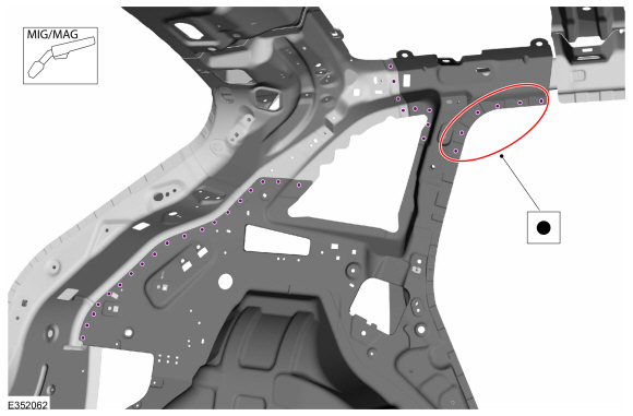
Remove the welds.
Use the General Equipment: Spot Weld Drill Bit
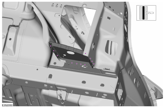 |
-
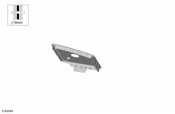
Remove the extension panel.
.jpg) |
-
Remove the welds.
Use the General Equipment: Spot Weld Drill Bit
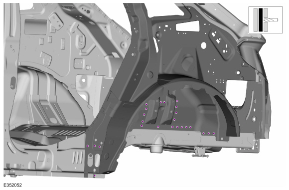 |
-
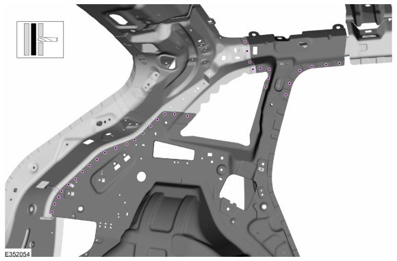
Remove the welds.
Use the General Equipment: Spot Weld Drill Bit
.jpg) |
-
Remove the welds.
Use the General Equipment: Spot Weld Drill Bit
 |
-
Remove the inner quarter panel and wheelhouse.
.jpg) |
Installation
NOTE: Left hand (LH) side shown, right hand (RH) side similar.
NOTE: Factory welds may be substituted with resistance or metal inert gas (MIG) plug welds. Resistance welds may not be placed directly over original location. They must be placed adjacent to original location and match factory welds in quantity. Metal inert gas (MIG) plug welds must equal factory welds in both location and quantity.
NOTE: Adequately protect all adjacent areas against cutting, grinding and welding procedures.
-
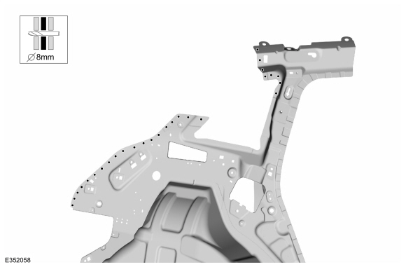
Drill plug welds holes in replacement panel.
Use the General Equipment: 8 mm Drill Bit
.jpg) |
-
Drill plug welds holes in replacement panel.
Use the General Equipment: 8 mm Drill Bit
.jpg) |
-
Drill plug welds holes in replacement panel.
Use the General Equipment: 8 mm Drill Bit
 |
-
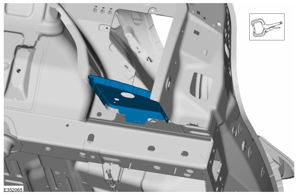
Inatal,properly position and clamp the inner quarter panel and wheelhouse.
Use the General Equipment: Locking Pliers
.jpg) |
-
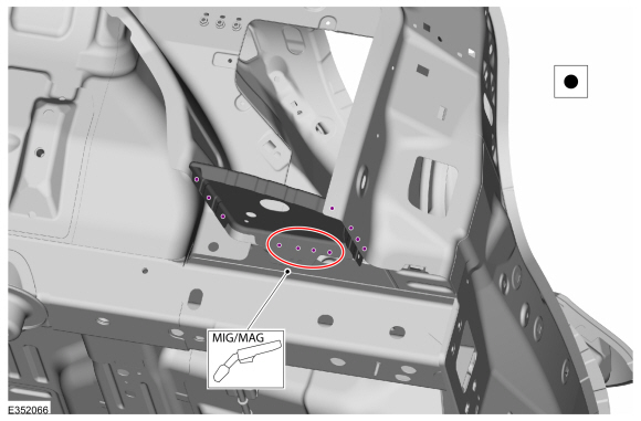
Install the welds.
Use the General Equipment: Resistance Spotwelding Equipment
Use the General Equipment: MIG/MAG Welding Equipment
.jpg) |
-
Install the welds.
Use the General Equipment: Resistance Spotwelding Equipment
Use the General Equipment: MIG/MAG Welding Equipment
.jpg) |
-
Install the welds.
Use the General Equipment: Resistance Spotwelding Equipment
Use the General Equipment: MIG/MAG Welding Equipment
 |
-
Drill plug welds holes in replacement panel.
Use the General Equipment: 8 mm Drill Bit
 |
-
Inatal,properly position and clamp the extension panel.
Use the General Equipment: Locking Pliers
 |
-
Install the welds.
Use the General Equipment: Resistance Spotwelding Equipment
Use the General Equipment: MIG/MAG Welding Equipment
 |
-
Dress all welds as required using typical metal finishing techniques and materials.
-
Sealing work:
All areas must be sealed to production level.
Material: Seam Sealer / TA-2-B, 3M™ 08308, LORD Fusor® 803DTM
-
Refinish the entire repair using a Ford approved paint system.
-
Restore corrosion protection.
Refer to: Corrosion Prevention (501-25 Body Repairs - General Information, General Procedures).
-
Reposition the carpet and wiring harnesses to original location.
-
Install the rocher panel inner reinforcement.
Refer to: Rocker Panel Inner Reinforcement (501-29 Side Panel Sheet Metal Repairs, Removal and Installation).
-
Installthe quarter panel.
Refer to: Quarter Panel LH (501-30 Rear End Sheet Metal Repairs, Removal and Installation).
-
Repower the SRS .
Refer to: Supplemental Restraint System (SRS) Repowering (501-20B Supplemental Restraint System, General Procedures).
 Front Floor Panel Upper Rear Crossmember. Removal and Installation
Special Tool(s) /
General Equipment
8 mm Drill Bit
MIG/MAG Welding Equipment
Spot Weld Drill Bit
Locking Pliers
Materials
Name
Specification
Seam SealerTA-2-B, 3M™ 08308, LORD Fusor® 803DTM
-
Removal
NOTE:
Left hand (LH) side shown, right hand (RH) side similar...
 Quarter Panel LH. Removal and Installation
Special Tool(s) /
General Equipment
Resistance Spotwelding Equipment
Spherical Cutter
Air Body Saw
8 mm Drill Bit
MIG/MAG Welding Equipment
Spot Weld Drill Bit
Locking Pliers
Materials
Name
Specification
Metal Bonding AdhesiveTA-1, TA-1-B, 3M™ 08115, LORD Fusor® 108B, Henkel Teroson EP 5055
-
Flexible Foam Repair3M™ 08463, LORD Fus..
Other information:
Lincoln Nautilus 2018-2026 Service Manual: Roof Opening Panel. Description and Operation
Roof Opening Panel The roof opening panel consists of the following: Air deflector Sliding glass panel Sliding glass panel motor Shield assembly Shield motor Roof opening panel fixed glass Roof opening panel frame assembly Roof opening panel drain hoses Roof opening panel control switch Roof opening panel seal The roof opening panel motor m..
Lincoln Nautilus 2018-2026 Service Manual: Climate Control System - Component Location. Description and Operation
Item Description 1 Driver side register 2 In-vehicle temperature & humidity sensor 3 Sunload sensor 4 Passenger side register 5 HVAC control module 6 Center registers Item Description 1 Heater core 2 Driver side footwell air discharge temperature sensor 3 Evaporator temperature sensor 4 ..
Categories
- Manuals Home
- 1st Generation Nautilus Owners Manual
- 1st Generation Nautilus Service Manual
- Drive Mode Control
- Locating the Pre-Collision Assist Sensors
- Programming the Garage Door Opener to Your Garage Door Opener Motor
- New on site
- Most important about car
USB Ports
Locating the USB Ports
Data Transfer USB Ports

The USB Ports could be in the following locations:
On the lower instrument panel. Inside the media bin. Inside the center console.Note: These USB ports can also charge devices.