Lincoln Nautilus: Front Drive Halfshafts / Front Halfshaft RH - 2.0L EcoBoost (184kW/250PS) – MI4, All-Wheel Drive (AWD). Removal and Installation
Special Tool(s) / General Equipment
 |
204-161
(T97P-1175-A)
Installer, Halfshaft TKIT-1997-LM2 TKIT-1997-F/FM2 TKIT-1997-FLM2 |
 |
205-D070
(D93P-1175-B)
Remover, Front Wheel Hub |
| Tire Lever | |
Removal
-
Remove the wheel and tire.
Refer to: Wheel and Tire (204-04A Wheels and Tires, Removal and Installation).
-
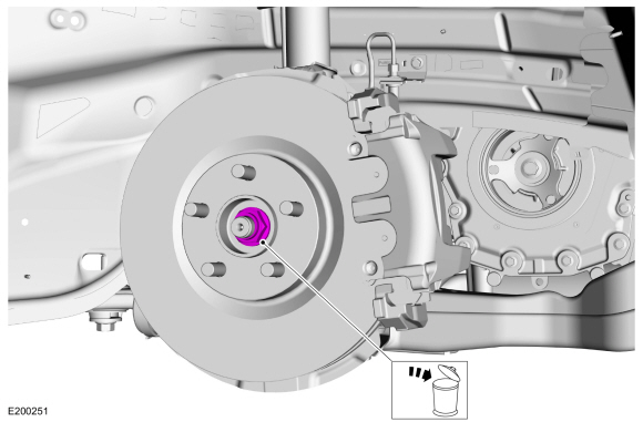
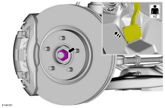
Remove and discard the wheel hub nut.
 |
-
Remove the brake flexible hose bracket bolt and position the brake flexible hose aside.
 |
-
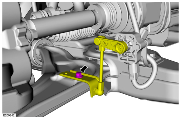
NOTICE: The front suspension height sensor must be disconnected from the lower control arm prior to servicing suspension components or damage to the suspension height sensor and/or the vehicle dynamic suspension system may occur. The sensor will need to be recalibrated after reassembly.
If equipped.
Remove the front height sensor arm bracket bolt and position the front height sensor arm bracket aside.
 |
-
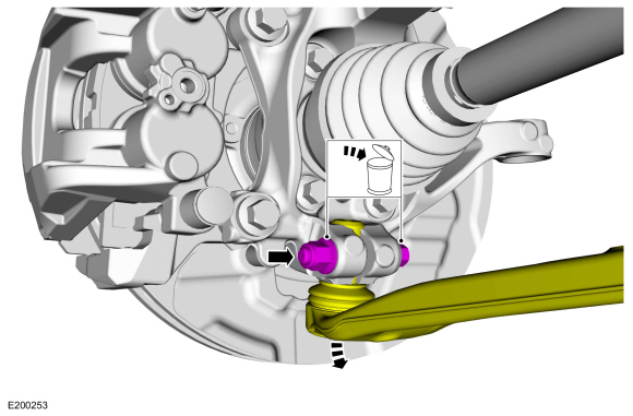
NOTICE: Do not use a prying device or separator fork between the ball joint and the wheel knuckle. Damage to the ball joint or ball joint seal may result. Only use the pry bar by inserting it into the lower arm body opening.
NOTICE: Use care when releasing the lower arm and wheel knuckle into the resting position or damage to the ball joint seal may occur.
Remove and discard the ball joint pinch bolt and nut and separate the ball joint from the wheel knuckle.
 |
-
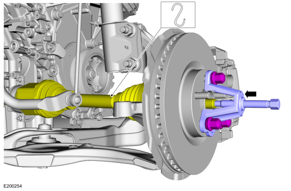
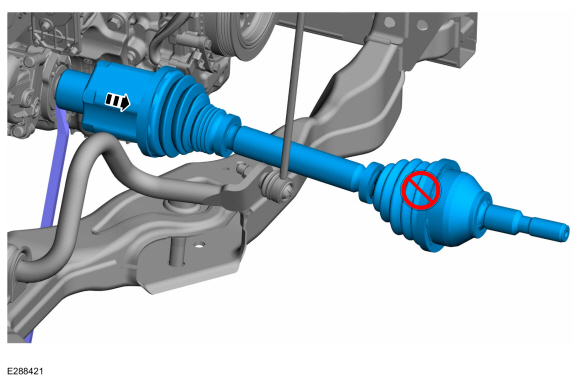
NOTICE: Do not bend the inner joint more than 18 degrees and the outer joint more than 45 degrees. Damage to the shaft will occur.
Install the special tool and press the halfshaft from the front wheel bearing and wheel hub.
Use Special Service Tool: 205-D070 (D93P-1175-B) Remover, Front Wheel Hub.
 |
-
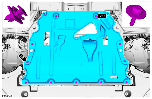
If equipped.
Remove the underbody shield.
 |
-
Remove the halfshaft.
Use the General Equipment: Tire Lever
 |
-
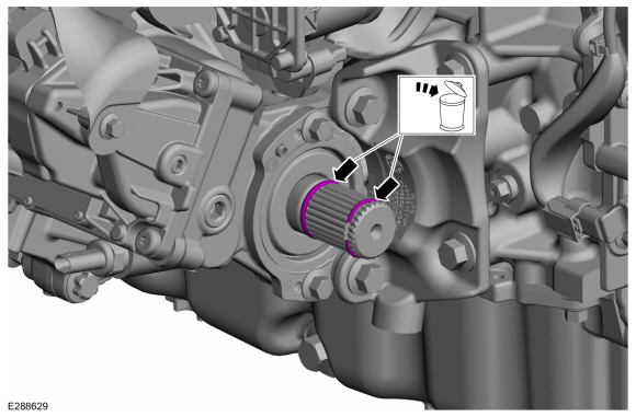
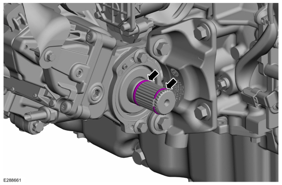
Remove and discard the circlip and O-Ring seal from the intermediate shaft.
 |
Installation
-
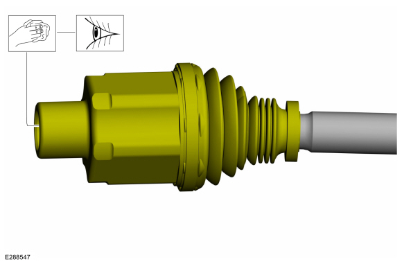
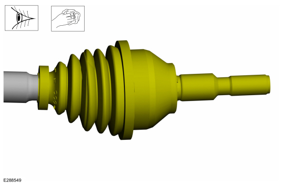
Clean and inspect the inboard end of the halfshaft.
 |
-
Clean and inspect the outboard end of the halfshaft.
 |
-
Install the new circlip and O-Ring seal on the intermediate shaft.
 |
-
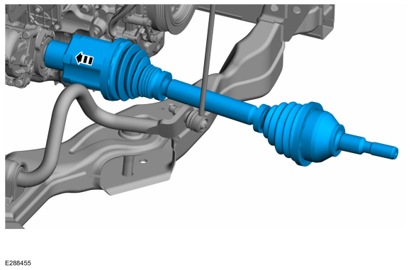
Install the RH halfshaft on the intermediate shaft.
 |
-
-
Insert halfshaft through the wheel bearing.
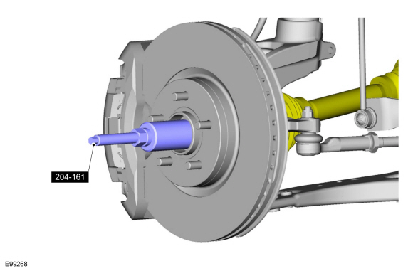
-
Using the special tool, seat the halfshaft splines in the wheel bearing.
Use Special Service Tool: 204-161 (T97P-1175-A) Installer, Halfshaft.
-
Insert halfshaft through the wheel bearing.
 |
-
Position the ball joint into the wheel knuckle and install the new ball joint pinch bolt and nut.
Torque: 76 lb.ft (103 Nm)
 |
-
If equipped.
Position the front height sensor arm bracket and install the front height sensor arm bracket bolt.
Torque: 177 lb.in (20 Nm)
|
-
Position the brake flexible hose and install the brake flexible hose bracket bolt.
Torque: 159 lb.in (18 Nm)
|
-
NOTICE: Do not tighten the front wheel hub nut with the vehicle on the ground. The nut must be tightened to specification before the vehicle is lowered onto the wheels. Wheel bearing damage will occur if the wheel bearing is loaded with the weight of the vehicle applied.
NOTICE: Install and tighten the new wheel hub nut to specification in a continuous rotation. Always install a new wheel hub nut after loosening or when not tightened to specification in a continuous rotation or damage to the components may occur.
NOTE: Apply the brake to keep the halfshaft from rotating.
While an assistant applies the brake, install the new wheel hub nut.
Torque: 148 lb.ft (200 Nm)
 |
-
If equipped.
Install the underbody shield and the retainers.
|
-
Install the wheel and tire.
Refer to: Wheel and Tire (204-04A Wheels and Tires, Removal and Installation).
-
Calibrate the suspension system. Connect the scan tool
and carry out the Ride Height Calibration routine. Follow the scan tool
directions.
 Front Halfshaft RH - FWD. Removal and Installation
Special Tool(s) /
General Equipment
204-161
(T97P-1175-A)
Installer, HalfshaftTKIT-1997-LM2TKIT-1997-F/FM2TKIT-1997-FLM2
205-D070
(D93P-1175-B)
Remover, Front Wheel Hub
Removal
Remove the wheel and tire...
 Front Halfshaft RH - 2.7L EcoBoost (238kW/324PS), All-Wheel Drive (AWD). Removal and Installation
Special Tool(s) /
General Equipment
204-161
(T97P-1175-A)
Installer, HalfshaftTKIT-1997-LM2TKIT-1997-F/FM2TKIT-1997-FLM2
205-D070
(D93P-1175-B)
Remover, Front Wheel Hub
Removal
Remove the wheel and tire...
Other information:
Lincoln Nautilus 2018-2026 Service Manual: Handles, Locks, Latches and Entry Systems - System Operation and Component Description. Description and Operation
System Operation System Diagram NOTE: The Phone As A Key feature can also be used to lock/unlock the vehicle. Refer to section 419-01C for information regarding this feature. *.sttxt { visibility: hidden; } *.stcallout { visibility: visible; } ..
Lincoln Nautilus 2018-2026 Service Manual: Fender Apron Panel. Removal and Installation
Special Tool(s) / General Equipment Resistance Spotwelding Equipment Scraper for Straight Edges Hot Air Gun 8 mm Drill Bit MIG/MAG Welding Equipment Spot Weld Drill Bit Locking Pliers Materials Name Specification Seam SealerTA-2-B, 3M™ 08308, LORD Fusor® 803DTM - Removal NOTE: LH side shown, RH side similar. NOTE: Factory ..
Categories
- Manuals Home
- 1st Generation Nautilus Owners Manual
- 1st Generation Nautilus Service Manual
- Massage Seats
- Engine Oil Capacity and Specification - 2.0L
- Power Outlet - Vehicles With: 110V Power Outlet
- New on site
- Most important about car
Locating the Pre-Collision Assist Sensors

If a message regarding a blocked sensor or camera appears in the information display, something is obstructing the radar signals or camera images. The radar sensor is behind the fascia cover in the center of the lower grille. With a blocked sensor or camera, the system may not function, or performance may reduce. See Pre-Collision Assist – Information Messages.