Lincoln Nautilus: Front Seats / Front Seat Cushion Cover. Removal and Installation
Removal
 WARNING:
The following procedure prescribes critical repair steps
required for correct restraint system operation during a crash. Follow
all notes and steps carefully. Failure to follow step instructions may
result in incorrect operation of the restraint system and increases the
risk of serious personal injury or death in a crash.
WARNING:
The following procedure prescribes critical repair steps
required for correct restraint system operation during a crash. Follow
all notes and steps carefully. Failure to follow step instructions may
result in incorrect operation of the restraint system and increases the
risk of serious personal injury or death in a crash.
NOTICE: To prevent system failure, carry out the OCS reset when a front passenger seat cushion is disassembled, a new trim cover is installed or an OCS service kit is installed. Use a diagnostic scan tool to carry out the OCS reset command.
NOTICE: The cushion heater mat on a front outboard passenger seat is not serviced separately. If a new cushion heater mat is needed on the front passenger seat, install an OCS service kit equipped with a heater mat. Failure to follow this instruction may result in incorrect operation of the OCS .
NOTE: The OCS components (seat cushion foam, heater mat (if equipped) and OCS ) are calibrated to each other and are serviced as an assembly. The OCS components are not to be installed separately. If a new OCS , seat cushion foam or heater mat (if equipped) are needed, a new OCS service kit must be installed.
NOTE: Driver seat shown, passenger seat similar.
NOTE: Removal steps in this procedure may contain installation details.
All seats
-
NOTE: For the passenger seat, follow the unique instructions or graphic for this step in the installation.
Remove the front seat.
Refer to: Front Seat (501-10A Front Seats, Removal and Installation).
-
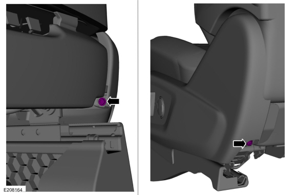
Remove the side shield screws.
 |
-
Remove the side shield.
-
Lift up on the rear of the side shield and pull outward.
-
Push the side shield forward.
-
Disconnect the electrical connector.
-
Lift up on the rear of the side shield and pull outward.
 |
-
Detach the electrical connector retainers and position the wiring harnesses aside.
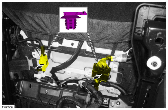 |
-
-
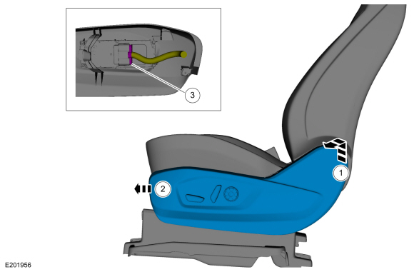
Detach the backrest cover straps.
-
Position the backrest cover upward.
-
Detach the backrest cover straps.
 |
-
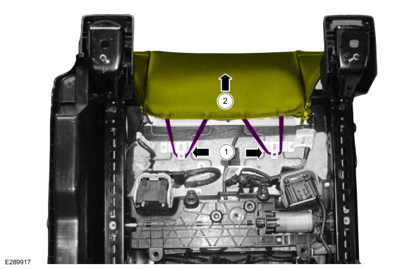
Detach the cushion cover J-clips and position the cushion cover upward.
 |
-
Disconnect the cushion heater mat electrical connector and detach the harness locator.
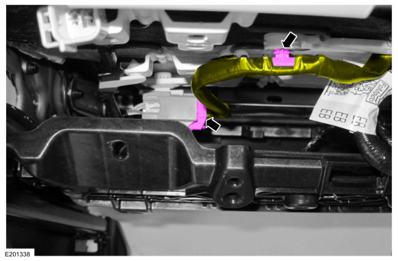 |
-
If equipped.
Remove the screws, disconnect the electrical connectors and remove the DSM .
Torque: 19 lb.in (2.1 Nm)
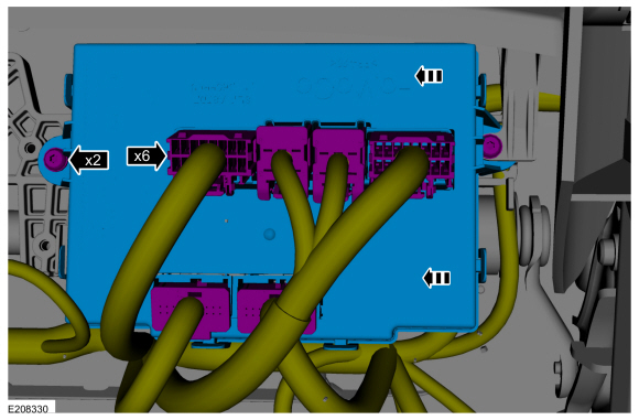 |
-
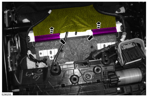
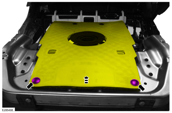
Detach the seat cushion cover J-clips.
-
On both sides.
Detach the cushion cover side J-clips.
-
Detach the cushion cover front J-clip.
-
On both sides.
.jpg) |
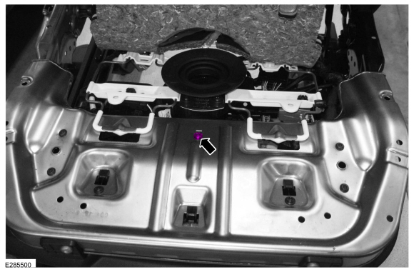
Passenger seat
-
Lift the cushion foam. If the cushion foam and OCS are adhered
together, then the OCS is a service kit. If nothing is adhered together,
then the OCS is original equipment.
 |
Driver seat or passenger seat without OCS service kit
-
Remove the seat cushion cover and foam as an assembly.
.jpg) |
Passenger seat with OCS service kit
-
Disconnect the OCS sensor.
.jpg) |
-
NOTE: Original equipment OCS shown, service kit similar.
Remove the pin-type retainers and raise the front of the OCS bladder.
 |
-
Remove the OCS bracket screw.
Torque: 44 lb.in (5 Nm)
 |
-
NOTE: Note the location of the OCS hose and heater mat pigtail (if equipped) as it passes through the seat cushion support for proper installation.
Route out the OCS hose, sensor, sensor bracket and heater mat wiring pigtail (if equipped) from between the seat cushion support wires and remove the OCS .
.jpg) |
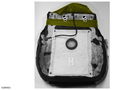
All seats
-
Invert the rear portion of the seat cushion cover from the foam.
 |
-
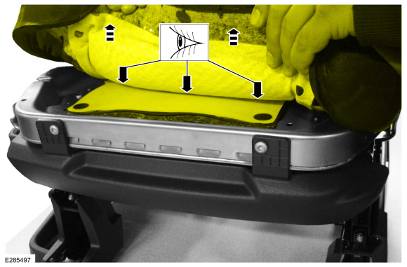
NOTICE: Use care when separating the seat cushion trim cover from the hook-and-loop strips or the hook-and-loop strips may be torn from the seat cushion foam.
NOTICE: Use care when separating the seat cushion from the hook-and-arrow or the hook may be torn from the seat cushion foam.
NOTE: This step is only necessary when installing a new component.
Remove the seat cushion cover.
-
Invert the seat cushion cover.
-
Release the hook-and-arrows.
-
Release the hook-and-loops.
-
Invert the seat cushion cover.
.jpg) |
Installation
All seats
-
NOTICE: Inspect the OCS bladder, seat cushion pan and support assembly for any foreign objects before installing the OCS to the seat cushion pan. Remove any foreign objects. Failure to follow these instructions may result in incorrect operation of the OCS and may cause system failure.
NOTICE: Do not trap the pressure sensor hose incorrectly over the seat's suspension or spring. Route the hose so that it lays in a natural bend, and is not twisted due to being forced into an unnatural position. Failure to follow these instructions may result in component damage and/or system failure.
To install, reverse the removal procedure.
-
Install the front seat. If the passenger seat has been serviced, do not prove out the
SRS
at this time.
Refer to: Front Seat (501-10A Front Seats, Removal and Installation).
Passenger seat
-
WARNING:
Occupant Classification System (OCS) parts are
calibrated as an assembly and must only be replaced in the configuration
they are sold. Never separate parts of an assembly. Failure to follow
this instruction may result in incorrect operation of the OCS and
increases the risk of serious personal injury or death in a crash.
WARNING:
Make sure the front passenger seat repair is
complete, the seat and all attached components (head restraint, seat
side shield, etc.) are correctly assembled, and the seat is correctly
installed to the vehicle before using System Reset to rezero the seat
weight. Failure to follow these instructions may result in incorrect
operation of the occupant classification system (OCS) and increases the
risk of serious personal injury or death in a crash.
NOTICE: To prevent system failure, take the following precautions before carrying out the OCS reset.
- Make sure the voltage to the OCSM is greater than 8 volts and less than 18 volts.
- Make sure the OCS is not below 6º C (42.8º F) or above 36º C (96.7º F) when initiating the OCS reset process. If the vehicle has been exposed to extreme cold or hot temperatures, the vehicle must be exposed and kept at a temperature between 6º C (42.8º F) to 36º C (96.7º F) for a minimum of 30 minutes.
- Make sure nothing is present on the passenger seat before and during the OCS reset process.
- Prior to carrying out the OCS reset, make sure a minimum of 8 seconds has elapsed after cycling the ignition switch on.
-
If the first system reset attempt was successful, proceed to prove out the SRS .
-
If the first system reset attempt was not successful, carry out a thorough visual inspection of the OCS
connector and wiring for damage, pressure sensor hose for kinks and or
damage, and seat-related wiring harness and body wiring harness
terminals and connectors for damage. Repair any concerns found and
proceed to the next step.
-
Carry out a second OCS reset. Cycle the ignition switch after the OCS
reset. If the second attempt is unsuccessful, install a new OCS service
kit.
Refer to: Occupant Classification System (OCS) Sensor (501-20 Supplemental Restraint System) .
-
Prove out the SRS
. Verify all airbags are installed and connected and the ignition is
OFF. Wait 10 seconds then turn the ignition ON and monitor the airbag
warning indicator. The airbag warning indicator illuminates continuously
for approximately 6 seconds and turns off. Continue to monitor the
airbag warning indicator for approximately 30 seconds, as this is the
time required for the RCM to complete testing of the SRS .
-
-
If a SRS
fault is present, the airbag warning indicator either fails to light,
remains lit continuously or flashes. The flashing may not occur until
approximately 30 seconds after the ignition has been turned from OFF to
ON. If this occurs, diagnose and repair any SRS faults before proceeding with other repairs.
-
If, after the ignition has been turned on for 30
seconds, the airbag warning indicator remains unlit with no chime or
SRS message displayed in the message center, no SRS fault is present.
-
If the airbag warning indicator is inoperative and a SRS
fault exists, a chime sounds in a pattern of 5 sets of 5 beeps or a
message displays in the message center. If this occurs, diagnose and
repair the airbag warning indicator and any SRS faults before proceeding with other repairs.
-
If a SRS
fault is present, the airbag warning indicator either fails to light,
remains lit continuously or flashes. The flashing may not occur until
approximately 30 seconds after the ignition has been turned from OFF to
ON. If this occurs, diagnose and repair any SRS faults before proceeding with other repairs.
-
Using a diagnostic scan tool, clear all Continuous
Memory Diagnostic Trouble Codes (CMDTCs) from all modules.
 Front Seat Cushion Blower Motor. Removal and Installation
Removal
Remove the front seat cushion cover and foam as an assembly.
Refer to: Front Seat Cushion Cover (501-10A Front Seats, Removal and Installation)...
 Front Seat Power Lumbar Assembly. Removal and Installation
Removal
NOTE:
Driver seat shown, passenger seat similar.
Remove the front seat.
Refer to: Front Seat (501-10A Front Seats, Removal and Installation)...
Other information:
Lincoln Nautilus 2018-2026 Service Manual: Module Configuration. Diagnosis and Testing
Diagnostic Trouble Code (DTC) Chart Diagnostics in this manual assume a certain skill level and knowledge of Ford-specific diagnostic practices.REFER to: Diagnostic Methods (100-00 General Information, Description and Operation). Module DTC Description Action BCM U1023:00 Vehicle Inhibited Due To Cloud Control: No Sub Type Information GO to Pinpoint Test C GWM U102D:00 In..
Lincoln Nautilus 2018-2026 Service Manual: Evaporator Core Leak Check. General Procedures
Inspection Recover the refrigerant. Refer to: Air Conditioning (A/C) System Recovery, Evacuation and Charging (412-00 Climate Control System - General Information, General Procedures). Disconnect the evaporator from the A/C system. Refer to the appropriate removal and installation section in Group 412 for the procedure. Use the correct adapters with the A/C Serv..
Categories
- Manuals Home
- 1st Generation Nautilus Owners Manual
- 1st Generation Nautilus Service Manual
- Changing the 12V Battery
- Normal Scheduled Maintenance
- Massage Seats
- New on site
- Most important about car
Traction Control
How Does Traction Control Work
If your vehicle begins to slide, the system applies the brakes to individual wheels and, when needed, reduces power at the same time. If the wheels spin when accelerating on slippery or loose surfaces, the system reduces power in order to increase traction.
Switching Traction Control On and Off
WARNING: The stability and traction control light illuminates steadily if the system detects a failure. Make sure you did not manually disable the traction control system using the information display controls or the switch. If the stability control and traction control light is still illuminating steadily, have the system serviced by an authorized dealer immediately. Operating your vehicle with the traction co