Lincoln Nautilus: Front Seats / Front Seats. Diagnosis and Testing
DTC Chart: DDM
Diagnostics in this manual assume a certain skill level and knowledge of Ford-specific diagnostic practices.
REFER to: Diagnostic Methods (100-00 General Information, Description and Operation).
DDM
DTC Chart
|
DTC
|
Description
|
Action
|
|
B1C03:23
|
Memory #1 Switch: Signal Stuck Low
|
GO to Pinpoint Test H
|
|
B1C04:23
|
Memory #2 Switch: Signal Stuck Low
|
GO to Pinpoint Test H
|
|
B1C05:23
|
Memory #3 Switch: Signal Stuck Low
|
GO to Pinpoint Test H
|
|
All other Diagnostic Trouble Codes (DTCs)
|
-
|
REFER to: Locks, Latches and Entry Systems (501-14 Handles, Locks, Latches and Entry Systems, Diagnosis and Testing).
|
DTC Chart: DSM
Diagnostics in this manual assume a certain skill level and knowledge of Ford-specific diagnostic practices.
REFER to: Diagnostic Methods (100-00 General Information, Description and Operation).
DSM
DTC Chart
|
DTC
|
Description
|
Action
|
|
B1060:09
|
Seat Headrest Motor Output: Component Failure
|
GO to Pinpoint Test G
|
|
B1060:11
|
Seat Headrest Motor Output: Circuit Short To Ground
|
GO to Pinpoint Test G
|
|
B1060:12
|
Seat Headrest Motor Output: Circuit Short To Battery
|
GO to Pinpoint Test G
|
|
B1060:13
|
Seat Headrest Motor Output: Circuit Open
|
GO to Pinpoint Test G
|
|
B1060:1A
|
Seat Headrest Motor Output: Circuit Resistance Below Threshold
|
GO to Pinpoint Test G
|
|
B1060:31
|
Seat Headrest Motor Output: No Signal
|
GO to Pinpoint Test H
|
|
B106D:24
|
Headrest Up Switch: Signal Stuck High
|
GO to Pinpoint Test G
|
|
B106E:24
|
Headrest Down Switch: Signal Stuck High
|
GO to Pinpoint Test G
|
|
B1168:11
|
Seat Headrest Motor Speed/Position Sensor: Circuit Short To Ground
|
GO to Pinpoint Test H
|
|
B1168:12
|
Seat Headrest Motor Speed/Position Sensor: Circuit Short To Battery
|
GO to Pinpoint Test H
|
|
B14C3:24
|
Seat Height Rear Down Switch: Signal Stuck High
|
-
For 10-way seat, GO to Pinpoint Test F
-
For 16-way seat, GO to Pinpoint Test G
|
|
B14C4:24
|
Seat Height Rear Up Switch: Signal Stuck High
|
-
For 10-way seat, GO to Pinpoint Test F
-
For 16-way seat, GO to Pinpoint Test G
|
|
B14C5:24
|
Seat Headrest Forward Switch: Signal Stuck High
|
GO to Pinpoint Test G
|
|
B14C6:24
|
Seat Headrest Rearward Switch: Signal Stuck High
|
GO to Pinpoint Test G
|
|
B14CB:11
|
Seat Height Rear Position Feedback: Circuit Short To Ground
|
GO to Pinpoint Test H
|
|
B14CB:12
|
Seat Height Rear Position Feedback: Circuit Short To Battery
|
GO to Pinpoint Test H
|
|
B14CD:11
|
Seat Head Restraint Forward/Rearward Position Feedback: Circuit Short To Ground
|
GO to Pinpoint Test H
|
|
B14CD:12
|
Seat Head Restraint Forward/Rearward Position Feedback: Circuit Short To Battery
|
GO to Pinpoint Test H
|
|
B14CE:09
|
Seat Horizontal Motor Output: Component Failure
|
-
For 10-way seat, GO to Pinpoint Test F
-
For 16-way seat, GO to Pinpoint Test G
|
|
B14CE:11
|
Seat Horizontal Motor Output: Circuit Short To Ground
|
-
For 10-way seat, GO to Pinpoint Test F
-
For 16-way seat, GO to Pinpoint Test G
|
|
B14CE:12
|
Seat Horizontal Motor Output: Circuit Short To Battery
|
-
For 10-way seat, GO to Pinpoint Test F
-
For 16-way seat, GO to Pinpoint Test G
|
|
B14CE:14
|
Seat Horizontal Motor Output: Circuit Short To Ground or Open
|
-
For 10-way seat, GO to Pinpoint Test F
-
For 16-way seat, GO to Pinpoint Test G
|
|
B14CE:15
|
Seat Horizontal Motor Output: Circuit Short To Battery or Open
|
-
For 10-way seat, GO to Pinpoint Test F
-
For 16-way seat, GO to Pinpoint Test G
|
|
B14CE:1A
|
Seat Horizontal Motor Output: Circuit Resistance Below Threshold
|
-
For 10-way seat, GO to Pinpoint Test F
-
For 16-way seat, GO to Pinpoint Test G
|
|
B14CE:31
|
Seat Horizontal Motor Output: No Signal
|
GO to Pinpoint Test H
|
|
B14CF:09
|
Seat Recline Motor Output: Component Failure
|
-
For 10-way seat, GO to Pinpoint Test F
-
For 16-way seat, GO to Pinpoint Test G
|
|
B14CF:11
|
Seat Recline Motor Output: Circuit Short To Ground
|
-
For 10-way seat, GO to Pinpoint Test F
-
For 16-way seat, GO to Pinpoint Test G
|
|
B14CF:12
|
Seat Recline Motor Output: Circuit Short To Battery
|
-
For 10-way seat, GO to Pinpoint Test F
-
For 16-way seat, GO to Pinpoint Test G
|
|
B14CF:14
|
Seat Recline Motor Output: Circuit Short To Ground or Open
|
-
For 10-way seat, GO to Pinpoint Test F
-
For 16-way seat, GO to Pinpoint Test G
|
|
B14CF:15
|
Seat Recline Motor Output: Circuit Short To Battery or Open
|
-
For 10-way seat, GO to Pinpoint Test F
-
For 16-way seat, GO to Pinpoint Test G
|
|
B14CF:1A
|
Seat Recline Motor Output: Circuit Resistance Below Threshold
|
-
For 10-way seat, GO to Pinpoint Test F
-
For 16-way seat, GO to Pinpoint Test G
|
|
B14CF:31
|
Seat Recline Motor Output: No Signal
|
GO to Pinpoint Test H
|
|
B14D0:09
|
Seat Height Front/Tilt Motor Output: Component Failure
|
-
For 10-way seat, GO to Pinpoint Test F
-
For 16-way seat, GO to Pinpoint Test G
|
|
B14D0:11
|
Seat Height Front/Tilt Motor Output: Circuit Short To Ground
|
-
For 10-way seat, GO to Pinpoint Test F
-
For 16-way seat, GO to Pinpoint Test G
|
|
B14D0:12
|
Seat Height Front/Tilt Motor Output: Circuit Short To Battery
|
-
For 10-way seat, GO to Pinpoint Test F
-
For 16-way seat, GO to Pinpoint Test G
|
|
B14D0:14
|
Seat Height Front/Tilt Motor Output: Circuit Short To Ground or Open
|
-
For 10-way seat, GO to Pinpoint Test F
-
For 16-way seat, GO to Pinpoint Test G
|
|
B14D0:15
|
Seat Height Front/Tilt Motor Output: Circuit Short To Battery or Open
|
-
For 10-way seat, GO to Pinpoint Test F
-
For 16-way seat, GO to Pinpoint Test G
|
|
B14D0:1A
|
Seat Height Front/Tilt Motor Output: Circuit Resistance Below Threshold
|
-
For 10-way seat, GO to Pinpoint Test F
-
For 16-way seat, GO to Pinpoint Test G
|
|
B14D0:31
|
Seat Height Front/Tilt Motor Output: No Signal
|
GO to Pinpoint Test H
|
|
B14D1:09
|
Seat Head Restraint Forward/Rearward Motor Output: Component Failure
|
GO to Pinpoint Test G
|
|
B14D1:11
|
Seat Head Restraint Forward/Rearward Motor Output: Circuit Short To Ground
|
GO to Pinpoint Test G
|
|
B14D1:12
|
Seat Head Restraint Forward/Rearward Motor Output: Circuit Short To Battery
|
GO to Pinpoint Test G
|
|
B14D1:13
|
Seat Head Restraint Forward/Rearward Motor Output: Circuit Open
|
GO to Pinpoint Test G
|
|
B14D1:1A
|
Seat Head Restraint Forward/Rearward Motor Output: Circuit Resistance Below Threshold
|
GO to Pinpoint Test G
|
|
B14D1:31
|
Seat Head Restraint Forward/Rearward Motor Output: No Signal
|
GO to Pinpoint Test H
|
|
B14D2:09
|
Seat Height Rear Motor Output: Component Failure
|
-
For 10-way seat, GO to Pinpoint Test F
-
For 16-way seat, GO to Pinpoint Test G
|
|
B14D2:11
|
Seat Height Rear Motor Output: Circuit Short To Ground
|
-
For 10-way seat, GO to Pinpoint Test F
-
For 16-way seat, GO to Pinpoint Test G
|
|
B14D2:12
|
Seat Height Rear Motor Output: Circuit Short To Battery
|
-
For 10-way seat, GO to Pinpoint Test F
-
For 16-way seat, GO to Pinpoint Test G
|
|
B14D2:14
|
Seat Height Rear Motor Output: Circuit Short To Ground or Open
|
-
For 10-way seat, GO to Pinpoint Test F
-
For 16-way seat, GO to Pinpoint Test G
|
|
B14D2:15
|
Seat Height Rear Motor Output: Circuit Short To Battery or Open
|
-
For 10-way seat, GO to Pinpoint Test F
-
For 16-way seat, GO to Pinpoint Test G
|
|
B14D2:1A
|
Seat Height Rear Motor Output: Circuit Resistance Below Threshold
|
-
For 10-way seat, GO to Pinpoint Test F
-
For 16-way seat, GO to Pinpoint Test G
|
|
B14D2:31
|
Seat Height Rear Motor Output: No Signal
|
GO to Pinpoint Test H
|
|
B151F:09
|
Left Cushion Motor Output: Component Failure
|
GO to Pinpoint Test G
|
|
B151F:11
|
Left Cushion Motor Output: Circuit Short To Ground
|
GO to Pinpoint Test G
|
|
B151F:12
|
Left Cushion Motor Output: Circuit Short To Battery
|
GO to Pinpoint Test G
|
|
B151F:13
|
Left Cushion Motor Output: Circuit Open
|
GO to Pinpoint Test G
|
|
B151F:1A
|
Left Cushion Motor Output: Circuit Resistance Below Threshold
|
GO to Pinpoint Test G
|
|
B151F:31
|
Left Cushion Motor Output: No Signal
|
GO to Pinpoint Test H
|
|
B1523:11
|
Left Cushion Motor Position Sensor Feedback: Circuit Short To Ground
|
GO to Pinpoint Test H
|
|
B1523:12
|
Left Cushion Motor Position Sensor Feedback: Circuit Short To Battery
|
GO to Pinpoint Test H
|
|
B1527:24
|
Left Cushion Fore Switch: Signal Stuck High
|
GO to Pinpoint Test G
|
|
B1527:24
|
Left Cushion Aft Switch: Signal Stuck High
|
GO to Pinpoint Test G
|
|
B1B89:11
|
Seat Slide Motor Speed/Position Sensor: Circuit Short To Ground
|
GO to Pinpoint Test H
|
|
B1B89:12
|
Seat Slide Motor Speed/Position Sensor: Circuit Short To Battery
|
GO to Pinpoint Test H
|
|
B1B91:11
|
Seat Tilt Motor Speed/Position Sensor: Circuit Short To Ground
|
GO to Pinpoint Test H
|
|
B1B91:12
|
Seat Tilt Motor Speed/Position Sensor: Circuit Short To Battery
|
GO to Pinpoint Test H
|
|
B1B93:11
|
Seat Recline Motor Speed/Position Sensor: Circuit Short To Ground
|
GO to Pinpoint Test H
|
|
B1B93:12
|
Seat Recline Motor Speed/Position Sensor: Circuit Short To Battery
|
GO to Pinpoint Test H
|
|
B1B96:24
|
Seat Slide Forward Switch: Signal Stuck High
|
-
For 10-way seat, GO to Pinpoint Test F
-
For 16-way seat, GO to Pinpoint Test G
|
|
B1B97:24
|
Seat Slide Backward Switch: Signal Stuck High
|
-
For 10-way seat, GO to Pinpoint Test F
-
For 16-way seat, GO to Pinpoint Test G
|
|
B1B98:24
|
Seat Tilt Up Switch: Signal Stuck High
|
-
For 10-way seat, GO to Pinpoint Test F
-
For 16-way seat, GO to Pinpoint Test G
|
|
B1B99:24
|
Seat Tilt Down Switch: Signal Stuck High
|
-
For 10-way seat, GO to Pinpoint Test F
-
For 16-way seat, GO to Pinpoint Test G
|
|
B1C00:24
|
Seat Recline Up Switch: Signal Stuck High
|
-
For 10-way seat, GO to Pinpoint Test F
-
For 16-way seat, GO to Pinpoint Test G
|
|
B1C01:24
|
Seat Recline Down Switch: Signal Stuck High
|
-
For 10-way seat, GO to Pinpoint Test F
-
For 16-way seat, GO to Pinpoint Test G
|
|
U0100:00
|
Lost Communication with ECM/PCM "A": No Sub Type Information
|
GO to Pinpoint Test V
|
|
U0140:00
|
Lost Communication with Body Control Module: No Sub Type Information
|
GO to Pinpoint Test S
|
|
U0212:00
|
Lost Communication with Steering Column Control Module: No Sub Type Information
|
GO to Pinpoint Test Y
|
|
U0253:87
|
Lost Communication with Accessory Protocol Interface Module: Missing Message
|
GO to Pinpoint Test AD
GO to Pinpoint Test Z
|
|
U1000:00
|
Solid State Driver Protection Active -Driver Disabled: No Sub Type Information
|
DIAGNOSE any other related DSM Diagnostic Trouble Codes (DTCs) first.
CLEAR the Diagnostic Trouble Codes (DTCs). REPEAT the self-test. If DTC
U1000:00 returns, INSTALL a new DSM .
REFER to: Driver Front Seat Module (DSM) (501-10A Front Seats, Removal and Installation).
|
|
U2100:00
|
Initial Configuration Not Complete: No Sub Type Information
|
NOTE:
This DTC indicates PMI has not been carried out on a newly installed
module or configuration data has been lost. Presence of this DTC alone
does not prevent basic seat operation from the seat control switch.
Using a diagnostic scan tool, CARRY OUT PMI on the DSM . REPEAT the
self-test and VERIFY successful PMI . CLEAR the Diagnostic Trouble Codes
(DTCs).
|
|
U3000:49
|
Control Module: Internal Electronic Failure
|
INSTALL a new DSM .
REFER to: Driver Front Seat Module (DSM) (501-10A Front Seats, Removal and Installation).
|
DTC Chart: HVAC Module
Diagnostics in this manual assume a certain skill level and knowledge of Ford-specific diagnostic practices.
REFER to: Diagnostic Methods (100-00 General Information, Description and Operation).
HVAC Module DTC Chart
|
DTC
|
Description
|
Action
|
|
B1034:11
|
Left Front Seat Heater Element: Circuit Short To Ground
|
GO to Pinpoint Test K
|
|
B1034:15
|
Left Front Seat Heater Element: Circuit Short To Battery or Open
|
GO to Pinpoint Test K
|
|
B1036:11
|
Right Front Seat Heater Element: Circuit Short To Ground
|
GO to Pinpoint Test L
|
|
B1036:15
|
Right Front Seat Heater Element: Circuit Short To Battery or Open
|
GO to Pinpoint Test L
|
|
B1038:11
|
Left Front Seat Heater Sensor: Circuit Short To Ground
|
GO to Pinpoint Test K
|
|
B1038:15
|
Left Front Seat Heater Sensor: Circuit Short To Battery or Open
|
GO to Pinpoint Test K
|
|
B103A:11
|
Right Front Seat Heater Sensor: Circuit Short To Ground
|
GO to Pinpoint Test L
|
|
B103A:15
|
Right Front Seat Heater Sensor: Circuit Short To Battery or Open
|
GO to Pinpoint Test L
|
|
All other Diagnostic Trouble Codes (DTCs)
|
-
|
Refer to the appropriate section in Group 412 for the procedure.
|
DTC Chart: SCMB
Diagnostics in this manual assume a certain skill level and knowledge of Ford-specific diagnostic practices.
REFER to: Diagnostic Methods (100-00 General Information, Description and Operation).
SCMB
DTC Chart
|
DTC
|
Description
|
Action
|
|
B105F:09
|
Seat Cushion Extension Motor Output: Component Failure
|
GO to Pinpoint Test B
|
|
B105F:11
|
Seat Cushion Extension Motor Output: Circuit Short To Ground
|
GO to Pinpoint Test B
|
|
B105F:12
|
Seat Cushion Extension Motor Output: Circuit Short To Battery
|
GO to Pinpoint Test B
|
|
B105F:13
|
Seat Cushion Extension Motor Output: Circuit Open
|
GO to Pinpoint Test B
|
|
B105F:1A
|
Seat Cushion Extension Motor Output: Circuit Resistance Below Threshold
|
GO to Pinpoint Test B
|
|
B105F:31
|
Seat Cushion Extension Motor Output: No Signal
|
GO to Pinpoint Test C
|
|
B1060:09
|
Seat Headrest Motor Output: Component Failure
|
GO to Pinpoint Test B
|
|
B1060:11
|
Seat Headrest Motor Output: Circuit Short To Ground
|
GO to Pinpoint Test B
|
|
B1060:12
|
Seat Headrest Motor Output: Circuit Short To Battery
|
GO to Pinpoint Test B
|
|
B1060:13
|
Seat Headrest Motor Output: Circuit Open
|
GO to Pinpoint Test B
|
|
B1060:1A
|
Seat Headrest Motor Output: Circuit Resistance Below Threshold
|
GO to Pinpoint Test B
|
|
B1060:31
|
Seat Headrest Motor Output: No Signal
|
GO to Pinpoint Test C
|
|
B1065:24
|
Cushion Extend Switch: Signal Stuck High
|
GO to Pinpoint Test B
|
|
B1066:24
|
Cushion Retract Switch: Signal Stuck High
|
GO to Pinpoint Test B
|
|
B106D:24
|
Headrest Up Switch: Signal Stuck High
|
GO to Pinpoint Test B
|
|
B106E:24
|
Headrest Down Switch: Signal Stuck High
|
GO to Pinpoint Test B
|
|
B14C3:24
|
Seat Height Rear Down Switch: Signal Stuck High
|
GO to Pinpoint Test B
|
|
B14C4:24
|
Seat Height Rear Up Switch: Signal Stuck High
|
GO to Pinpoint Test B
|
|
B14C5:24
|
Seat Headrest Forward Switch: Signal Stuck High
|
GO to Pinpoint Test B
|
|
B14C6:24
|
Seat Headrest Rearward Switch: Signal Stuck High
|
GO to Pinpoint Test B
|
|
B14CE:09
|
Seat Horizontal Motor Output: Component Failure
|
GO to Pinpoint Test B
|
|
B14CE:11
|
Seat Horizontal Motor Output: Circuit Short To Ground
|
GO to Pinpoint Test B
|
|
B14CE:12
|
Seat Horizontal Motor Output: Circuit Short To Battery
|
GO to Pinpoint Test B
|
|
B14CE:14
|
Seat Horizontal Motor Output: Circuit Short To Ground or Open
|
GO to Pinpoint Test B
|
|
B14CE:15
|
Seat Horizontal Motor Output: Circuit Short To Battery or Open
|
GO to Pinpoint Test B
|
|
B14CE:1A
|
Seat Horizontal Motor Output: Circuit Resistance Below Threshold
|
GO to Pinpoint Test B
|
|
B14CE:31
|
Seat Horizontal Motor Output: No Signal
|
GO to Pinpoint Test C
|
|
B14CF:09
|
Seat Recline Motor Output: Component Failure
|
GO to Pinpoint Test B
|
|
B14CF:11
|
Seat Recline Motor Output: Circuit Short To Ground
|
GO to Pinpoint Test B
|
|
B14CF:12
|
Seat Recline Motor Output: Circuit Short To Battery
|
GO to Pinpoint Test B
|
|
B14CF:14
|
Seat Recline Motor Output: Circuit Short To Ground or Open
|
GO to Pinpoint Test B
|
|
B14CF:15
|
Seat Recline Motor Output: Circuit Short To Battery or Open
|
GO to Pinpoint Test B
|
|
B14CF:1A
|
Seat Recline Motor Output: Circuit Resistance Below Threshold
|
GO to Pinpoint Test B
|
|
B14CF:31
|
Seat Recline Motor Output: No Signal
|
GO to Pinpoint Test C
|
|
B14D0:09
|
Seat Height Front/Tilt Motor Output: Component Failure
|
GO to Pinpoint Test B
|
|
B14D0:11
|
Seat Height Front/Tilt Motor Output: Circuit Short To Ground
|
GO to Pinpoint Test B
|
|
B14D0:12
|
Seat Height Front/Tilt Motor Output: Circuit Short To Battery
|
GO to Pinpoint Test B
|
|
B14D0:14
|
Seat Height Front/Tilt Motor Output: Circuit Short To Ground or Open
|
GO to Pinpoint Test B
|
|
B14D0:15
|
Seat Height Front/Tilt Motor Output: Circuit Short To Battery or Open
|
GO to Pinpoint Test B
|
|
B14D0:1A
|
Seat Height Front/Tilt Motor Output: Circuit Resistance Below Threshold
|
GO to Pinpoint Test B
|
|
B14D0:31
|
Seat Height Front/Tilt Motor Output: No Signal
|
GO to Pinpoint Test C
|
|
B14D1:09
|
Seat Head Restraint Forward/Rearward Motor Output: Component Failure
|
GO to Pinpoint Test B
|
|
B14D1:11
|
Seat Head Restraint Forward/Rearward Motor Output: Circuit Short To Ground
|
GO to Pinpoint Test B
|
|
B14D1:12
|
Seat Head Restraint Forward/Rearward Motor Output: Circuit Short To Battery
|
GO to Pinpoint Test B
|
|
B14D1:13
|
Seat Head Restraint Forward/Rearward Motor Output: Circuit Open
|
GO to Pinpoint Test B
|
|
B14D1:1A
|
Seat Head Restraint Forward/Rearward Motor Output: Circuit Resistance Below Threshold
|
GO to Pinpoint Test B
|
|
B14D1:31
|
Seat Head Restraint Forward/Rearward Motor Output: No Signal
|
GO to Pinpoint Test C
|
|
B14D2:09
|
Seat Height Rear Motor Output: Component Failure
|
GO to Pinpoint Test B
|
|
B14D2:11
|
Seat Height Rear Motor Output: Circuit Short To Ground
|
GO to Pinpoint Test B
|
|
B14D2:12
|
Seat Height Rear Motor Output: Circuit Short To Battery
|
GO to Pinpoint Test B
|
|
B14D2:14
|
Seat Height Rear Motor Output: Circuit Short To Ground or Open
|
GO to Pinpoint Test B
|
|
B14D2:15
|
Seat Height Rear Motor Output: Circuit Short To Battery or Open
|
GO to Pinpoint Test B
|
|
B14D2:1A
|
Seat Height Rear Motor Output: Circuit Resistance Below Threshold
|
GO to Pinpoint Test B
|
|
B14D2:31
|
Seat Height Rear Motor Output: No Signal
|
GO to Pinpoint Test C
|
|
B1B96:24
|
Seat Slide Forward Switch: Signal Stuck High
|
GO to Pinpoint Test B
|
|
B1B97:24
|
Seat Slide Backward Switch: Signal Stuck High
|
GO to Pinpoint Test B
|
|
B1B98:24
|
Seat Tilt Up Switch: Signal Stuck High
|
GO to Pinpoint Test B
|
|
B1B99:24
|
Seat Tilt Down Switch: Signal Stuck High
|
GO to Pinpoint Test B
|
|
B1C00:24
|
Seat Recline Up Switch: Signal Stuck High
|
GO to Pinpoint Test B
|
|
B1C01:24
|
Seat Recline Down Switch: Signal Stuck High
|
GO to Pinpoint Test B
|
|
U0100:00
|
Lost Communication with ECM/PCM "A": No Sub Type Information
|
GO to Pinpoint Test V
|
|
U0140:00
|
Lost Communication with Body Control Module: No Sub Type Information
|
GO to Pinpoint Test S
|
|
U1000:00
|
Solid State Driver Protection Active -Driver Disabled: No Sub Type Information
|
DIAGNOSE any other related SCMB Diagnostic Trouble Codes (DTCs) first.
CLEAR the Diagnostic Trouble Codes (DTCs). REPEAT the self-test. If DTC
U1000:00 returns, INSTALL a new SCMB .
REFER to: Driver Front Seat Module (DSM) (501-10A Front Seats, Removal and Installation).
|
|
U2100:00
|
Initial Configuration Not Complete: No Sub Type Information
|
NOTE:
This DTC indicates PMI has not been carried out on a newly installed
module or configuration data has been lost. Presence of this DTC alone
does not prevent basic seat operation from the seat control switch.
Using a diagnostic scan tool, CARRY OUT PMI on the SCMB . REPEAT the
self-test and VERIFY successful PMI . CLEAR the Diagnostic Trouble Codes
(DTCs).
|
|
U3000:49
|
Control Module: Internal Electronic Failure
|
INSTALL a new SCMB .
REFER to: Driver Front Seat Module (DSM) (501-10A Front Seats, Removal and Installation).
|
DTC Chart: SCME
Diagnostics in this manual assume a certain skill level and knowledge of Ford-specific diagnostic practices.
REFER to: Diagnostic Methods (100-00 General Information, Description and Operation).
SCME
DTC Chart
|
DTC
|
Description
|
Action
|
|
B1151:4B
|
Passenger Seat Cushion: Over Temperature
|
GO to Pinpoint Test O
|
|
B1153:4B
|
Driver Seat Cushion: Over Temperature
|
GO to Pinpoint Test N
|
|
B1155:01
|
Passenger Seat: General Electrical Failure
|
GO to Pinpoint Test O
|
|
B1155:11
|
Passenger Seat: Circuit Short To Ground
|
GO to Pinpoint Test O
|
|
B1155:12
|
Passenger Seat: Circuit Short To Battery
|
GO to Pinpoint Test O
|
|
B1155:13
|
Passenger Seat: Circuit Open
|
GO to Pinpoint Test O
|
|
B1155:1A
|
Passenger Seat: Circuit Resistance Below Threshold
|
GO to Pinpoint Test O
|
|
B1156:01
|
Driver Seat: General Electrical Failure
|
GO to Pinpoint Test N
|
|
B1156:11
|
Driver Seat: Circuit Short To Ground
|
GO to Pinpoint Test N
|
|
B1156:12
|
Driver Seat: Circuit Short To Battery
|
GO to Pinpoint Test N
|
|
B1156:13
|
Driver Seat: Circuit Open
|
GO to Pinpoint Test N
|
|
B1156:1A
|
Driver Seat: Circuit Resistance Below Threshold
|
GO to Pinpoint Test N
|
|
B1208:01
|
Driver Seat Cushion Temperature Sensor: General Electrical Failure
|
GO to Pinpoint Test N
|
|
B1208:11
|
Driver Seat Cushion Temperature Sensor: Circuit Short To Ground
|
GO to Pinpoint Test N
|
|
B1208:15
|
Driver Seat Cushion Temperature Sensor: Circuit Short To Battery or Open
|
GO to Pinpoint Test N
|
|
B120A:01
|
Passenger Seat Cushion Temperature Sensor: General Electrical Failure
|
GO to Pinpoint Test O
|
|
B120A:11
|
Passenger Seat Cushion Temperature Sensor: Circuit Short To Ground
|
GO to Pinpoint Test O
|
|
B120A:15
|
Passenger Seat Cushion Temperature Sensor: Circuit Short To Battery or Open
|
GO to Pinpoint Test O
|
|
B14BD:11
|
Driver Seat Cushion Blower: Circuit Short To Ground
|
GO to Pinpoint Test Q
|
|
B14BE:11
|
Driver Seat Back Blower: Circuit Short To Ground
|
GO to Pinpoint Test Q
|
|
B14C0:11
|
Passenger Seat Cushion Blower: Circuit Short To Ground
|
GO to Pinpoint Test R
|
|
B14C2:11
|
Passenger Seat Back Blower: Circuit Short To Ground
|
GO to Pinpoint Test R
|
|
U0140:00
|
Lost Communication with Body Control Module: No Sub Type Information
|
GO to Pinpoint Test W
|
|
U0257:00
|
Lost Communication with Front Controls / Display Interface Module: No Sub Type Information
|
GO to Pinpoint Test X
|
|
U1000:00
|
Solid State Driver Protection Active -Driver Disabled: No Sub Type Information
|
DIAGNOSE any other related DSM Diagnostic Trouble Codes (DTCs) first.
CLEAR the Diagnostic Trouble Codes (DTCs). REPEAT the self-test. If DTC
U1000:00 returns, INSTALL a new DSM .
REFER to: Driver Front Seat Module (DSM) (501-10A Front Seats, Removal and Installation).
|
|
U2100:00
|
Initial Configuration Not Complete: No Sub Type Information
|
NOTE:
This DTC indicates PMI has not been carried out on a newly installed module or configuration data has been lost.
Using a diagnostic scan tool, CARRY OUT PMI on the SCME . REPEAT the
self-test and VERIFY successful PMI . CLEAR the Diagnostic Trouble Codes
(DTCs).
|
|
U3000:49
|
Control Module: Internal Electronic Failure
|
INSTALL a new DSM .
REFER to: Driver Front Seat Module (DSM) (501-10A Front Seats, Removal and Installation).
|
DTC Chart: SCMG
Diagnostics in this manual assume a certain skill level and knowledge of Ford-specific diagnostic practices.
REFER to: Diagnostic Methods (100-00 General Information, Description and Operation).
SCMG
DTC Chart
|
DTC
|
Description
|
Action
|
|
B146F:00
|
Back Bladder System Electropneumatic Failure: No Sub Type Information
|
GO to Pinpoint Test T
|
|
B146F:04
|
Back Bladder System Electropneumatic Failure: System Internal Failure
|
GO to Pinpoint Test T
|
|
B1470:00
|
Cushion Bladder System Electropneumatic Failure: No Sub Type Information
|
GO to Pinpoint Test T
|
|
B1470:04
|
Cushion Bladder System Electropneumatic Failure: System Internal Failure
|
GO to Pinpoint Test T
|
|
B1471:11
|
Multi-Contour Seat Switch Input: Circuit Short To Ground
|
GO to Pinpoint Test T
|
|
B1471:13
|
Multi-Contour Seat Switch Input: Circuit Open
|
GO to Pinpoint Test T
|
|
B1471:2A
|
Multi-Contour Seat Switch Input: Signal Stuck In Range
|
VERIFY there is no obstruction that may be
causing the multi-contour seat switch to be stuck in a certain position.
If OK, INSTALL a new seat control switch.
REFER to: Front Seat Control Switch - Vehicles With: Multi-Contour Seats (501-10A Front Seats, Removal and Installation).
|
|
B1473:11
|
Pump Driver: Circuit Short To Ground
|
GO to Pinpoint Test T
|
|
U0140:00
|
Lost Communication with Body Control Module: No Sub Type Information
|
GO to Pinpoint Test AA
|
|
U0208:00
|
Lost Communication With "Seat Control Module A": No Sub Type Information
|
GO to Pinpoint Test AB
|
|
U0253:00
|
Lost Communication With Accessory Protocol Interface Module: No Sub Type Information
|
GO to Pinpoint Test AD
|
|
U0256:00
|
Lost Communication with Front Controls Interface Module "A": No Sub Type Information
|
GO to Pinpoint Test AE
|
|
U0422:00
|
Invalid Data Received From Body Control Module: No Sub Type Information
|
GO to Pinpoint Test AF
|
|
U1000:00
|
Solid State Driver Protection Activated - Driver Disabled: No Sub Type Information
|
DIAGNOSE any other related SCMG Diagnostic Trouble Codes (DTCs) first.
CLEAR the Diagnostic Trouble Codes (DTCs). REPEAT the self-test. If DTC
U1000:00 returns, INSTALL a new SCMG .
REFER to: Driver Multi-Contour Seat Module [SCMG] (501-10A Front Seats, Removal and Installation).
|
|
U2100:00
|
Initial Configuration Not Complete: No Sub Type Information
|
NOTE:
This DTC indicates PMI has not been carried out on a newly installed
module or configuration data has been lost. Presence of this DTC alone
does not prevent basic seat operation from the seat control switch.
Using a diagnostic scan tool, CARRY OUT PMI on the SCMG . REPEAT the self-test and VERIFY successful PMI .
|
|
U3000:49
|
Control Module: Internal Electronic Failure
|
INSTALL a new SCMG .
REFER to: Driver Multi-Contour Seat Module [SCMG] (501-10A Front Seats, Removal and Installation).
|
DTC Chart: SCMH
Diagnostics in this manual assume a certain skill level and knowledge of Ford-specific diagnostic practices.
REFER to: Diagnostic Methods (100-00 General Information, Description and Operation).
SCMH
DTC Chart
|
DTC
|
Description
|
Action
|
|
B146F:00
|
Back Bladder System Electropneumatic Failure: No Sub Type Information
|
GO to Pinpoint Test U
|
|
B146F:04
|
Back Bladder System Electropneumatic Failure: System Internal Failure
|
GO to Pinpoint Test U
|
|
B1470:00
|
Cushion Bladder System Electropneumatic Failure: No Sub Type Information
|
GO to Pinpoint Test U
|
|
B1470:04
|
Cushion Bladder System Electropneumatic Failure: System Internal Failure
|
GO to Pinpoint Test U
|
|
B1471:11
|
Multi-Contour Seat Switch Input: Circuit Short To Ground
|
GO to Pinpoint Test U
|
|
B1471:13
|
Multi-Contour Seat Switch Input: Circuit Open
|
GO to Pinpoint Test U
|
|
B1471:2A
|
Multi-Contour Seat Switch Input: Signal Stuck In Range
|
VERIFY there is no obstruction that may be
causing the multi-contour seat switch to be stuck in a certain position.
If OK, INSTALL a new seat control switch.
REFER to: Front Seat Control Switch - Vehicles With: Multi-Contour Seats (501-10A Front Seats, Removal and Installation).
|
|
B1473:11
|
Pump Driver: Circuit Short To Ground
|
GO to Pinpoint Test U
|
|
U0140:00
|
Lost Communication with Body Control Module: No Sub Type Information
|
GO to Pinpoint Test AA
|
|
U0208:00
|
Lost Communication With "Seat Control Module A": No Sub Type Information
|
GO to Pinpoint Test AB
|
|
U024B:00
|
Lost Communication with Seat Control Module "G": No Sub Type Information
|
GO to Pinpoint Test AC
|
|
U0253:00
|
Lost Communication With Accessory Protocol Interface Module: No Sub Type Information
|
GO to Pinpoint Test AD
|
|
U0256:00
|
Lost Communication with Front Controls Interface Module "A": No Sub Type Information
|
GO to Pinpoint Test AE
|
|
U0422:00
|
Invalid Data Received From Body Control Module: No Sub Type Information
|
GO to Pinpoint Test AF
|
|
U0455:00
|
Invalid Data Received From Restraints Occupant Classification System Module: No Sub Type Information
|
GO to Pinpoint Test AG
|
|
U1000:00
|
Solid State Driver Protection Activated - Driver Disabled: No Sub Type Information
|
DIAGNOSE any other related SCMH Diagnostic Trouble Codes (DTCs) first.
CLEAR the Diagnostic Trouble Codes (DTCs). REPEAT the self-test. If DTC
U1000:00 returns, INSTALL a new SCMH .
REFER to: Driver Multi-Contour Seat Module [SCMG] (501-10A Front Seats, Removal and Installation).
|
|
U2100:00
|
Initial Configuration Not Complete: No Sub Type Information
|
NOTE:
This DTC indicates PMI has not been carried out on a newly installed
module or configuration data has been lost. Presence of this DTC alone
does not prevent basic seat operation from the seat control switch.
Using a diagnostic scan tool, CARRY OUT PMI on the SCMH . REPEAT the self-test and VERIFY successful PMI .
|
|
U3000:49
|
Control Module: Internal Electronic Failure
|
INSTALL a new SCMH .
REFER to: Driver Multi-Contour Seat Module [SCMG] (501-10A Front Seats, Removal and Installation).
|
Symptom Chart(s)
Symptom Chart: Front Seats
Diagnostics in this manual assume a certain skill level and knowledge of Ford-specific diagnostic practices.
REFER to: Diagnostic Methods (100-00 General Information, Description and Operation).
Symptom Chart
|
Condition
|
Possible Sources
|
Actions
|
|
No communication with the DDM
|
-
Refer to the Pinpoint Test
|
|
|
No communication with the DSM
|
-
Refer to the Pinpoint Test
|
|
|
No communication with the HVAC module
|
-
Refer to the Pinpoint Test
|
|
|
No communication with the SCMB
|
-
Refer to the Pinpoint Test
|
|
|
No communication with the SCME
|
-
Refer to the Pinpoint Test
|
|
|
No communication with the SCMG
|
-
Refer to the Pinpoint Test
|
|
|
No communication with the SCMH
|
-
Refer to the Pinpoint Test
|
|
|
The power seat is inoperative or does not operate correctly — passenger, 10-way
|
-
Refer to the Pinpoint Test
|
|
|
The power seat is inoperative or does not operate correctly — passenger, 16-way
|
-
Refer to the Pinpoint Test
|
|
|
The power lumbar is inoperative — driver, 10-way
|
-
Refer to the Pinpoint Test
|
|
|
The power lumbar is inoperative — passenger, 10-way
|
-
Refer to the Pinpoint Test
|
|
|
An individual multi-contour seat
function is inoperative from the seat control switch — touchscreen
control operates correctly
|
|
-
Using a diagnostic scan tool, CARRY OUT self-test on the SCMG or SCMH .
If any seat control switch related Diagnostic Trouble Codes (DTCs) are
present, REFER to the SCMG or SCMH
DTC Chart. If no seat control switch related Diagnostic Trouble Codes
(DTCs) are present, INSTALL a new seat control switch.
REFER to: Front Seat Control Switch - Vehicles With: Multi-Contour Seats (501-10A Front Seats, Removal and Installation).
|
|
The multi-contour seat feature is inoperative/does not operate correctly — driver
|
-
Refer to the Pinpoint Test
|
|
|
The multi-contour seat feature is inoperative/does not operate correctly — passenger
|
-
Refer to the Pinpoint Test
|
|
|
The memory seat does not operate
horizontally/vertically/recline using the seat control switch — 10-way
|
-
Refer to the Pinpoint Test
|
|
|
The memory seat does not operate
horizontally/vertically/recline using the seat control switch — 16-way
|
-
Refer to the Pinpoint Test
|
|
|
The memory seat does not operate using the memory SET switch
|
-
Refer to the Pinpoint Test
|
|
|
The memory seat moves in two-second intervals
|
-
Refer to the Pinpoint Test
|
-
CARRY OUT the DSM self-test and RETRIEVE the Diagnostic Trouble Codes (DTCs). REFER to the DSM
DTC Chart.
|
|
The memory seat does not move to the correct memory position
|
-
Refer to the Pinpoint Test
|
-
CARRY OUT the DSM self-test and RETRIEVE the Diagnostic Trouble Codes (DTCs). REFER to the DSM
DTC Chart.
|
|
The memory seat does not operate when using the RKE transmitter
|
-
Refer to the Pinpoint Test
|
-
VERIFY the RKE
transmitter is operating correctly and is associated to a memory
position. REFER to the Owner's Literature for information on associating
a RKE transmitter. CARRY OUT the DSM self-test and REFER to the DSM
DTC Chart to diagnose any Diagnostic Trouble Codes (DTCs) retrieved.
|
|
Easy entry/easy exit is inoperative/does not operate correctly
|
-
Easy entry/exit feature is not enabled
-
Refer to the Pinpoint Test
|
-
VERIFY the easy entry/exit
feature is enabled in the message center. REFER to the Owner's
Literature for information on programming vehicle settings in the
message center. If the easy entry/exit feature is enabled but still does
not operate correctly, GO to Pinpoint Test I
|
|
Both heated seats are inoperative — without heated/ventilated seats
|
-
Refer to the Pinpoint Test
|
|
|
The driver heated seat is
inoperative/does not operate correctly — without heated/ventilated seats
|
-
Refer to the Pinpoint Test
|
|
|
The passenger heated seat is
inoperative/does not operate correctly — without heated/ventilated seats
|
-
Refer to the Pinpoint Test
|
|
|
Both heated seats are inoperative — with heated/ventilated seats
|
-
Refer to the Pinpoint Test
|
|
|
The left heated seat is inoperative/does not operate correctly — with heated/ventilated seats
|
-
Refer to the Pinpoint Test
|
|
|
The right heated seat is inoperative/does not operate correctly — with heated/ventilated seats
|
-
Refer to the Pinpoint Test
|
|
|
Both ventilated seats are inoperative
|
-
Refer to the Pinpoint Test
|
|
|
The driver ventilated seat is inoperative/does not operate correctly
|
-
Refer to the Pinpoint Test
|
|
|
The passenger ventilated seat is inoperative/does not operate correctly
|
-
Refer to the Pinpoint Test
|
|
Pinpoint Test(s)
The Power Seat is Inoperative or Does Not Operate Correctly — Passenger, 10-way
Refer to Wiring Diagrams Cell 120 for schematic and connector information.
Normal Operation and Fault Conditions
REFER to: Front Seats - System Operation and Component Description (501-10A Front Seats, Description and Operation).
Possible Causes
-
Fuse
-
Wiring, terminals or connectors
-
Seat control switch
-
Horizontal motor
-
Seat track
-
Seat backrest
Visual Inspection and Diagnostic Pre-checks
-
Verify BJB fuse 70 (30A) is OK.
PINPOINT TEST A: THE POWER SEAT IS INOPERATIVE OR DOES NOT OPERATE CORRECTLY — PASSENGER, 10-WAY
 WARNING:
Incorrect repair techniques or actions can cause an
accidental Supplemental Restraint System (SRS) deployment. Never
compromise or depart from these instructions. Failure to precisely
follow all instructions could result in serious personal injury from an
accidental deployment.
WARNING:
Incorrect repair techniques or actions can cause an
accidental Supplemental Restraint System (SRS) deployment. Never
compromise or depart from these instructions. Failure to precisely
follow all instructions could result in serious personal injury from an
accidental deployment.
|
| A1 CHECK THE SEAT OPERATION |
-
Attempt to operate the seat in all directions.
Is the seat inoperative in all directions?
| No |
If only the recliner motor is inoperative, GO to A4
If only the horizontal motor is inoperative, GO to A6
If only the front height motor is inoperative, GO to A8
If only the rear height motor is inoperative, GO to A10
|
|
| A2 CHECK FOR VOLTAGE TO THE SEAT CONTROL SWITCH |
-
REFER to: Supplemental Restraint System (SRS) Depowering (501-20B Supplemental Restraint System, General Procedures).
-
Disconnect: Passenger Side Airbag In-line C339.
-
Disconnect: Passenger Seat Control Switch C330.
-
Measure:
Click to display connectors
|
Positive Lead
|
Measurement / Action
|
Negative Lead
|
|
C330-11
|

|
Ground
|
Is the voltage greater than 11 volts?
| No |
VERIFY BJB
fuse 70 (30A) is OK. If OK, REPAIR the circuit. If not OK, REFER to
the Wiring Diagrams manual to identify the possible causes of the
circuit short. GO to A12
|
|
| A3 CHECK THE SEAT CONTROL SWITCH GROUND CIRCUIT |
-
Measure:
Click to display connectors
|
Positive Lead
|
Measurement / Action
|
Negative Lead
|
|
C330-10
|

|
Ground
|
Is the resistance less than 3 ohms?
| Yes |
INSTALL a new passenger seat control switch.
REFER to: Front Seat Control Switch (501-10A Front Seats, Removal and Installation).
GO to A12
|
| No |
REPAIR the circuit. GO to A12
|
|
| A4 CHECK FOR VOLTAGE TO THE SEAT RECLINER MOTOR |
-
REFER to: Supplemental Restraint System (SRS) Depowering (501-20B Supplemental Restraint System, General Procedures).
-
Disconnect: Passenger Side Airbag In-line C339.
-
Disconnect: Passenger Seat Recliner Motor C3189.
-
NOTE:
The voltage being measured changes polarity
depending upon which direction the seat control switch is activated.
While pushing the recline switch forward and rearward, measure:
Click to display connectors
|
Positive Lead
|
Measurement / Action
|
Negative Lead
|
|
C3189-1
|
|
C3189-3
|
Is the voltage greater than 11 volts when the seat control switch is operated in both directions?
| Yes |
INSTALL a new passenger front seat backrest frame. GO to A12
|
|
| A5 CHECK THE SEAT RECLINER MOTOR CIRCUITS FOR AN OPEN |
-
Disconnect: Passenger Seat Control Switch C330.
-
Measure:
Click to display connectors
|
Positive Lead
|
Measurement / Action
|
Negative Lead
|
|
C330-1
|
|
C3189-3
|
|
C330-3
|
|
C3189-1
|
Are the resistances less than 3 ohms?
| Yes |
INSTALL a new passenger seat control switch.
REFER to: Front Seat Control Switch (501-10A Front Seats, Removal and Installation).
GO to A12
|
| No |
REPAIR the affected circuit. GO to A12
|
|
| A6 CHECK FOR VOLTAGE TO THE SEAT HORIZONTAL MOTOR |
-
REFER to: Supplemental Restraint System (SRS) Depowering (501-20B Supplemental Restraint System, General Procedures).
-
Disconnect: Passenger Side Airbag In-line C339.
-
Disconnect: Passenger Seat Horizontal Motor C332.
-
NOTE:
The voltage being measured changes polarity
depending upon which direction the seat control switch is activated.
While pushing the horizontal switch forward and rearward, measure:
Click to display connectors
|
Positive Lead
|
Measurement / Action
|
Negative Lead
|
|
C332-1
|
|
C332-3
|
Is the voltage greater than 11 volts when the seat control switch is operated in both directions?
| Yes |
INSTALL a new horizontal motor.
REFER to: Front Seat Track Motor (501-10A Front Seats, Removal and Installation).
GO to A12
|
|
| A7 CHECK THE SEAT HORIZONTAL MOTOR CIRCUIT FOR AN OPEN |
-
Disconnect: Passenger Seat Control Switch C330.
-
Measure:
Click to display connectors
|
Positive Lead
|
Measurement / Action
|
Negative Lead
|
|
C330-17
|
|
C332-3
|
|
C330-16
|
|
C332-1
|
Are the resistances less than 3 ohms?
| Yes |
INSTALL a new passenger seat control switch.
REFER to: Front Seat Control Switch (501-10A Front Seats, Removal and Installation).
GO to A12
|
| No |
REPAIR the affected circuit. GO to A12
|
|
| A8 CHECK FOR VOLTAGE TO THE SEAT FRONT HEIGHT MOTOR |
-
REFER to: Supplemental Restraint System (SRS) Depowering (501-20B Supplemental Restraint System, General Procedures).
-
Disconnect: Passenger Side Airbag In-line C339.
-
Disconnect: Passenger Seat Front Height Motor C3074.
-
NOTE:
The voltage being measured changes polarity
depending upon which direction the seat control switch is activated.
While pushing the front height switch upward and downward, measure:
Click to display connectors
|
Positive Lead
|
Measurement / Action
|
Negative Lead
|
|
C3074-1
|
|
C3074-3
|
Is the voltage greater than 11 volts when the seat control switch is operated in both directions?
| Yes |
INSTALL a new passenger seat track.
REFER to: Front Seat Track (501-10A Front Seats, Removal and Installation).
GO to A12
|
|
| A9 CHECK THE SEAT FRONT HEIGHT MOTOR CIRCUIT FOR AN OPEN |
-
Disconnect: Driver Seat Control Switch C330.
-
Measure:
Click to display connectors
|
Positive Lead
|
Measurement / Action
|
Negative Lead
|
|
C330-15
|
|
C3074-3
|
|
C330-14
|
|
C3074-1
|
Are the resistances less than 3 ohms?
| Yes |
INSTALL a new passenger seat control switch.
REFER to: Front Seat Control Switch (501-10A Front Seats, Removal and Installation).
GO to A12
|
| No |
REPAIR the affected circuit. GO to A12
|
|
| A10 CHECK FOR VOLTAGE TO THE SEAT REAR HEIGHT MOTOR |
-
REFER to: Supplemental Restraint System (SRS) Depowering (501-20B Supplemental Restraint System, General Procedures).
-
Disconnect: Passenger Side Airbag In-line C339.
-
Disconnect: Passenger Seat Rear Height Motor C3075.
-
NOTE:
The voltage being measured changes polarity
depending upon which direction the seat control switch is activated.
While pushing the rear height switch upward and downward, measure:
Click to display connectors
|
Positive Lead
|
Measurement / Action
|
Negative Lead
|
|
C3075-1
|
|
C3075-3
|
Is the voltage greater than 11 volts when the seat control switch is operated in both directions?
| Yes |
INSTALL a new passenger seat track.
REFER to: Front Seat Track (501-10A Front Seats, Removal and Installation).
GO to A12
|
|
| A11 CHECK THE SEAT REAR HEIGHT MOTOR CIRCUIT FOR AN OPEN |
-
Disconnect: Passenger Seat Control Switch C330.
-
Measure:
Click to display connectors
|
Positive Lead
|
Measurement / Action
|
Negative Lead
|
|
C330-18
|
|
C3075-3
|
|
C330-19
|
|
C3075-1
|
Are the resistances less than 3 ohms?
| Yes |
INSTALL a new passenger seat control switch.
REFER to: Front Seat Control Switch (501-10A Front Seats, Removal and Installation).
GO to A12
|
| No |
REPAIR the affected circuit. GO to A12
|
|
| A12 VERIFY THE SRS (SUPPLEMENTAL RESTRAINT SYSTEM)
PROVES OUT SUCCESSFULLY |
-
REFER to: Supplemental Restraint System (SRS) Depowering (501-20B Supplemental Restraint System, General Procedures).
-
Connect: Passenger Side Airbag In-line C339.
-
Connect all previously disconnected connectors.
-
REFER to: Supplemental Restraint System (SRS) Repowering (501-20B Supplemental Restraint System, General Procedures).
Did the SRS prove out successfully?
| Yes |
Repair is complete. RETURN the vehicle to the customer.
|
| No |
REFER to: Airbag Supplemental Restraint System (SRS) (501-20B Supplemental Restraint System, Diagnosis and Testing).
|
|
The Power Seat is Inoperative or Does Not Operate Correctly — Passenger, 16-way
Refer to Wiring Diagrams Cell 123 for schematic and connector information.
Normal Operation and Fault Conditions
REFER to: Front Seats - System Operation and Component Description (501-10A Front Seats, Description and Operation).
DTC Fault Trigger Conditions
|
DTC
|
Description
|
Fault Trigger Conditions
|
|
B105F:09
|
Seat Cushion Extension Motor Output: Component Failure
|
If the current sensed by the SCMB is within a specified range, the DTC is set and the output is disabled.
|
|
B105F:11
|
Seat Cushion Extension Motor Output: Circuit Short To Ground
|
If the current sensed by the SCMB is within a specified range, the DTC is set and the output is disabled.
|
|
B105F:12
|
Seat Cushion Extension Motor Output: Circuit Short To Battery
|
If the current sensed by the SCMB is within a specified range, the DTC is set and the output is disabled.
|
|
B105F:13
|
Seat Cushion Extension Motor Output: Circuit Open
|
If the current sensed by the SCMB is within a specified range, the DTC is set and the output is disabled.
|
|
B105F:1A
|
Seat Cushion Extension Motor Output: Circuit Resistance Below Threshold
|
If the current sensed by the SCMB is within a specified range, the DTC is set and the output is disabled.
|
|
B1060:09
|
Seat Headrest Motor Output: Component Failure
|
If the current sensed by the SCMB is within a specified range, the DTC is set and the output is disabled.
|
|
B1060:11
|
Seat Headrest Motor Output: Circuit Short To Ground
|
If the current sensed by the SCMB is within a specified range, the DTC is set and the output is disabled.
|
|
B1060:12
|
Seat Headrest Motor Output: Circuit Short To Battery
|
If the current sensed by the SCMB is within a specified range, the DTC is set and the output is disabled.
|
|
B1060:13
|
Seat Headrest Motor Output: Circuit Open
|
If the current sensed by the SCMB is within a specified range, the DTC is set and the output is disabled.
|
|
B1060:1A
|
Seat Headrest Motor Output: Circuit Resistance Below Threshold
|
If the current sensed by the SCMB is within a specified range, the DTC is set and the output is disabled.
|
|
B1065:24
|
Cushion Extend Switch: Signal Stuck High
|
If the seat control switch is active for
greater than 2 minutes or is active during the self-test, the SCMB sets this DTC .
|
|
B1066:24
|
Cushion Retract Switch: Signal Stuck High
|
If the seat control switch is active for
greater than 2 minutes or is active during the self-test, the SCMB sets this DTC .
|
|
B106D:24
|
Headrest Up Switch: Signal Stuck High
|
If the seat control switch is active for
greater than 2 minutes or is active during the self-test, the SCMB sets this DTC .
|
|
B106E:24
|
Headrest Down Switch: Signal Stuck High
|
If the seat control switch is active for
greater than 2 minutes or is active during the self-test, the SCMB sets this DTC .
|
|
B14C3:24
|
Seat Height Rear Down Switch: Signal Stuck High
|
If the seat control switch is active for
greater than 2 minutes or is active during the self-test, the SCMB sets this DTC .
|
|
B14C4:24
|
Seat Height Rear Up Switch: Signal Stuck High
|
If the seat control switch is active for
greater than 2 minutes or is active during the self-test, the SCMB sets this DTC .
|
|
B14C5:24
|
Seat Headrest Forward Switch: Signal Stuck High
|
If the seat control switch is active for
greater than 2 minutes or is active during the self-test, the SCMB sets this DTC .
|
|
B14C6:24
|
Seat Headrest Rearward Switch: Signal Stuck High
|
If the seat control switch is active for
greater than 2 minutes or is active during the self-test, the SCMB sets this DTC .
|
|
B14CE:09
|
Seat Horizontal Motor Output: Component Failure
|
If the current sensed by the SCMB is within a specified range, the DTC is set and the output is disabled.
|
|
B14CE:11
|
Seat Horizontal Motor Output: Circuit Short To Ground
|
If the current sensed by the SCMB is within a specified range, the DTC is set and the output is disabled.
|
|
B14CE:12
|
Seat Horizontal Motor Output: Circuit Short To Battery
|
If the current sensed by the SCMB is within a specified range, the DTC is set and the output is disabled.
|
|
B14CE:14
|
Seat Horizontal Motor Output: Circuit Short To Ground or Open
|
If the current sensed by the SCMB is within a specified range, the DTC is set and the output is disabled.
|
|
B14CE:15
|
Seat Horizontal Motor Output: Circuit Short To Battery or Open
|
If the current sensed by the SCMB is within a specified range, the DTC is set and the output is disabled.
|
|
B14CE:1A
|
Seat Horizontal Motor Output: Circuit Resistance Below Threshold
|
If the current sensed by the SCMB is within a specified range, the DTC is set and the output is disabled.
|
|
B14CF:09
|
Seat Recline Motor Output: Component Failure
|
If the current sensed by the SCMB is within a specified range, the DTC is set and the output is disabled.
|
|
B14CF:11
|
Seat Recline Motor Output: Circuit Short To Ground
|
If the current sensed by the SCMB is within a specified range, the DTC is set and the output is disabled.
|
|
B14CF:12
|
Seat Recline Motor Output: Circuit Short To Battery
|
If the current sensed by the SCMB is within a specified range, the DTC is set and the output is disabled.
|
|
B14CF:14
|
Seat Recline Motor Output: Circuit Short To Ground or Open
|
If the current sensed by the SCMB is within a specified range, the DTC is set and the output is disabled.
|
|
B14CF:15
|
Seat Recline Motor Output: Circuit Short To Battery or Open
|
If the current sensed by the SCMB is within a specified range, the DTC is set and the output is disabled.
|
|
B14CF:1A
|
Seat Recline Motor Output: Circuit Resistance Below Threshold
|
If the current sensed by the SCMB is within a specified range, the DTC is set and the output is disabled.
|
|
B14D0:09
|
Seat Height Front/Tilt Motor Output: Component Failure
|
If the current sensed by the SCMB is within a specified range, the DTC is set and the output is disabled.
|
|
B14D0:11
|
Seat Height Front/Tilt Motor Output: Circuit Short To Ground
|
If the current sensed by the SCMB is within a specified range, the DTC is set and the output is disabled.
|
|
B14D0:12
|
Seat Height Front/Tilt Motor Output: Circuit Short To Battery
|
If the current sensed by the SCMB is within a specified range, the DTC is set and the output is disabled.
|
|
B14D0:14
|
Seat Height Front/Tilt Motor Output: Circuit Short To Ground or Open
|
If the current sensed by the SCMB is within a specified range, the DTC is set and the output is disabled.
|
|
B14D0:15
|
Seat Height Front/Tilt Motor Output: Circuit Short To Battery or Open
|
If the current sensed by the SCMB is within a specified range, the DTC is set and the output is disabled.
|
|
B14D0:1A
|
Seat Height Front/Tilt Motor Output: Circuit Resistance Below Threshold
|
If the current sensed by the SCMB is within a specified range, the DTC is set and the output is disabled.
|
|
B14D1:09
|
Seat Head Restraint Forward/Rearward Motor Output: Component Failure
|
If the current sensed by the SCMB is within a specified range, the DTC is set and the output is disabled.
|
|
B14D1:11
|
Seat Head Restraint Forward/Rearward Motor Output: Circuit Short To Ground
|
If the current sensed by the SCMB is within a specified range, the DTC is set and the output is disabled.
|
|
B14D1:12
|
Seat Head Restraint Forward/Rearward Motor Output: Circuit Short To Battery
|
If the current sensed by the SCMB is within a specified range, the DTC is set and the output is disabled.
|
|
B14D1:13
|
Seat Head Restraint Forward/Rearward Motor Output: Circuit Open
|
If the current sensed by the SCMB is within a specified range, the DTC is set and the output is disabled.
|
|
B14D1:1A
|
Seat Head Restraint Forward/Rearward Motor Output: Circuit Resistance Below Threshold
|
If the current sensed by the SCMB is within a specified range, the DTC is set and the output is disabled.
|
|
B14D2:09
|
Seat Height Rear Motor Output: Component Failure
|
If the current sensed by the SCMB is within a specified range, the DTC is set and the output is disabled.
|
|
B14D2:11
|
Seat Height Rear Motor Output: Circuit Short To Ground
|
If the current sensed by the SCMB is within a specified range, the DTC is set and the output is disabled.
|
|
B14D2:12
|
Seat Height Rear Motor Output: Circuit Short To Battery
|
If the current sensed by the SCMB is within a specified range, the DTC is set and the output is disabled.
|
|
B14D2:14
|
Seat Height Rear Motor Output: Circuit Short To Ground or Open
|
If the current sensed by the SCMB is within a specified range, the DTC is set and the output is disabled.
|
|
B14D2:15
|
Seat Height Rear Motor Output: Circuit Short To Battery or Open
|
If the current sensed by the SCMB is within a specified range, the DTC is set and the output is disabled.
|
|
B14D2:1A
|
Seat Height Rear Motor Output: Circuit Resistance Below Threshold
|
If the current sensed by the SCMB is within a specified range, the DTC is set and the output is disabled.
|
|
B1B96:24
|
Seat Slide Forward Switch: Signal Stuck High
|
If the seat control switch is active for
greater than 2 minutes or was active during the self-test, the SCMB sets this DTC .
|
|
B1B97:24
|
Seat Slide Backward Switch: Signal Stuck High
|
If the seat control switch is active for
greater than 2 minutes or was active during the self-test, the SCMB sets this DTC .
|
|
B1B98:24
|
Seat Tilt Up Switch: Signal Stuck High
|
If the seat control switch is active for
greater than 2 minutes or was active during the self-test, the SCMB sets this DTC .
|
|
B1B99:24
|
Seat Tilt Down Switch: Signal Stuck High
|
If the seat control switch is active for
greater than 2 minutes or was active during the self-test, the SCMB sets this DTC .
|
|
B1C00:24
|
Seat Recline Up Switch: Signal Stuck High
|
If the seat control switch is active for
greater than 2 minutes or was active during the self-test, the SCMB sets this DTC .
|
|
B1C01:24
|
Seat Recline Down Switch: Signal Stuck High
|
If the seat control switch is active for
greater than 2 minutes or was active during the self-test, the SCMB sets this DTC .
|
Possible Causes
-
Fuse
-
Wiring, terminals or connectors
-
Seat control switch
-
Horizontal motor
-
Seat track
-
Seat backrest
-
Seat headrest assembly
-
SCMB
Visual Inspection and Diagnostic Pre-checks
-
Verify BJB fuse 70 (30A) is OK.
PINPOINT TEST B: THE POWER SEAT IS INOPERATIVE OR DOES NOT OPERATE CORRECTLY — PASSENGER, 16-WAY
|
WARNING:
Incorrect repair techniques or actions can cause an
accidental Supplemental Restraint System (SRS) deployment. Never
compromise or depart from these instructions. Failure to precisely
follow all instructions could result in serious personal injury from an
accidental deployment.
|
| B1 RETRIEVE THE SCMB (PASSENGER FRONT SEAT MODULE)
DIAGNOSTIC TROUBLE CODES (DTCS) |
-
Attempt to activate the seat control switch in all directions.
-
Using a diagnostic scan tool, perform SCMB self-test. If the diagnostic scan tool does not communicate with the SCMB ,
Are any SCMB Diagnostic Trouble Codes (DTCs) present?
| Yes |
For DTC
B1065:24, B1066:24, B106D:24, B106E:24, B14C3:24, B14C4:24, B14C5:24,
B14C6:24, B1B96:24, B1B97:24, B1B98:24, B1B99:24, B1C00:24 or B1C01:24,
INSTALL a new seat control switch.
REFER to: Front Seat Control Switch - Vehicles With: Multi-Contour Seats (501-10A Front Seats, Removal and Installation).
For DTC B105F:31, B1060:31, B14CE:31, B14CF:31, B14D0:31, B14D1:31 or B14D2:31, GO to Pinpoint Test C
For DTC B105F:XX, GO to B34
For DTC B1060:XX, GO to B40
For DTC B14CE:XX, GO to B22
For DTC B14CF:XX, GO to B28
For DTC B14D0:XX, GO to B10
For DTC B14D1:XX, GO to B46
For DTC B14D2:XX, GO to B16
For all other Diagnostic Trouble Codes (DTCs), REFER to the SCMB
DTC Chart.
|
| No |
If the seat only operates for short one-second intervals each time the switch is activated (jog mode), GO to Pinpoint Test C
If the seat is inoperative in one or more directions, GO to B2
|
|
| B2 CHECK THE SCMB (PASSENGER FRONT SEAT MODULE)
SEAT CONTROL SWITCH PARAMETER IDENTIFICATIONS (PIDS) |
-
While operating the seat control switch in all positions, monitor the
following SCMB seat control switch Parameter Identifications (PIDs)
using a diagnostic scan tool:
-
Front Tilt Switch (Down) (FTLT_SW_DN)
-
Front Tilt Switch (Up) (FTLT_SW_UP)
-
Recline Switch (Down) (REC_SW_DWN)
-
Recline Switch (Up) (REC_SW_UP)
-
Rear Tilt Switch (Down) (RTLT_SW_DN)
-
Rear Tilt Switch (Up) (RTLT_SW_UP)
-
Slide Switch (Backward) (SLIDE_SW_B)
-
Slide Switch (Forward) (SLIDE_SW_F)
-
Cushion Switch (Extend) (CSH_SW_EXT)
-
Cushion Switch (Retract) (CSH_SW_RT)
-
Headrest Switch (Backward) (HDRST_SW_B)
-
Headrest Switch (Forward) (HDRST_SW_F)
-
Headrest Switch (Down) (HDRST_SW_DN)
-
Headrest Switch (Up) (HDRST_SW_UP)
Do the PID states agree with all of the switch positions?
| No |
If none of the PID states changed when operating the seat control switch, GO to B3
If the PID states changed correctly for at least one switch position, INSTALL a new seat control switch.
REFER to: Front Seat Control Switch - Vehicles With: Multi-Contour Seats (501-10A Front Seats, Removal and Installation).
|
|
| B3 CHECK FOR VOLTAGE TO THE SEAT CONTROL SWITCH |
-
REFER to: Supplemental Restraint System (SRS) Depowering (501-20B Supplemental Restraint System, General Procedures).
-
Disconnect: Passenger Side Airbag In-line C339.
-
Disconnect: Passenger Seat Control Switch C3388.
-
Measure:
Click to display connectors
|
Positive Lead
|
Measurement / Action
|
Negative Lead
|
|
C3388-1
|
|
Ground
|
Is the voltage greater than 11 volts?
| No |
REPAIR the circuit. GO to B53
|
|
| B4 CHECK THE SEAT CONTROL SWITCH GROUND CIRCUIT FOR AN OPEN |
-
Measure:
Click to display connectors
|
Positive Lead
|
Measurement / Action
|
Negative Lead
|
|
C3388-6
|
|
Ground
|
Is the resistance less than 3 ohms?
| No |
REPAIR the circuit. GO to B53
|
|
| B5 CHECK THE SEAT CONTROL SWITCH LIN (LOCAL INTERCONNECT NETWORK)
CIRCUIT FOR A SHORT TO VOLTAGE |
-
Measure:
Click to display connectors
|
Positive Lead
|
Measurement / Action
|
Negative Lead
|
|
C3388-4
|
|
Ground
|
Is any voltage present?
| Yes |
REPAIR the circuit. GO to B53
|
|
| B6 CHECK THE SEAT CONTROL SWITCH LIN (LOCAL INTERCONNECT NETWORK)
CIRCUIT FOR A SHORT TO GROUND |
-
Measure:
Click to display connectors
|
Positive Lead
|
Measurement / Action
|
Negative Lead
|
|
C3388-4
|
|
Ground
|
Are the resistances greater than 10,000 ohms?
| No |
REPAIR the circuit. GO to B53
|
|
| B7 CHECK THE SEAT CONTROL SWITCH LIN (LOCAL INTERCONNECT NETWORK)
CIRCUIT FOR AN OPEN |
-
Measure:
Click to display connectors
|
Positive Lead
|
Measurement / Action
|
Negative Lead
|
|
C3388-4
|
|
C3696F-16
|
Is the resistance less than 3 ohms?
| Yes |
INSTALL a new seat control switch.
REFER to: Front Seat Control Switch - Vehicles With: Multi-Contour Seats (501-10A Front Seats, Removal and Installation).
If the concern is still present, GO to B52 Otherwise, GO to B53
|
| No |
REPAIR the circuit. GO to B53
|
|
| B8 CHECK FOR VOLTAGE TO THE SCMB (PASSENGER FRONT SEAT MODULE)
|
-
REFER to: Supplemental Restraint System (SRS) Depowering (501-20B Supplemental Restraint System, General Procedures).
-
Disconnect: Passenger Side Airbag In-line C339.
-
Measure:
Click to display connectors
|
Positive Lead
|
Measurement / Action
|
Negative Lead
|
|
C3696B-3
|
|
Ground
|
|
C3696B-6
|
|
Ground
|
Are the voltages greater than 11 volts?
| No |
REPAIR the circuit. GO to B53
|
|
| B9 CHECK THE SCMB (PASSENGER FRONT SEAT MODULE)
GROUND CIRCUITS FOR AN OPEN |
-
Measure:
Click to display connectors
|
Positive Lead
|
Measurement / Action
|
Negative Lead
|
|
C3696C-3
|
|
Ground
|
|
C3696C-6
|
|
Ground
|
Are the resistances less than 3 ohms?
| No |
REPAIR the affected circuit. GO to B53
|
|
| B10 CHECK THE FRONT HEIGHT MOTOR CIRCUITS FOR A SHORT TO VOLTAGE |
-
REFER to: Supplemental Restraint System (SRS) Depowering (501-20B Supplemental Restraint System, General Procedures).
-
Disconnect: Passenger Side Airbag In-line C339.
-
Disconnect: SCMB
C3696A and C3696F.
-
Measure:
Click to display connectors
|
Positive Lead
|
Measurement / Action
|
Negative Lead
|
|
C3696F-1
|
|
Ground
|
|
C3696F-2
|
|
Ground
|
Is any voltage present?
|
| B11 CHECK THE FRONT HEIGHT MOTOR CIRCUITS FOR A SHORT TO VOLTAGE WITH THE MOTOR DISCONNECTED |
-
Disconnect: Passenger Seat Front Height Motor C3074.
-
Measure:
Click to display connectors
|
Positive Lead
|
Measurement / Action
|
Negative Lead
|
|
C3696F-1
|
|
Ground
|
|
C3696F-2
|
|
Ground
|
Is any voltage present?
| Yes |
REPAIR the affected circuit. GO to B53
|
| No |
INSTALL a new passenger seat track.
REFER to: Front Seat Track (501-10A Front Seats, Removal and Installation).
GO to B53
|
|
| B12 CHECK THE FRONT HEIGHT MOTOR CIRCUITS FOR A SHORT TO GROUND |
-
Measure:
Click to display connectors
|
Positive Lead
|
Measurement / Action
|
Negative Lead
|
|
C3696F-1
|
|
Ground
|
|
C3696F-2
|
|
Ground
|
Are the resistances greater than 10,000 ohms?
|
| B13 CHECK THE FRONT HEIGHT MOTOR CIRCUITS FOR A SHORT TO GROUND WITH THE MOTOR DISCONNECTED |
-
Disconnect: Passenger Seat Front Height Motor C3074.
-
Measure:
Click to display connectors
|
Positive Lead
|
Measurement / Action
|
Negative Lead
|
|
C3696F-1
|
|
Ground
|
|
C3696F-2
|
|
Ground
|
Are the resistances greater than 10,000 ohms?
| Yes |
INSTALL a new passenger seat track.
REFER to: Front Seat Track (501-10A Front Seats, Removal and Installation).
GO to B53
|
| No |
REPAIR the affected circuit. GO to B53
|
|
| B14 CHECK THE FRONT HEIGHT MOTOR CIRCUITS FOR AN OPEN |
-
Disconnect: Passenger Seat Front Height Motor C3074.
-
Measure:
Click to display connectors
|
Positive Lead
|
Measurement / Action
|
Negative Lead
|
|
C3696F-1
|
|
C3074-3
|
|
C3696F-2
|
|
C3074-1
|
Are the resistances less than 3 ohms?
| No |
REPAIR the affected circuit. GO to B53
|
|
| B15 CHECK THE SCMB (PASSENGER FRONT SEAT MODULE)
OUTPUT VOLTAGE TO THE FRONT HEIGHT MOTOR |
-
Connect: SCMB
C3696A and C3696F.
-
NOTE:
During the following step, the voltage being
measured changes polarity dependent upon which direction the seat
control is activated.
While pushing the front height switch upward and downward, measure:
Click to display connectors
|
Positive Lead
|
Measurement / Action
|
Negative Lead
|
|
C3074-1
|
|
C3074-3
|
Is the voltage greater than 11 volts when the seat control switch is operated in both directions?
| Yes |
INSTALL a new passenger seat track.
REFER to: Front Seat Track (501-10A Front Seats, Removal and Installation).
GO to B53
|
|
| B16 CHECK THE REAR HEIGHT MOTOR CIRCUITS FOR A SHORT TO VOLTAGE |
-
REFER to: Supplemental Restraint System (SRS) Depowering (501-20B Supplemental Restraint System, General Procedures).
-
Disconnect: Passenger Side Airbag In-line C339.
-
Disconnect: SCMB
C3696A and C3696C.
-
Measure:
Click to display connectors
|
Positive Lead
|
Measurement / Action
|
Negative Lead
|
|
C3696C-1
|
|
Ground
|
|
C3696C-2
|
|
Ground
|
Is any voltage present?
|
| B17 CHECK THE REAR HEIGHT MOTOR CIRCUITS FOR A SHORT TO VOLTAGE WITH THE MOTOR DISCONNECTED |
-
Disconnect: Passenger Seat Rear Height Motor C3075.
-
Measure:
Click to display connectors
|
Positive Lead
|
Measurement / Action
|
Negative Lead
|
|
C3696C-1
|
|
Ground
|
|
C3696C-2
|
|
Ground
|
Is any voltage present?
| Yes |
REPAIR the affected circuit. GO to B53
|
| No |
INSTALL a new passenger seat track.
REFER to: Front Seat Track (501-10A Front Seats, Removal and Installation).
GO to B53
|
|
| B18 CHECK THE REAR HEIGHT MOTOR CIRCUITS FOR A SHORT TO GROUND |
-
Measure:
Click to display connectors
|
Positive Lead
|
Measurement / Action
|
Negative Lead
|
|
C3696C-1
|
|
Ground
|
|
C3696C-2
|
|
Ground
|
Are the resistances greater than 10,000 ohms?
|
| B19 CHECK THE REAR HEIGHT MOTOR CIRCUITS FOR A SHORT TO GROUND WITH THE MOTOR DISCONNECTED |
-
Disconnect: Passenger Seat Rear Height Motor C3075.
-
Measure:
Click to display connectors
|
Positive Lead
|
Measurement / Action
|
Negative Lead
|
|
C3696C-1
|
|
Ground
|
|
C3696C-2
|
|
Ground
|
Are the resistances greater than 10,000 ohms?
| Yes |
INSTALL a new passenger seat track.
REFER to: Front Seat Track (501-10A Front Seats, Removal and Installation).
GO to B53
|
| No |
REPAIR the affected circuit. GO to B53
|
|
| B20 CHECK THE REAR HEIGHT MOTOR CIRCUITS FOR AN OPEN |
-
Disconnect: Passenger Seat Rear Height Motor C3075.
-
Measure:
Click to display connectors
|
Positive Lead
|
Measurement / Action
|
Negative Lead
|
|
C3696C-1
|
|
C3075-1
|
|
C3696C-2
|
|
C3075-3
|
Are the resistances less than 3 ohms?
| No |
REPAIR the affected circuit. GO to B53
|
|
| B21 CHECK THE SCMB (PASSENGER FRONT SEAT MODULE)
OUTPUT VOLTAGE TO THE REAR HEIGHT MOTOR |
-
Connect: SCMB
C3696A and C3696C.
-
NOTE:
During the following step, the voltage being
measured changes polarity dependent upon which direction the seat
control is activated.
While pushing the rear height switch upward and downward, measure:
Click to display connectors
|
Positive Lead
|
Measurement / Action
|
Negative Lead
|
|
C3075-1
|
|
C3075-3
|
Is the voltage greater than 11 volts when the seat control switch is operated in both directions?
| Yes |
INSTALL a new passenger seat track.
REFER to: Front Seat Track (501-10A Front Seats, Removal and Installation).
GO to B53
|
|
| B22 CHECK THE HORIZONTAL MOTOR CIRCUITS FOR A SHORT TO VOLTAGE |
-
REFER to: Supplemental Restraint System (SRS) Depowering (501-20B Supplemental Restraint System, General Procedures).
-
Disconnect: Passenger Side Airbag In-line C339.
-
Disconnect: SCMB
C3696A and C3696F.
-
Measure:
Click to display connectors
|
Positive Lead
|
Measurement / Action
|
Negative Lead
|
|
C3696F-5
|
|
Ground
|
|
C3696F-6
|
|
Ground
|
Is any voltage present?
|
| B23 CHECK THE HORIZONTAL MOTOR CIRCUITS FOR A SHORT TO VOLTAGE WITH THE MOTOR DISCONNECTED |
-
Disconnect: Passenger Seat Horizontal Motor C332.
-
Measure:
Click to display connectors
|
Positive Lead
|
Measurement / Action
|
Negative Lead
|
|
C3696F-5
|
|
Ground
|
|
C3696F-6
|
|
Ground
|
Is any voltage present?
| Yes |
REPAIR the affected circuit. GO to B53
|
| No |
INSTALL a new passenger seat horizontal motor.
REFER to: Front Seat Track Motor (501-10A Front Seats, Removal and Installation).
GO to B53
|
|
| B24 CHECK THE HORIZONTAL MOTOR CIRCUITS FOR A SHORT TO GROUND |
-
Measure:
Click to display connectors
|
Positive Lead
|
Measurement / Action
|
Negative Lead
|
|
C3696F-5
|
|
Ground
|
|
C3696F-6
|
|
Ground
|
Are the resistances greater than 10,000 ohms?
|
| B25 CHECK THE HORIZONTAL MOTOR CIRCUITS FOR A SHORT TO GROUND WITH THE MOTOR DISCONNECTED |
-
Disconnect: Passenger Seat Horizontal Motor C332.
-
Measure:
Click to display connectors
|
Positive Lead
|
Measurement / Action
|
Negative Lead
|
|
C3696F-5
|
|
Ground
|
|
C3696F-6
|
|
Ground
|
Are the resistances greater than 10,000 ohms?
| Yes |
INSTALL a new passenger seat horizontal motor.
REFER to: Front Seat Track Motor (501-10A Front Seats, Removal and Installation).
GO to B53
|
| No |
REPAIR the affected circuit. GO to B53
|
|
| B26 CHECK THE HORIZONTAL MOTOR CIRCUITS FOR AN OPEN |
-
Disconnect: Passenger Seat Horizontal Motor C332.
-
Measure:
Click to display connectors
|
Positive Lead
|
Measurement / Action
|
Negative Lead
|
|
C3696F-5
|
|
C332-1
|
|
C3696F-6
|
|
C332-3
|
Are the resistances less than 3 ohms?
| No |
REPAIR the affected circuit. GO to B53
|
|
| B27 CHECK THE SCMB (PASSENGER FRONT SEAT MODULE)
OUTPUT VOLTAGE TO THE HORIZONTAL MOTOR |
-
Connect: SCMB
C3696A and C3696F.
-
NOTE:
During the following step, the voltage being
measured changes polarity dependent upon which direction the seat
control is activated.
While pushing the horizontal switch forward and rearward, measure:
Click to display connectors
|
Positive Lead
|
Measurement / Action
|
Negative Lead
|
|
C332-1
|
|
C332-3
|
Is the voltage greater than 11 volts when the seat control switch is operated in both directions?
| Yes |
INSTALL a new passenger seat horizontal motor.
REFER to: Front Seat Track Motor (501-10A Front Seats, Removal and Installation).
GO to B53
|
|
| B28 CHECK THE RECLINER MOTOR CIRCUITS FOR A SHORT TO VOLTAGE |
-
REFER to: Supplemental Restraint System (SRS) Depowering (501-20B Supplemental Restraint System, General Procedures).
-
Disconnect: Passenger Side Airbag In-line C339.
-
Disconnect: SCMB
C3696A and C3696B.
-
Measure:
Click to display connectors
|
Positive Lead
|
Measurement / Action
|
Negative Lead
|
|
C3696B-1
|
|
Ground
|
|
C3696B-4
|
|
Ground
|
Is any voltage present?
|
| B29 CHECK THE FRONT RECLINER MOTOR CIRCUITS FOR A SHORT TO VOLTAGE WITH THE MOTOR DISCONNECTED |
-
Disconnect: Passenger Seat Front Recliner Motor C3189.
-
Measure:
Click to display connectors
|
Positive Lead
|
Measurement / Action
|
Negative Lead
|
|
C3696B-1
|
|
Ground
|
|
C3696B-4
|
|
Ground
|
Is any voltage present?
| Yes |
REPAIR the affected circuit. GO to B53
|
| No |
INSTALL a new passenger seat backrest frame. GO to B53
|
|
| B30 CHECK THE FRONT RECLINER MOTOR CIRCUITS FOR A SHORT TO GROUND |
-
Measure:
Click to display connectors
|
Positive Lead
|
Measurement / Action
|
Negative Lead
|
|
C3696B-1
|
|
Ground
|
|
C3696B-4
|
|
Ground
|
Are the resistances greater than 10,000 ohms?
|
| B31 CHECK THE RECLINER MOTOR CIRCUITS FOR A SHORT TO GROUND WITH THE MOTOR DISCONNECTED |
-
Disconnect: Passenger Seat Recliner Motor C3189.
-
Measure:
Click to display connectors
|
Positive Lead
|
Measurement / Action
|
Negative Lead
|
|
C3696B-1
|
|
Ground
|
|
C3696B-4
|
|
Ground
|
Are the resistances greater than 10,000 ohms?
| Yes |
INSTALL a new passenger seat backrest frame. GO to B53
|
| No |
REPAIR the affected circuit. GO to B53
|
|
| B32 CHECK THE RECLINER MOTOR CIRCUITS FOR AN OPEN |
-
Disconnect: Passenger Seat Recliner Motor C3189.
-
Measure:
Click to display connectors
|
Positive Lead
|
Measurement / Action
|
Negative Lead
|
|
C3696B-1
|
|
C3189-1
|
|
C3696B-4
|
|
C3189-3
|
Are the resistances less than 3 ohms?
| No |
REPAIR the affected circuit. GO to B53
|
|
| B33 CHECK THE SCMB (PASSENGER FRONT SEAT MODULE)
OUTPUT VOLTAGE TO THE RECLINER MOTOR |
-
Connect: SCMB
C3696A and C3696B.
-
NOTE:
During the following step, the voltage being
measured changes polarity dependent upon which direction the seat
control is activated.
While pushing the recline switch forward and backward, measure:
Click to display connectors
|
Positive Lead
|
Measurement / Action
|
Negative Lead
|
|
C3189-1
|
|
C3189-3
|
Is the voltage greater than 11 volts when the seat control switch is operated in both directions?
| Yes |
INSTALL a new passenger seat backrest frame. GO to B53
|
|
| B34 CHECK THE CUSHION EXTENSION MOTOR CIRCUITS FOR A SHORT TO VOLTAGE |
-
REFER to: Supplemental Restraint System (SRS) Depowering (501-20B Supplemental Restraint System, General Procedures).
-
Disconnect: Passenger Side Airbag In-line C339.
-
Disconnect: SCMB
C3696A and C3696F.
-
Measure:
Click to display connectors
|
Positive Lead
|
Measurement / Action
|
Negative Lead
|
|
C3696F-14
|
|
Ground
|
|
C3696F-15
|
|
Ground
|
Is any voltage present?
|
| B35 CHECK THE CUSHION EXTENSION MOTOR CIRCUITS FOR A SHORT TO VOLTAGE WITH THE MOTOR DISCONNECTED |
-
Disconnect: Passenger Seat Cushion Extension Motor C3695.
-
Measure:
Click to display connectors
|
Positive Lead
|
Measurement / Action
|
Negative Lead
|
|
C3696F-14
|
|
Ground
|
|
C3696F-15
|
|
Ground
|
Is any voltage present?
| Yes |
REPAIR the affected circuit. GO to B53
|
| No |
INSTALL a new passenger seat track.
REFER to: Front Seat Track (501-10A Front Seats, Removal and Installation).
GO to B53
|
|
| B36 CHECK THE CUSHION EXTENSION MOTOR CIRCUITS FOR A SHORT TO GROUND |
-
Measure:
Click to display connectors
|
Positive Lead
|
Measurement / Action
|
Negative Lead
|
|
C3696F-14
|
|
Ground
|
|
C3696F-15
|
|
Ground
|
Are the resistances greater than 10,000 ohms?
|
| B37 CHECK THE CUSION EXTENSION MOTOR CIRCUITS FOR A SHORT TO GROUND WITH THE MOTOR DISCONNECTED |
-
Disconnect: Passenger Seat Cushion Extension Motor C3695.
-
Measure:
Click to display connectors
|
Positive Lead
|
Measurement / Action
|
Negative Lead
|
|
C3696F-14
|
|
Ground
|
|
C3696F-15
|
|
Ground
|
Are the resistances greater than 10,000 ohms?
| Yes |
INSTALL a new passenger seat track.
REFER to: Front Seat Track (501-10A Front Seats, Removal and Installation).
GO to B53
|
| No |
REPAIR the affected circuit. GO to B53
|
|
| B38 CHECK THE CUSHION EXTENSION MOTOR CIRCUITS FOR AN OPEN |
-
Disconnect: Passenger Seat Cushion Extension Motor C3695.
-
Measure:
Click to display connectors
|
Positive Lead
|
Measurement / Action
|
Negative Lead
|
|
C3696F-14
|
|
C3695-3
|
|
C3696F-15
|
|
C3695-1
|
Are the resistances less than 3 ohms?
| No |
REPAIR the affected circuit. GO to B53
|
|
| B39 CHECK THE SCMB (PASSENGER FRONT SEAT MODULE)
OUTPUT VOLTAGE TO THE CUSHION EXTENSION MOTOR |
-
Connect: SCMB
C3696A and C3696F.
-
NOTE:
The voltage being measured changes polarity
depending upon which direction the seat control switch is activated.
While pushing the cushion extension switch forward and rearward, measure:
Click to display connectors
|
Positive Lead
|
Measurement / Action
|
Negative Lead
|
|
C3695-1
|
|
C3695-3
|
Is the voltage greater than 11 volts when the seat control switch is operated in both directions?
| Yes |
INSTALL a new passenger seat track.
REFER to: Front Seat Track (501-10A Front Seats, Removal and Installation).
GO to B53
|
|
| B40 CHECK THE SEAT HEADREST MOTOR CIRCUITS FOR A SHORT TO VOLTAGE |
-
REFER to: Supplemental Restraint System (SRS) Depowering (501-20B Supplemental Restraint System, General Procedures).
-
Disconnect: Passenger Side Airbag In-line C339.
-
Disconnect: SCMB
C3696A and C3696F.
-
Measure:
Click to display connectors
|
Positive Lead
|
Measurement / Action
|
Negative Lead
|
|
C3696F-3
|
|
Ground
|
|
C3696F-4
|
|
Ground
|
Is any voltage present?
|
| B41 CHECK THE SEAT HEADREST MOTOR CIRCUITS FOR A SHORT TO VOLTAGE WITH THE MOTOR DISCONNECTED |
-
Disconnect: Passenger Seat Headrest Up/Down Motor C3693.
-
Measure:
Click to display connectors
|
Positive Lead
|
Measurement / Action
|
Negative Lead
|
|
C3696F-3
|
|
Ground
|
|
C3696F-4
|
|
Ground
|
Is any voltage present?
| Yes |
REPAIR the affected circuit. GO to B53
|
| No |
INSTALL a new passenger seat head restraint assembly.
REFER to: Front Seat Head Restraint Motor - Vehicles With: Multi-Contour Seats (501-10A Front Seats, Removal and Installation).
GO to B53
|
|
| B42 CHECK THE SEAT HEADREST MOTOR CIRCUITS FOR A SHORT TO GROUND |
-
Measure:
Click to display connectors
|
Positive Lead
|
Measurement / Action
|
Negative Lead
|
|
C3696F-3
|
|
Ground
|
|
C3696F-4
|
|
Ground
|
Are the resistances greater than 10,000 ohms?
|
| B43 CHECK THE SEAT HEADREST MOTOR CIRCUITS FOR A SHORT TO GROUND WITH THE MOTOR DISCONNECTED |
-
Disconnect: Passenger Seat Headrest Up/Down Motor C3693.
-
Measure:
Click to display connectors
|
Positive Lead
|
Measurement / Action
|
Negative Lead
|
|
C3696F-3
|
|
Ground
|
|
C3696F-4
|
|
Ground
|
Are the resistances greater than 10,000 ohms?
| Yes |
INSTALL a new passenger seat head restraint assembly.
REFER to: Front Seat Head Restraint Motor - Vehicles With: Multi-Contour Seats (501-10A Front Seats, Removal and Installation).
GO to B53
|
| No |
REPAIR the affected circuit. GO to B53
|
|
| B44 CHECK THE SEAT HEADREST MOTOR CIRCUITS FOR AN OPEN |
-
Disconnect: Passenger Seat Headrest Up/Down Motor C3693.
-
Measure:
Click to display connectors
|
Positive Lead
|
Measurement / Action
|
Negative Lead
|
|
C3696F-3
|
|
C3693-1
|
|
C3696F-4
|
|
C3693-4
|
Are the resistances less than 3 ohms?
| No |
REPAIR the affected circuit. GO to B53
|
|
| B45 CHECK THE SCMB (PASSENGER FRONT SEAT MODULE)
OUTPUT VOLTAGE TO THE SEAT HEADREST MOTOR |
-
Connect: SCMB
C3696A and C3696F.
-
NOTE:
The voltage being measured changes polarity
depending upon which direction the seat control switch is activated.
While pushing the headrest motor switch up and down, measure:
Click to display connectors
|
Positive Lead
|
Measurement / Action
|
Negative Lead
|
|
C3693-1
|
|
C3693-4
|
Is the voltage greater than 11 volts when the seat control switch is operated in both directions?
| Yes |
INSTALL a new passenger seat head restraint assembly.
REFER to: Front Seat Head Restraint Motor - Vehicles With: Multi-Contour Seats (501-10A Front Seats, Removal and Installation).
GO to B53
|
|
| B46 CHECK THE HEAD RESTRAINT FORWARD/REARWARD MOTOR CIRCUITS FOR A SHORT TO VOLTAGE |
-
REFER to: Supplemental Restraint System (SRS) Depowering (501-20B Supplemental Restraint System, General Procedures).
-
Disconnect: Passenger Side Airbag In-line C339.
-
Disconnect: SCMB
C3696A and C3696D.
-
Measure:
Click to display connectors
|
Positive Lead
|
Measurement / Action
|
Negative Lead
|
|
C3696D-7
|
|
Ground
|
|
C3696D-8
|
|
Ground
|
Is any voltage present?
|
| B47 CHECK THE HEAD RESTRAINT FORWARD/REARWARD MOTOR CIRCUITS FOR A SHORT TO VOLTAGE WITH THE MOTOR DISCONNECTED |
-
Disconnect: Passenger Head Restraint Forward/Rearward Motor C3702.
-
Measure:
Click to display connectors
|
Positive Lead
|
Measurement / Action
|
Negative Lead
|
|
C3696D-7
|
|
Ground
|
|
C3696D-8
|
|
Ground
|
Is any voltage present?
| Yes |
REPAIR the affected circuit. GO to B53
|
| No |
INSTALL a new passenger seat head restraint assembly.
REFER to: Front Seat Head Restraint Motor - Vehicles With: Multi-Contour Seats (501-10A Front Seats, Removal and Installation).
GO to B53
|
|
| B48 CHECK THE HEAD RESTRAINT FORWARD/REARWARD MOTOR CIRCUITS FOR A SHORT TO GROUND |
-
Measure:
Click to display connectors
|
Positive Lead
|
Measurement / Action
|
Negative Lead
|
|
C3696D-7
|
|
Ground
|
|
C3696D-8
|
|
Ground
|
Are the resistances greater than 10,000 ohms?
|
| B49 CHECK THE HEAD RESTRAINT FORWARD/REARWARD MOTOR CIRCUITS FOR A SHORT TO GROUND WITH THE MOTOR DISCONNECTED |
-
Disconnect: Passenger Head Restraint Forward/Rearward Motor C3702.
-
Measure:
Click to display connectors
|
Positive Lead
|
Measurement / Action
|
Negative Lead
|
|
C3696D-7
|
|
Ground
|
|
C3696D-8
|
|
Ground
|
Are the resistances greater than 10,000 ohms?
| Yes |
INSTALL a new passenger seat head restraint assembly.
REFER to: Front Seat Head Restraint Motor - Vehicles With: Multi-Contour Seats (501-10A Front Seats, Removal and Installation).
GO to B53
|
| No |
REPAIR the affected circuit. GO to B53
|
|
| B50 CHECK THE HEAD RESTRAINT FORWARD/REARWARD MOTOR CIRCUITS FOR AN OPEN |
-
Disconnect: Passenger Head Restraint Forward/Rearward Motor C3702.
-
Measure:
Click to display connectors
|
Positive Lead
|
Measurement / Action
|
Negative Lead
|
|
C3696D-7
|
|
C3702-4
|
|
C3696D-8
|
|
C3702-1
|
Are the resistances less than 3 ohms?
| No |
REPAIR the affected circuit. GO to B53
|
|
| B51 CHECK THE SCMB (PASSENGER FRONT SEAT MODULE)
OUTPUT VOLTAGE TO THE HEAD RESTRAINT FORWARD/REARWARD MOTOR |
-
Connect: SCMB
C3696A and C3696D.
-
NOTE:
The voltage being measured changes polarity
depending upon which direction the seat control switch is activated.
While pushing the headrest motor switch forward and rearward, measure:
Click to display connectors
|
Positive Lead
|
Measurement / Action
|
Negative Lead
|
|
C3702-1
|
|
C3702-4
|
Is the voltage greater than 11 volts when the seat control switch is operated in both directions?
| Yes |
INSTALL a new passenger seat head restraint assembly.
REFER to: Front Seat Head Restraint Motor - Vehicles With: Multi-Contour Seats (501-10A Front Seats, Removal and Installation).
GO to B53
|
|
| B52 CHECK THE SCMB (PASSENGER FRONT SEAT MODULE)
OPERATION |
-
Disconnect and inspect all of the SCMB connectors.
-
Repair:
-
corrosion (install new connector or terminals - clean module pins)
-
damaged or bent pins - install new terminals/pins as necessary
-
pushed-out pins - install new pins as necessary
-
Reconnect the SCMB connectors. Make sure they seat and latch correctly.
-
NOTE:
Do not reconnect Passenger Side Airbag In-line C339 at this time.
Reconnect all previously disconnected connectors.
-
Operate the system and determine if the concern is still present.
Is the concern still present?
| Yes |
CHECK OASIS for any applicable service articles: TSB , GSB , SSM or FSA
. If a service article exists for this concern, DISCONTINUE this test
and FOLLOW the service article instructions. If no service articles
address this concern, INSTALL a new SCMB .
REFER to: Driver Front Seat Module (DSM) (501-10A Front Seats, Removal and Installation).
GO to B53
|
| No |
The system is operating correctly at this time. The
concern may have been caused by module connections. ADDRESS the root
cause of any connector or pin issues. GO to B53
|
|
| B53 VERIFY THE SRS (SUPPLEMENTAL RESTRAINT SYSTEM)
PROVES OUT SUCCESSFULLY |
-
REFER to: Supplemental Restraint System (SRS) Depowering (501-20B Supplemental Restraint System, General Procedures).
-
Connect: Passenger Side Airbag In-line C339.
-
Connect all previously disconnected connectors.
-
REFER to: Supplemental Restraint System (SRS) Repowering (501-20B Supplemental Restraint System, General Procedures).
Did the SRS prove out successfully?
| Yes |
Repair is complete. RETURN the vehicle to the customer.
|
| No |
REFER to: Airbag Supplemental Restraint System (SRS) (501-20B Supplemental Restraint System, Diagnosis and Testing).
|
|
DTC B105F:31, B1060:31, B14CE:31, B14CF:31, B14D0:31, B14D1:31 or B14D2:31
Refer to Wiring Diagrams Cell 123 for schematic and connector information.
Normal Operation and Fault Conditions
REFER to: Front Seats - System Operation and Component Description (501-10A Front Seats, Description and Operation).
SCMB
DTC Fault Trigger Conditions
|
DTC
|
Description
|
Fault Trigger Conditions
|
|
B105F:31
|
Seat Cushion Extension Motor Output: No Signal
|
During self-test, the SCMB
attempts to operate the appropriate seat track motor and uses the
motor's position sensor to monitor movement. If no motor movement is
sensed, the DTC is set. The SCMB
retries motor operation on the next activation of the seat control
switch. If no movement is detected after 250 milliseconds, the SCMB disables the output.
|
|
B1060:31
|
Seat Headrest Motor Output: No Signal
|
During self-test, the SCMB
attempts to operate the appropriate seat motor and uses the motor's
position sensor to monitor movement. If no motor movement is sensed, the
DTC is set. The SCMB
retries motor operation on the next activation of the seat control
switch. If no movement is detected after 250 milliseconds, the SCMB disables the output.
|
|
B14CE:31
|
Seat Horizontal Motor Output: No Signal
|
During self-test, the SCMB
attempts to operate the appropriate seat track motor and uses the
motor's position sensor to monitor movement. If no motor movement is
sensed, the DTC is set. The SCMB
retries motor operation on the next activation of the seat control
switch. If no movement is detected after 250 milliseconds, the SCMB disables the output.
|
|
B14CF:31
|
Seat Recline Motor Output: No Signal
|
During self-test, the SCMB
attempts to operate the appropriate seat motor and uses the motor's
position sensor to monitor movement. If no motor movement is sensed, the
DTC is set. The SCMB
retries motor operation on the next activation of the seat control
switch. If no movement is detected after 250 milliseconds, the SCMB disables the output.
|
|
B14D0:31
|
Seat Height Front/Tilt Motor Output: No Signal
|
During self-test, the SCMB
attempts to operate the appropriate seat track motor and uses the
motor's position sensor to monitor movement. If no motor movement is
sensed, the DTC is set. The SCMB
retries motor operation on the next activation of the seat control
switch. If no movement is detected after 250 milliseconds, the SCMB disables the output.
|
|
B14D1:31
|
Seat Head Restraint Forward/Rearward Motor Output: No Signal
|
During self-test, the SCMB
attempts to operate the appropriate seat motor and uses the motor's
position sensor to monitor movement. If no motor movement is sensed, the
DTC is set. The SCMB
retries motor operation on the next activation of the seat control
switch. If no movement is detected after 250 milliseconds, the SCMB disables the output.
|
|
B14D2:31
|
Seat Height Rear Motor Output: No Signal
|
During self-test, the SCMB
attempts to operate the appropriate seat track motor and uses the
motor's position sensor to monitor movement. If no motor movement is
sensed, the DTC is set. The SCMB
retries motor operation on the next activation of the seat control
switch. If no movement is detected after 250 milliseconds, the SCMB disables the output.
|
Possible Causes
-
Wiring, terminals or connectors
-
Horizontal motor
-
Seat track
-
Seat backrest
-
Seat headrest assembly
-
SCMB
PINPOINT TEST C:
DTC (DIAGNOSTIC TROUBLE CODE)
B105F:31, B1060:31, B14CE:31, B14CF:31, B14D0:31, B14D1:31 OR B14D2:31
|
WARNING:
Incorrect repair techniques or actions can cause an
accidental Supplemental Restraint System (SRS) deployment. Never
compromise or depart from these instructions. Failure to precisely
follow all instructions could result in serious personal injury from an
accidental deployment.
|
| C1 CHECK FOR DIAGNOSTIC TROUBLE CODES (DTCS) |
-
Attempt to operate the seat in all directions.
-
Using a diagnostic scan tool, perform self-test on the SCMB . If the
diagnostic scan tool does not communicate to the SCMB (Front Passenger
Seat Control Module,
Are any Diagnostic Trouble Codes (DTCs) present?
| Yes |
For DTC B14D0:31, GO to C2
For DTC B14D2:31, GO to C5
For DTC B14CE:31, GO to C8
For DTC B14CF:31, GO to C11
For DTC B105F:31, GO to C14
For DTC B1060:31, GO to C17
For DTC B14D1:31, GO to C20
For all other Diagnostic Trouble Codes (DTCs), REFER to the SCMB
DTC Chart in this section.
|
| No |
If the front height motor only operates for short
one-second intervals each time the switch is activated, GO to C2
If the rear height motor only operates for short
one-second intervals each time the switch is activated, GO to C5
If the horizontal motor only operates for short
one-second intervals each time the switch is activated, GO to C8
If the recliner motor only operates for short one-second intervals each time the switch is activated, GO to C11
If the cushion extension motor only operates for
short one-second intervals each time the switch is activated, GO to C14
If the seat headrest motor only operates for short
one-second intervals each time the switch is activated, GO to C17
If the seat head restraint forward/rearward motor
only operates for short one-second intervals each time the switch is
activated, GO to C20
|
|
| C2 CHECK THE FRONT HEIGHT SENSOR CIRCUITS FOR A SHORT TO VOLTAGE |
-
REFER to: Supplemental Restraint System (SRS) Depowering (501-20B Supplemental Restraint System, General Procedures).
-
Disconnect: Passenger Side Airbag In-line C339.
-
Disconnect: SCMB
C3696A and C3696F.
-
Disconnect: Passenger Seat Front Height Motor C3074.
-
Measure:
Click to display connectors
|
Positive Lead
|
Measurement / Action
|
Negative Lead
|
|
C3074-2
|
|
Ground
|
|
C3074-4
|
|
Ground
|
Is any voltage present?
| Yes |
REPAIR the affected circuit. GO to C24
|
|
| C3 CHECK THE FRONT HEIGHT SENSOR CIRCUITS FOR A SHORT TO GROUND |
-
Measure:
Click to display connectors
|
Positive Lead
|
Measurement / Action
|
Negative Lead
|
|
C3074-2
|
|
Ground
|
|
C3074-4
|
|
Ground
|
Are the resistances greater than 10,000 ohms?
| No |
REPAIR the affected circuit. GO to C24
|
|
| C4 CHECK THE FRONT HEIGHT SENSOR CIRCUITS FOR AN OPEN |
-
Measure:
Click to display connectors
|
Positive Lead
|
Measurement / Action
|
Negative Lead
|
|
C3074-2
|
|
C3696F-9
|
-
Measure:
Click to display connectors
|
Positive Lead
|
Measurement / Action
|
Negative Lead
|
|
C3074-4
|
|
C3696A-19
|
Are the resistances less than 3 ohms?
| Yes |
INSTALL a new passenger seat track.
REFER to: Front Seat Track (501-10A Front Seats, Removal and Installation).
If the concern is still present, GO to C23 Otherwise, GO to C24
|
| No |
REPAIR the affected circuit. GO to C24
|
|
| C5 CHECK THE REAR HEIGHT SENSOR CIRCUITS FOR A SHORT TO VOLTAGE |
-
REFER to: Supplemental Restraint System (SRS) Depowering (501-20B Supplemental Restraint System, General Procedures).
-
Disconnect: Passenger Side Airbag In-line C339.
-
Disconnect: SCMB
C3696A and C3696F.
-
Disconnect: Passenger Seat Rear Height Motor C3075.
-
Measure:
Click to display connectors
|
Positive Lead
|
Measurement / Action
|
Negative Lead
|
|
C3075-2
|
|
Ground
|
|
C3075-4
|
|
Ground
|
Is any voltage present on any circuits?
| Yes |
REPAIR the affected circuit. GO to C24
|
|
| C6 CHECK THE REAR HEIGHT SENSOR CIRCUITS FOR A SHORT TO GROUND |
-
Measure:
Click to display connectors
|
Positive Lead
|
Measurement / Action
|
Negative Lead
|
|
C3075-2
|
|
Ground
|
|
C3075-4
|
|
Ground
|
Are the resistances greater than 10,000 ohms?
| No |
REPAIR the affected circuit. GO to C24
|
|
| C7 CHECK THE REAR HEIGHT SENSOR CIRCUITS FOR AN OPEN |
-
Measure:
Click to display connectors
|
Positive Lead
|
Measurement / Action
|
Negative Lead
|
|
C3075-2
|
|
C3696A-18
|
-
Measure:
Click to display connectors
|
Positive Lead
|
Measurement / Action
|
Negative Lead
|
|
C3075-4
|
|
C3696F-9
|
Are the resistances less than 3 ohms?
| Yes |
INSTALL a new passenger seat track.
REFER to: Front Seat Track (501-10A Front Seats, Removal and Installation).
If the concern is still present, GO to C23 Otherwise, GO to C24
|
| No |
REPAIR the affected circuit. GO to C24
|
|
| C8 CHECK THE HORIZONTAL SENSOR CIRCUITS FOR A SHORT TO VOLTAGE |
-
REFER to: Supplemental Restraint System (SRS) Depowering (501-20B Supplemental Restraint System, General Procedures).
-
Disconnect: Passenger Side Airbag In-line C339.
-
Disconnect: SCMB
C3696A and C3696F.
-
Disconnect: Passenger Seat Horizontal Motor C332.
-
Measure:
Click to display connectors
|
Positive Lead
|
Measurement / Action
|
Negative Lead
|
|
C332-2
|
|
Ground
|
|
C332-4
|
|
Ground
|
Is any voltage present on any circuits?
| Yes |
REPAIR the affected circuit. GO to C24
|
|
| C9 CHECK THE HORIZONTAL SENSOR CIRCUITS FOR A SHORT TO GROUND |
-
Measure:
Click to display connectors
|
Positive Lead
|
Measurement / Action
|
Negative Lead
|
|
C332-2
|
|
Ground
|
|
C332-4
|
|
Ground
|
Are the resistances greater than 10,000 ohms?
| No |
REPAIR the affected circuit. GO to C24
|
|
| C10 CHECK THE HORIZONTAL SENSOR CIRCUITS FOR AN OPEN |
-
Measure:
Click to display connectors
|
Positive Lead
|
Measurement / Action
|
Negative Lead
|
|
C332-2
|
|
C3696F-9
|
-
Measure:
Click to display connectors
|
Positive Lead
|
Measurement / Action
|
Negative Lead
|
|
C332-4
|
|
C3696A-20
|
Are the resistances less than 3 ohms?
| Yes |
INSTALL a new horizontal motor.
REFER to: Front Seat Track Motor (501-10A Front Seats, Removal and Installation).
If the concern is still present, GO to C23 Otherwise, GO to C24
|
| No |
REPAIR the affected circuit. GO to C24
|
|
| C11 CHECK THE RECLINER SENSOR CIRCUITS FOR A SHORT TO VOLTAGE |
-
REFER to: Supplemental Restraint System (SRS) Depowering (501-20B Supplemental Restraint System, General Procedures).
-
Disconnect: Passenger Side Airbag In-line C339.
-
Disconnect: SCMB
C3696A and C3696F.
-
Disconnect: Passenger Seat Recliner Motor C3189.
-
Measure:
Click to display connectors
|
Positive Lead
|
Measurement / Action
|
Negative Lead
|
|
C3189-2
|
|
Ground
|
|
C3189-4
|
|
Ground
|
Is any voltage present?
| Yes |
REPAIR the affected circuit. GO to C24
|
|
| C12 CHECK THE RECLINER SENSOR CIRCUITS FOR A SHORT TO GROUND |
-
Measure:
Click to display connectors
|
Positive Lead
|
Measurement / Action
|
Negative Lead
|
|
C3189-2
|
|
Ground
|
|
C3189-4
|
|
Ground
|
Are the resistances greater than 10,000 ohms?
| No |
REPAIR the affected circuit. GO to C24
|
|
| C13 CHECK THE RECLINER SENSOR CIRCUITS FOR AN OPEN |
-
Measure:
Click to display connectors
|
Positive Lead
|
Measurement / Action
|
Negative Lead
|
|
C3189-2
|
|
C3696A-17
|
-
Measure:
Click to display connectors
|
Positive Lead
|
Measurement / Action
|
Negative Lead
|
|
C3189-4
|
|
C3696F-9
|
Are the resistances less than 3 ohms?
| Yes |
INSTALL a new passenger seat backrest frame. If the concern is still present, GO to C23 Otherwise, GO to C24
|
| No |
REPAIR the affected circuit. GO to C24
|
|
| C14 CHECK THE CUSHION EXTENSION MOTOR SENSOR CIRCUITS FOR A SHORT TO VOLTAGE |
-
REFER to: Supplemental Restraint System (SRS) Depowering (501-20B Supplemental Restraint System, General Procedures).
-
Disconnect: Passenger Side Airbag In-line C339.
-
Disconnect: SCMB
C3696A and C3696F.
-
Disconnect: Passenger Seat Cushion Extension Motor C3695.
-
Measure:
Click to display connectors
|
Positive Lead
|
Measurement / Action
|
Negative Lead
|
|
C3695-2
|
|
Ground
|
|
C3695-4
|
|
Ground
|
Is any voltage present?
| Yes |
REPAIR the affected circuit. GO to C24
|
|
| C15 CHECK THE CUSHION EXTENSION MOTOR SENSOR CIRCUITS FOR A SHORT TO GROUND |
-
Measure:
Click to display connectors
|
Positive Lead
|
Measurement / Action
|
Negative Lead
|
|
C3695-2
|
|
Ground
|
|
C3695-4
|
|
Ground
|
Are the resistances greater than 10,000 ohms?
| No |
REPAIR the affected circuit. GO to C24
|
|
| C16 CHECK THE CUSHION EXTENSION MOTOR SENSOR CIRCUITS FOR AN OPEN |
-
Measure:
Click to display connectors
|
Positive Lead
|
Measurement / Action
|
Negative Lead
|
|
C3695-2
|
|
C3696F-9
|
-
Measure:
Click to display connectors
|
Positive Lead
|
Measurement / Action
|
Negative Lead
|
|
C3695-4
|
|
C3696A-16
|
Are the resistances less than 3 ohms?
| Yes |
INSTALL a new passenger seat track.
REFER to: Front Seat Track (501-10A Front Seats, Removal and Installation).
If the concern is still present, GO to C23 Otherwise, GO to C24
|
| No |
REPAIR the affected circuit. GO to C24
|
|
| C17 CHECK THE SEAT HEADREST MOTOR SENSOR CIRCUITS FOR A SHORT TO VOLTAGE |
-
REFER to: Supplemental Restraint System (SRS) Depowering (501-20B Supplemental Restraint System, General Procedures).
-
Disconnect: Passenger Side Airbag In-line C339.
-
Disconnect: SCMB
C3696A and C3696F.
-
Disconnect: Passenger Seat Headrest Up/Down Motor C3693.
-
Measure:
Click to display connectors
|
Positive Lead
|
Measurement / Action
|
Negative Lead
|
|
C3693-2
|
|
Ground
|
|
C3693-3
|
|
Ground
|
Is any voltage present?
| Yes |
REPAIR the affected circuit. GO to C24
|
|
| C18 CHECK THE SEAT HEADREST MOTOR SENSOR CIRCUITS FOR A SHORT TO GROUND |
-
Measure:
Click to display connectors
|
Positive Lead
|
Measurement / Action
|
Negative Lead
|
|
C3693-2
|
|
Ground
|
|
C3693-3
|
|
Ground
|
Are the resistances greater than 10,000 ohms?
| No |
REPAIR the affected circuit. GO to C24
|
|
| C19 CHECK THE SEAT HEADREST MOTOR SENSOR CIRCUITS FOR AN OPEN |
-
Measure:
Click to display connectors
|
Positive Lead
|
Measurement / Action
|
Negative Lead
|
|
C3693-3
|
|
C3696F-9
|
-
Measure:
Click to display connectors
|
Positive Lead
|
Measurement / Action
|
Negative Lead
|
|
C3693-2
|
|
C3696A-15
|
Are the resistances less than 3 ohms?
| Yes |
INSTALL a new passenger seat head restraint assembly.
REFER to: Front Seat Head Restraint Motor - Vehicles With: Multi-Contour Seats (501-10A Front Seats, Removal and Installation).
If the concern is still present, GO to C23 Otherwise, GO to C24
|
| No |
REPAIR the affected circuit. GO to C24
|
|
| C20 CHECK THE SEAT HEAD RESTRAINT FORWARD/REARWARD (TILT) MOTOR SENSOR CIRCUITS FOR A SHORT TO VOLTAGE |
-
REFER to: Supplemental Restraint System (SRS) Depowering (501-20B Supplemental Restraint System, General Procedures).
-
Disconnect: Passenger Side Airbag In-line C339.
-
Disconnect: SCMB
C3696A and C3696F.
-
Disconnect: Passenger Seat Head Restraint Forward/Rearward Motor C3702.
-
Measure:
Click to display connectors
|
Positive Lead
|
Measurement / Action
|
Negative Lead
|
|
C3702-2
|
|
Ground
|
|
C3702-3
|
|
Ground
|
Is any voltage present?
| Yes |
REPAIR the affected circuit. GO to C24
|
|
| C21 CHECK THE SEAT HEAD RESTRAINT FORWARD/REARWARD (TILT) MOTOR SENSOR CIRCUITS FOR A SHORT TO GROUND |
-
Measure:
Click to display connectors
|
Positive Lead
|
Measurement / Action
|
Negative Lead
|
|
C3702-2
|
|
Ground
|
|
C3702-3
|
|
Ground
|
Are the resistances greater than 10,000 ohms?
| No |
REPAIR the affected circuit. GO to C24
|
|
| C22 CHECK THE SEAT HEAD RESTRAINT FORWARD/REARWARD (TILT) MOTOR SENSOR CIRCUITS FOR AN OPEN |
-
Measure:
Click to display connectors
|
Positive Lead
|
Measurement / Action
|
Negative Lead
|
|
C3702-3
|
|
C3696F-9
|
-
Measure:
Click to display connectors
|
Positive Lead
|
Measurement / Action
|
Negative Lead
|
|
C3702-2
|
|
C3696A-14
|
Are the resistances less than 3 ohms?
| Yes |
INSTALL a new passenger seat head restraint assembly.
REFER to: Front Seat Head Restraint Motor - Vehicles With: Multi-Contour Seats (501-10A Front Seats, Removal and Installation).
If the concern is still present, GO to C23 Otherwise, GO to C24
|
| No |
REPAIR the affected circuit. GO to C24
|
|
| C23 CHECK THE SCMB (PASSENGER FRONT SEAT MODULE)
OPERATION |
-
Disconnect and inspect all of the SCMB connectors.
-
Repair:
-
corrosion (install new connector or terminals - clean module pins)
-
damaged or bent pins - install new terminals/pins as necessary
-
pushed-out pins - install new pins as necessary
-
Reconnect the SCMB connectors. Make sure they seat and latch correctly.
-
NOTE:
Do not reconnect Passenger Side Airbag In-line C339 at this time.
Reconnect all previously disconnected connectors.
-
Operate the system and determine if the concern is still present.
Is the concern still present?
| Yes |
CHECK OASIS for any applicable service articles: TSB , GSB , SSM or FSA
. If a service article exists for this concern, DISCONTINUE this test
and FOLLOW the service article instructions. If no service articles
address this concern, INSTALL a new SCMB .
REFER to: Driver Front Seat Module (DSM) (501-10A Front Seats, Removal and Installation).
GO to C24
|
| No |
The system is operating correctly at this time. The
concern may have been caused by module connections. ADDRESS the root
cause of any connector or pin issues. GO to C24
|
|
| C24 VERIFY THE SRS (SUPPLEMENTAL RESTRAINT SYSTEM)
PROVES OUT SUCCESSFULLY |
-
REFER to: Supplemental Restraint System (SRS) Depowering (501-20B Supplemental Restraint System, General Procedures).
-
Connect: Passenger Side Airbag In-line C339.
-
Connect all previously disconnected connectors.
-
REFER to: Supplemental Restraint System (SRS) Repowering (501-20B Supplemental Restraint System, General Procedures).
Did the SRS prove out successfully?
| Yes |
Repair is complete. RETURN the vehicle to the customer.
|
| No |
REFER to: Airbag Supplemental Restraint System (SRS) (501-20B Supplemental Restraint System, Diagnosis and Testing).
|
|
The Power Lumbar is Inoperative — Driver, 10-Way
Refer to Wiring Diagrams Cell 120 for schematic and connector information.
Normal Operation and Fault Conditions
REFER to: Front Seats - System Operation and Component Description (501-10A Front Seats, Description and Operation).
Possible Causes
-
Wiring, terminals or connectors
-
Seat control switch
-
Front seat power lumbar assembly
PINPOINT TEST D: THE POWER LUMBAR IS INOPERATIVE — DRIVER, 10-WAY
|
WARNING:
Incorrect repair techniques or actions can cause an
accidental Supplemental Restraint System (SRS) deployment. Never
compromise or depart from these instructions. Failure to precisely
follow all instructions could result in serious personal injury from an
accidental deployment.
|
| D1 CHECK FOR VOLTAGE TO THE SEAT LUMBAR MOTOR |
-
REFER to: Supplemental Restraint System (SRS) Depowering (501-20B Supplemental Restraint System, General Procedures).
-
Disconnect: Driver Side Airbag In-line C3051.
-
Disconnect: Driver Seat Lumbar Motor C3215.
-
NOTE:
The voltage being measured changes polarity
depending upon which direction the seat control switch is activated.
While pushing the lumbar switch in both directions, measure:
Click to display connectors
|
Positive Lead
|
Measurement / Action
|
Negative Lead
|
|
C3215-A
|
|
C3215-B
|
Is the voltage greater than 11 volts when the seat control switch is operated in both directions?
| Yes |
INSTALL a new driver seat power lumbar assembly.
REFER to: Front Seat Power Lumbar Assembly (501-10A Front Seats, Removal and Installation).
GO to D3
|
|
| D2 CHECK THE SEAT LUMBAR MOTOR CIRCUITS FOR AN OPEN |
-
Disconnect: Driver Seat Control Switch C369.
-
Measure:
Click to display connectors
|
Positive Lead
|
Measurement / Action
|
Negative Lead
|
|
C369-2
|
|
C3215-B
|
|
C369-6
|
|
C3215-A
|
Are the resistances less than 3 ohms?
| Yes |
INSTALL a new driver seat control switch.
REFER to: Front Seat Control Switch - Vehicles With: Multi-Contour Seats (501-10A Front Seats, Removal and Installation).
GO to D3
|
| No |
REPAIR the affected circuit. GO to D3
|
|
| D3 VERIFY THE SRS (SUPPLEMENTAL RESTRAINT SYSTEM)
PROVES OUT SUCCESSFULLY |
-
REFER to: Supplemental Restraint System (SRS) Depowering (501-20B Supplemental Restraint System, General Procedures).
-
Connect: Driver Side Airbag In-line C3051.
-
Connect all previously disconnected connectors.
-
REFER to: Supplemental Restraint System (SRS) Repowering (501-20B Supplemental Restraint System, General Procedures).
Did the SRS prove out successfully?
| Yes |
Repair is complete. RETURN the vehicle to the customer.
|
| No |
REFER to: Airbag Supplemental Restraint System (SRS) (501-20B Supplemental Restraint System, Diagnosis and Testing).
|
|
The Power Lumbar is Inoperative — Passenger, 10-Way
Refer to Wiring Diagrams Cell 120 for schematic and connector information.
Normal Operation and Fault Conditions
REFER to: Front Seats - System Operation and Component Description (501-10A Front Seats, Description and Operation).
Possible Causes
-
Wiring, terminals or connectors
-
Seat control switch
-
Front seat power lumbar assembly
PINPOINT TEST E: THE POWER LUMBAR IS INOPERATIVE — PASSENGER, 10-WAY
|
WARNING:
Incorrect repair techniques or actions can cause an
accidental Supplemental Restraint System (SRS) deployment. Never
compromise or depart from these instructions. Failure to precisely
follow all instructions could result in serious personal injury from an
accidental deployment.
|
| E1 CHECK FOR VOLTAGE TO THE SEAT LUMBAR MOTOR |
-
REFER to: Supplemental Restraint System (SRS) Depowering (501-20B Supplemental Restraint System, General Procedures).
-
Disconnect: Passenger Side Airbag In-line C339.
-
Disconnect: Passenger Seat Lumbar Motor C3216.
-
NOTE:
The voltage being measured changes polarity
depending upon which direction the seat control switch is activated.
While pushing the lumbar switch in both directions, measure:
Click to display connectors
|
Positive Lead
|
Measurement / Action
|
Negative Lead
|
|
C3216-A
|
|
C3216-B
|
Is the voltage greater than 11 volts when the seat control switch is operated in both directions?
| Yes |
INSTALL a new passenger seat power lumbar assembly.
REFER to: Front Seat Power Lumbar Assembly (501-10A Front Seats, Removal and Installation).
GO to E3
|
|
| E2 CHECK THE SEAT LUMBAR MOTOR CIRCUITS FOR AN OPEN |
-
Disconnect: Passenger Seat Control Switch C330.
-
Measure:
Click to display connectors
|
Positive Lead
|
Measurement / Action
|
Negative Lead
|
|
C330-20
|
|
C3216-B
|
|
C330-2
|
|
C3216-A
|
Are the resistances less than 3 ohms?
| Yes |
INSTALL a new passenger seat control switch.
REFER to: Front Seat Control Switch - Vehicles With: Multi-Contour Seats (501-10A Front Seats, Removal and Installation).
GO to E3
|
| No |
REPAIR the affected circuit. GO to E3
|
|
| E3 VERIFY THE SRS (SUPPLEMENTAL RESTRAINT SYSTEM)
PROVES OUT SUCCESSFULLY |
-
REFER to: Supplemental Restraint System (SRS) Depowering (501-20B Supplemental Restraint System, General Procedures).
-
Connect: Passenger Side Airbag In-line C339.
-
Connect all previously disconnected connectors.
-
REFER to: Supplemental Restraint System (SRS) Repowering (501-20B Supplemental Restraint System, General Procedures).
Did the SRS prove out successfully?
| Yes |
Repair is complete. RETURN the vehicle to the customer.
|
| No |
REFER to: Airbag Supplemental Restraint System (SRS) (501-20B Supplemental Restraint System, Diagnosis and Testing).
|
|
The Memory Seat Does Not Operate Horizontally/Vertically/Recline Using the Seat Control Switch — 10-Way
Refer to Wiring Diagrams Cell 123 for schematic and connector information.
Normal Operation and Fault Conditions
REFER to: Front Seats - System Operation and Component Description (501-10A Front Seats, Description and Operation).
DTC Fault Trigger Conditions
|
DTC
|
Description
|
Fault Trigger Conditions
|
|
B14C3:24
|
Seat Height Rear Down Switch: Signal Stuck High
|
If the seat control switch is active for
greater than 2 minutes or is active during the self-test, the DSM sets this DTC .
|
|
B14C4:24
|
Seat Height Rear Up Switch: Signal Stuck High
|
If the seat control switch is active for
greater than 2 minutes or is active during the self-test, the DSM sets this DTC .
|
|
B14CE:09
|
Seat Horizontal Motor Output: Component Failure
|
If the current sensed by the DSM is within a specified range, the DTC is set and the output is disabled.
|
|
B14CE:11
|
Seat Horizontal Motor Output: Circuit Short To Ground
|
If the current sensed by the DSM is within a specified range, the DTC is set and the output is disabled.
|
|
B14CE:12
|
Seat Horizontal Motor Output: Circuit Short To Battery
|
If the current sensed by the DSM is within a specified range, the DTC is set and the output is disabled.
|
|
B14CE:14
|
Seat Horizontal Motor Output: Circuit Short To Ground or Open
|
If the current sensed by the DSM is within a specified range, the DTC is set and the output is disabled.
|
|
B14CE:15
|
Seat Horizontal Motor Output: Circuit Short To Battery or Open
|
If the current sensed by the DSM is within a specified range, the DTC is set and the output is disabled.
|
|
B14CE:1A
|
Seat Horizontal Motor Output: Circuit Resistance Below Threshold
|
If the current sensed by the DSM is within a specified range, the DTC is set and the output is disabled.
|
|
B14CF:09
|
Seat Recline Motor Output: Component Failure
|
If the current sensed by the DSM is within a specified range, the DTC is set and the output is disabled.
|
|
B14CF:11
|
Seat Recline Motor Output: Circuit Short To Ground
|
If the current sensed by the DSM is within a specified range, the DTC is set and the output is disabled.
|
|
B14CF:12
|
Seat Recline Motor Output: Circuit Short To Battery
|
If the current sensed by the DSM is within a specified range, the DTC is set and the output is disabled.
|
|
B14CF:14
|
Seat Recline Motor Output: Circuit Short To Ground or Open
|
If the current sensed by the DSM is within a specified range, the DTC is set and the output is disabled.
|
|
B14CF:15
|
Seat Recline Motor Output: Circuit Short To Battery or Open
|
If the current sensed by the DSM is within a specified range, the DTC is set and the output is disabled.
|
|
B14CF:1A
|
Seat Recline Motor Output: Circuit Resistance Below Threshold
|
If the current sensed by the DSM is within a specified range, the DTC is set and the output is disabled.
|
|
B14D0:09
|
Seat Height Front/Tilt Motor Output: Component Failure
|
If the current sensed by the DSM is within a specified range, the DTC is set and the output is disabled.
|
|
B14D0:11
|
Seat Height Front/Tilt Motor Output: Circuit Short To Ground
|
If the current sensed by the DSM is within a specified range, the DTC is set and the output is disabled.
|
|
B14D0:12
|
Seat Height Front/Tilt Motor Output: Circuit Short To Battery
|
If the current sensed by the DSM is within a specified range, the DTC is set and the output is disabled.
|
|
B14D0:14
|
Seat Height Front/Tilt Motor Output: Circuit Short To Ground or Open
|
If the current sensed by the DSM is within a specified range, the DTC is set and the output is disabled.
|
|
B14D0:15
|
Seat Height Front/Tilt Motor Output: Circuit Short To Battery or Open
|
If the current sensed by the DSM is within a specified range, the DTC is set and the output is disabled.
|
|
B14D0:1A
|
Seat Height Front/Tilt Motor Output: Circuit Resistance Below Threshold
|
If the current sensed by the DSM is within a specified range, the DTC is set and the output is disabled.
|
|
B14D2:09
|
Seat Height Rear Motor Output: Component Failure
|
If the current sensed by the DSM is within a specified range, the DTC is set and the output is disabled.
|
|
B14D2:11
|
Seat Height Rear Motor Output: Circuit Short To Ground
|
If the current sensed by the DSM is within a specified range, the DTC is set and the output is disabled.
|
|
B14D2:12
|
Seat Height Rear Motor Output: Circuit Short To Battery
|
If the current sensed by the DSM is within a specified range, the DTC is set and the output is disabled.
|
|
B14D2:14
|
Seat Height Rear Motor Output: Circuit Short To Ground or Open
|
If the current sensed by the DSM is within a specified range, the DTC is set and the output is disabled.
|
|
B14D2:15
|
Seat Height Rear Motor Output: Circuit Short To Battery or Open
|
If the current sensed by the DSM is within a specified range, the DTC is set and the output is disabled.
|
|
B14D2:1A
|
Seat Height Rear Motor Output: Circuit Resistance Below Threshold
|
If the current sensed by the DSM is within a specified range, the DTC is set and the output is disabled.
|
|
B1B96:24
|
Seat Slide Forward Switch: Signal Stuck High
|
If the seat control switch is active for
greater than 2 minutes or was active during the self-test, the DSM sets this DTC .
|
|
B1B97:24
|
Seat Slide Backward Switch: Signal Stuck High
|
If the seat control switch is active for
greater than 2 minutes or was active during the self-test, the DSM sets this DTC .
|
|
B1B98:24
|
Seat Tilt Up Switch: Signal Stuck High
|
If the seat control switch is active for
greater than 2 minutes or was active during the self-test, the DSM sets this DTC .
|
|
B1B99:24
|
Seat Tilt Down Switch: Signal Stuck High
|
If the seat control switch is active for
greater than 2 minutes or was active during the self-test, the DSM sets this DTC .
|
|
B1C00:24
|
Seat Recline Up Switch: Signal Stuck High
|
If the seat control switch is active for
greater than 2 minutes or was active during the self-test, the DSM sets this DTC .
|
|
B1C01:24
|
Seat Recline Down Switch: Signal Stuck High
|
If the seat control switch is active for
greater than 2 minutes or was active during the self-test, the DSM sets this DTC .
|
Possible Causes
-
Fuse
-
Wiring, terminals or connectors
-
Seat control switch
-
Horizontal motor
-
Seat track
-
Seat backrest
-
DSM
Visual Inspection and Diagnostic Pre-checks
-
Verify BJB fuse 77 (30A) is OK.
PINPOINT TEST F: THE MEMORY SEAT DOES NOT OPERATE HORIZONTALLY/VERTICALLY/RECLINE USING THE SEAT CONTROL SWITCH — 10-WAY
|
WARNING:
Incorrect repair techniques or actions can cause an
accidental Supplemental Restraint System (SRS) deployment. Never
compromise or depart from these instructions. Failure to precisely
follow all instructions could result in serious personal injury from an
accidental deployment.
|
| F1 RETRIEVE THE DSM (DRIVER FRONT SEAT MODULE)
DIAGNOSTIC TROUBLE CODES (DTCS) |
-
Attempt to activate the seat control switch in all directions.
-
Using a diagnostic scan tool, perform DSM self-test. If the diagnostic scan tool does not communicate with the DSM ,
Are any DSM Diagnostic Trouble Codes (DTCs) present?
| Yes |
For DTC B14C3:24, B14C4:24, B1B96:24, B1B97:24, B1B98:24, B1B99:24, B1C00:24 or B1C01:24, GO to F3
For DTC B14CE:31, B14CF:31, B14D0:31 or B14D2:31, GO to Pinpoint Test H
For DTC B14CE:XX, B14CF:XX, B14D0:XX or B14D2:XX, GO to F9
For all other Diagnostic Trouble Codes (DTCs), REFER to the DSM
DTC Chart.
|
|
| F2 CHECK THE DSM (DRIVER FRONT SEAT MODULE)
SEAT CONTROL SWITCH PARAMETER IDENTIFICATIONS (PIDS) |
-
While operating the seat control switch in all positions, monitor the
following DSM seat control switch Parameter Identifications (PIDs) using
a diagnostic scan tool:
-
Front Tilt Switch (Down) (FTLT_SW_DN)
-
Front Tilt Switch (Up) (FTLT_SW_UP)
-
Recline Switch (Down) (REC_SW_DWN)
-
Recline Switch (Up) (REC_SW_UP)
-
Rear Tilt Switch (Down) (RTLT_SW_DN)
-
Rear Tilt Switch (Up) (RTLT_SW_UP)
-
Slide Switch (Backward) (SLIDE_SW_B)
-
Slide Switch (Forward) (SLIDE_SW_F)
Do the PID states agree with the switch positions?
|
| F3 CHECK THE SEAT CONTROL SWITCH |
-
Disconnect: Driver Seat Control Switch C369.
-
Carry out the component test on the seat control switch.
Refer to Wiring Diagrams Cell 149 for schematic and connector information.
Did the seat control switch pass the component test?
| No |
INSTALL a new seat control switch.
REFER to: Front Seat Control Switch (501-10A Front Seats, Removal and Installation).
|
|
| F4 CHECK FOR VOLTAGE TO THE SEAT CONTROL SWITCH |
-
REFER to: Supplemental Restraint System (SRS) Depowering (501-20B Supplemental Restraint System, General Procedures).
-
Disconnect: Driver Side Airbag In-line C3051.
-
Measure:
Click to display connectors
|
Positive Lead
|
Measurement / Action
|
Negative Lead
|
|
C369-10
|
|
Ground
|
Is the voltage greater than 11 volts?
| No |
REPAIR the circuit. GO to F37
|
|
| F5 CHECK THE SEAT CONTROL SWITCH GROUND CIRCUIT FOR AN OPEN |
-
Measure:
Click to display connectors
|
Positive Lead
|
Measurement / Action
|
Negative Lead
|
|
C369-11
|
|
Ground
|
Is the resistance less than 3 ohms?
| No |
REPAIR the circuit. GO to F37
|
|
| F6 CHECK THE CIRCUITS BETWEEN THE SEAT CONTROL SWITCH AND DSM (DRIVER FRONT SEAT MODULE)
FOR A SHORT TO VOLTAGE |
-
Measure:
Click to display connectors
|
Positive Lead
|
Measurement / Action
|
Negative Lead
|
|
C369-17
|
|
Ground
|
|
C369-16
|
|
Ground
|
|
C369-13
|
|
Ground
|
|
C369-12
|
|
Ground
|
|
C369-14
|
|
Ground
|
|
C369-15
|
|
Ground
|
|
C369-9
|
|
Ground
|
|
C369-7
|
|
Ground
|
Is any voltage present?
| Yes |
REPAIR the affected circuit. GO to F37
|
|
| F7 CHECK THE CIRCUITS BETWEEN THE SEAT CONTROL SWITCH AND DSM (DRIVER FRONT SEAT MODULE)
FOR A SHORT TO GROUND |
-
Measure:
Click to display connectors
|
Positive Lead
|
Measurement / Action
|
Negative Lead
|
|
C369-17
|
|
Ground
|
|
C369-16
|
|
Ground
|
|
C369-13
|
|
Ground
|
|
C369-12
|
|
Ground
|
|
C369-14
|
|
Ground
|
|
C369-15
|
|
Ground
|
|
C369-9
|
|
Ground
|
|
C369-7
|
|
Ground
|
Are the resistances greater than 10,000 ohms?
| No |
REPAIR the affected circuit. GO to F37
|
|
| F8 CHECK THE CIRCUITS BETWEEN THE SEAT CONTROL SWITCH AND DSM (DRIVER FRONT SEAT MODULE)
FOR AN OPEN |
-
Measure:
Click to display connectors
|
Positive Lead
|
Measurement / Action
|
Negative Lead
|
|
C369-17
|
|
C341A-7
|
|
C369-16
|
|
C341A-8
|
|
C369-13
|
|
C341A-5
|
|
C369-12
|
|
C341A-6
|
|
C369-14
|
|
C341A-9
|
|
C369-15
|
|
C341A-10
|
|
C369-9
|
|
C341A-4
|
|
C369-7
|
|
C341A-3
|
Are the resistances greater than 10,000 ohms?
| No |
REPAIR the affected circuit. GO to F37
|
|
| F9 CHECK THE SEAT TRACK OPERATION USING DSM (DRIVER FRONT SEAT MODULE)
ACTIVE COMMANDS AND PARAMETER IDENTIFICATIONS (PIDS) |
-
Toggle the following DSM active commands ON and OFF using a diagnostic scan tool while monitoring the seat movement:
-
Front Motor Up (FRONT_UP)
-
Front Motor Down (FRONT_DWN)
-
Seat Height Motor Up (H_MOT_U)
-
Seat Height Motor Down (H_MOT_D)
-
Horizontal Motor Forward (HORZ_FWD)
-
Horizontal Motor Backward (HORZ_BWD)
-
Recline Motor Backward (RECL_BWD)
-
Recline Motor Forward (RECL_FWD)
Does the driver seat operate correctly?
| Yes |
The condition is intermittent. CHECK for causes of
an intermittent concern, particularly the pins and terminals of
electrical connectors that were disconnected. Do not install any new
components at this time. Components should only be installed when
directed to do so in the pinpoint test. REPAIR any intermittent wiring, terminal or connector concerns found.
|
| No |
If no seat movement occurs, GO to F10
If no front vertical seat movement occurs, GO to F12
If no rear vertical seat movement occurs, GO to F18
If no horizontal seat movement occurs, GO to F24
If no recline seat movement occurs, GO to F30
|
|
| F10 CHECK FOR VOLTAGE TO THE DSM (DRIVER FRONT SEAT MODULE)
|
-
REFER to: Supplemental Restraint System (SRS) Depowering (501-20B Supplemental Restraint System, General Procedures).
-
Disconnect: Driver Side Airbag In-line C3051.
-
Measure:
Click to display connectors
|
Positive Lead
|
Measurement / Action
|
Negative Lead
|
|
C341B-3
|
|
Ground
|
|
C341B-6
|
|
Ground
|
Are the voltages greater than 11 volts?
| No |
REPAIR the circuit. GO to F37
|
|
| F11 CHECK THE DSM (DRIVER FRONT SEAT MODULE)
GROUND CIRCUITS FOR AN OPEN |
-
Measure:
Click to display connectors
|
Positive Lead
|
Measurement / Action
|
Negative Lead
|
|
C341C-3
|
|
Ground
|
|
C341C-6
|
|
Ground
|
Are the resistances less than 3 ohms?
| No |
REPAIR the affected circuit. GO to F37
|
|
| F12 CHECK THE FRONT HEIGHT MOTOR CIRCUITS FOR A SHORT TO VOLTAGE |
-
REFER to: Supplemental Restraint System (SRS) Depowering (501-20B Supplemental Restraint System, General Procedures).
-
Disconnect: Driver Side Airbag In-line C3051.
-
Disconnect: DSM
C341A and C341F.
-
Measure:
Click to display connectors
|
Positive Lead
|
Measurement / Action
|
Negative Lead
|
|
C341F-1
|
|
Ground
|
|
C341F-2
|
|
Ground
|
Is any voltage present?
|
| F13 CHECK THE FRONT HEIGHT MOTOR CIRCUITS FOR A SHORT TO VOLTAGE WITH THE MOTOR DISCONNECTED |
-
Disconnect: Driver Seat Front Height Motor C382.
-
Measure:
Click to display connectors
|
Positive Lead
|
Measurement / Action
|
Negative Lead
|
|
C341F-1
|
|
Ground
|
|
C341F-2
|
|
Ground
|
Is any voltage present?
| Yes |
REPAIR the affected circuit. GO to F37
|
| No |
INSTALL a new driver seat track.
REFER to: Front Seat Track (501-10A Front Seats, Removal and Installation).
GO to F37
|
|
| F14 CHECK THE FRONT HEIGHT MOTOR CIRCUITS FOR A SHORT TO GROUND |
-
Measure:
Click to display connectors
|
Positive Lead
|
Measurement / Action
|
Negative Lead
|
|
C341F-1
|
|
Ground
|
|
C341F-2
|
|
Ground
|
Are the resistances greater than 10,000 ohms?
|
| F15 CHECK THE FRONT HEIGHT MOTOR CIRCUITS FOR A SHORT TO GROUND WITH THE MOTOR DISCONNECTED |
-
Disconnect: Driver Seat Front Height Motor C382.
-
Measure:
Click to display connectors
|
Positive Lead
|
Measurement / Action
|
Negative Lead
|
|
C341F-1
|
|
Ground
|
|
C341F-2
|
|
Ground
|
Are the resistances greater than 10,000 ohms?
| Yes |
INSTALL a new driver seat track.
REFER to: Front Seat Track (501-10A Front Seats, Removal and Installation).
GO to F37
|
| No |
REPAIR the affected circuit. GO to F37
|
|
| F16 CHECK THE FRONT HEIGHT MOTOR CIRCUITS FOR AN OPEN |
-
Disconnect: Driver Seat Front Height Motor C382.
-
Measure:
Click to display connectors
|
Positive Lead
|
Measurement / Action
|
Negative Lead
|
|
C341F-1
|
|
C382-1
|
|
C341F-2
|
|
C382-3
|
Are the resistances less than 3 ohms?
| No |
REPAIR the affected circuit. GO to F37
|
|
| F17 CHECK THE FRONT HEIGHT MOTOR FOR CORRECT OPERATION USING ACTIVE COMMANDS |
-
Connect: DSM
C341A and C341F.
-
Using a diagnostic scan tool, view the following DSM active command Parameter Identifications (PIDs):
-
Front Motor Up (FRONT_UP)
-
Front Motor Down (FRONT_DWN)
-
NOTE:
During the following step, the voltage being
measured changes polarity dependent upon which direction the seat
control is activated.
Using a diagnostic scan tool, toggle the active commands FRONT_UP and FRONT_DOWN ON and OFF and measure:
Click to display connectors
|
Positive Lead
|
Measurement / Action
|
Negative Lead
|
|
C382-1
|
|
C382-3
|
Is the voltage greater than 11 volts when commanded ON in both directions and 0 volt when commanded OFF?
| Yes |
INSTALL a new driver seat track.
REFER to: Front Seat Track (501-10A Front Seats, Removal and Installation).
GO to F37
|
|
| F18 CHECK THE REAR HEIGHT MOTOR CIRCUITS FOR A SHORT TO VOLTAGE |
-
REFER to: Supplemental Restraint System (SRS) Depowering (501-20B Supplemental Restraint System, General Procedures).
-
Disconnect: Driver Side Airbag In-line C3051.
-
Disconnect: DSM
C341A and C341C.
-
Measure:
Click to display connectors
|
Positive Lead
|
Measurement / Action
|
Negative Lead
|
|
C341C-1
|
|
Ground
|
|
C341C-2
|
|
Ground
|
Is any voltage present?
|
| F19 CHECK THE REAR HEIGHT MOTOR CIRCUITS FOR A SHORT TO VOLTAGE WITH THE MOTOR DISCONNECTED |
-
Disconnect: Driver Seat Rear Height Motor C363.
-
Measure:
Click to display connectors
|
Positive Lead
|
Measurement / Action
|
Negative Lead
|
|
C341C-1
|
|
Ground
|
|
C341C-2
|
|
Ground
|
Is any voltage present?
| Yes |
REPAIR the affected circuit. GO to F37
|
| No |
INSTALL a new driver seat track.
REFER to: Front Seat Track (501-10A Front Seats, Removal and Installation).
GO to F37
|
|
| F20 CHECK THE REAR HEIGHT MOTOR CIRCUITS FOR A SHORT TO GROUND |
-
Measure:
Click to display connectors
|
Positive Lead
|
Measurement / Action
|
Negative Lead
|
|
C341C-1
|
|
Ground
|
|
C341C-2
|
|
Ground
|
Are the resistances greater than 10,000 ohms?
|
| F21 CHECK THE REAR HEIGHT MOTOR CIRCUITS FOR A SHORT TO GROUND WITH THE MOTOR DISCONNECTED |
-
Disconnect: Driver Seat Rear Height Motor C363.
-
Measure:
Click to display connectors
|
Positive Lead
|
Measurement / Action
|
Negative Lead
|
|
C341C-1
|
|
Ground
|
|
C341C-2
|
|
Ground
|
Are the resistances greater than 10,000 ohms?
| Yes |
INSTALL a new driver seat track.
REFER to: Front Seat Track (501-10A Front Seats, Removal and Installation).
GO to F37
|
| No |
REPAIR the affected circuit. GO to F37
|
|
| F22 CHECK THE REAR HEIGHT MOTOR CIRCUITS FOR AN OPEN |
-
Disconnect: Driver Seat Rear Height Motor C363.
-
Measure:
Click to display connectors
|
Positive Lead
|
Measurement / Action
|
Negative Lead
|
|
C341C-1
|
|
C363-1
|
|
C341C-2
|
|
C363-3
|
Are the resistances less than 3 ohms?
| No |
REPAIR the affected circuit. GO to F37
|
|
| F23 CHECK THE REAR HEIGHT MOTOR FOR CORRECT OPERATION USING ACTIVE COMMANDS |
-
Connect: DSM
C341A and C341C.
-
Using a diagnostic scan tool, view the following DSM active command Parameter Identifications (PIDs):
-
Seat Height Motor Up (H_MOT_U)
-
Seat Height Motor Down (H_MOT_D)
-
NOTE:
During the following step, the voltage being
measured changes polarity dependent upon which direction the seat
control is activated.
Using a diagnostic scan tool, toggle the active commands H_MOT_U and H_MOT_D ON and OFF and measure:
Click to display connectors
|
Positive Lead
|
Measurement / Action
|
Negative Lead
|
|
C363-1
|
|
C363-3
|
Is the voltage greater than 11 volts when commanded ON in both directions and 0 volt when commanded OFF?
| Yes |
INSTALL a new driver seat track.
REFER to: Front Seat Track (501-10A Front Seats, Removal and Installation).
GO to F37
|
|
| F24 CHECK THE HORIZONTAL MOTOR CIRCUITS FOR A SHORT TO VOLTAGE |
-
REFER to: Supplemental Restraint System (SRS) Depowering (501-20B Supplemental Restraint System, General Procedures).
-
Disconnect: Driver Side Airbag In-line C3051.
-
Disconnect: DSM
C341A and C341F.
-
Measure:
Click to display connectors
|
Positive Lead
|
Measurement / Action
|
Negative Lead
|
|
C341F-5
|
|
Ground
|
|
C341F-6
|
|
Ground
|
Is any voltage present?
|
| F25 CHECK THE HORIZONTAL MOTOR CIRCUITS FOR A SHORT TO VOLTAGE WITH THE MOTOR DISCONNECTED |
-
Disconnect: Driver Seat Horizontal Motor C362.
-
Measure:
Click to display connectors
|
Positive Lead
|
Measurement / Action
|
Negative Lead
|
|
C341F-5
|
|
Ground
|
|
C341F-6
|
|
Ground
|
Is any voltage present?
| Yes |
REPAIR the affected circuit. GO to F37
|
| No |
INSTALL a new driver seat horizontal motor.
REFER to: Front Seat Track Motor (501-10A Front Seats, Removal and Installation).
GO to F37
|
|
| F26 CHECK THE HORIZONTAL MOTOR CIRCUITS FOR A SHORT TO GROUND |
-
Measure:
Click to display connectors
|
Positive Lead
|
Measurement / Action
|
Negative Lead
|
|
C341F-5
|
|
Ground
|
|
C341F-6
|
|
Ground
|
Are the resistances greater than 10,000 ohms?
|
| F27 CHECK THE HORIZONTAL MOTOR CIRCUITS FOR A SHORT TO GROUND WITH THE MOTOR DISCONNECTED |
-
Disconnect: Driver Seat Horizontal Motor C362.
-
Measure:
Click to display connectors
|
Positive Lead
|
Measurement / Action
|
Negative Lead
|
|
C341F-5
|
|
Ground
|
|
C341F-6
|
|
Ground
|
Are the resistances greater than 10,000 ohms?
| Yes |
INSTALL a new driver seat horizontal motor.
REFER to: Front Seat Track Motor (501-10A Front Seats, Removal and Installation).
GO to F37
|
| No |
REPAIR the affected circuit. GO to F37
|
|
| F28 CHECK THE HORIZONTAL MOTOR CIRCUITS FOR AN OPEN |
-
Disconnect: Driver Seat Horizontal Motor C362.
-
Measure:
Click to display connectors
|
Positive Lead
|
Measurement / Action
|
Negative Lead
|
|
C341F-5
|
|
C362-3
|
|
C341F-6
|
|
C362-1
|
Are the resistances less than 3 ohms?
| No |
REPAIR the affected circuit. GO to F37
|
|
| F29 CHECK THE HORIZONTAL MOTOR FOR CORRECT OPERATION USING ACTIVE COMMANDS |
-
Connect: DSM
C341A and C341F.
-
Using a diagnostic scan tool, view the following DSM active command Parameter Identifications (PIDs):
-
Horizontal Motor Forward (HORZ_FWD)
-
Horizontal Motor Backward (HORZ_BWD)
-
NOTE:
During the following step, the voltage being
measured changes polarity dependent upon which direction the seat
control is activated.
Using a diagnostic scan tool, toggle the active commands HORZ_FWD and HORZ_BWD ON and OFF and measure:
Click to display connectors
|
Positive Lead
|
Measurement / Action
|
Negative Lead
|
|
C362-1
|
|
C362-3
|
Is the voltage greater than 11 volts when commanded ON in both directions and 0 volt when commanded OFF?
| Yes |
INSTALL a new driver seat horizontal motor.
REFER to: Front Seat Track Motor (501-10A Front Seats, Removal and Installation).
GO to F37
|
|
| F30 CHECK THE RECLINER MOTOR CIRCUITS FOR A SHORT TO VOLTAGE |
-
REFER to: Supplemental Restraint System (SRS) Depowering (501-20B Supplemental Restraint System, General Procedures).
-
Disconnect: Driver Side Airbag In-line C3051.
-
Disconnect: DSM
C341A and C341B.
-
Measure:
Click to display connectors
|
Positive Lead
|
Measurement / Action
|
Negative Lead
|
|
C341B-1
|
|
Ground
|
|
C341B-4
|
|
Ground
|
Is any voltage present?
|
| F31 CHECK THE FRONT RECLINER MOTOR CIRCUITS FOR A SHORT TO VOLTAGE WITH THE MOTOR DISCONNECTED |
-
Disconnect: Driver Seat Front Recliner Motor C3187.
-
Measure:
Click to display connectors
|
Positive Lead
|
Measurement / Action
|
Negative Lead
|
|
C341B-1
|
|
Ground
|
|
C341B-4
|
|
Ground
|
Is any voltage present?
| Yes |
REPAIR the affected circuit. GO to F37
|
| No |
INSTALL a new driver seat backrest frame. GO to F37
|
|
| F32 CHECK THE FRONT RECLINER MOTOR CIRCUITS FOR A SHORT TO GROUND |
-
Measure:
Click to display connectors
|
Positive Lead
|
Measurement / Action
|
Negative Lead
|
|
C341B-1
|
|
Ground
|
|
C341B-4
|
|
Ground
|
Are the resistances greater than 10,000 ohms?
|
| F33 CHECK THE RECLINER MOTOR CIRCUITS FOR A SHORT TO GROUND WITH THE MOTOR DISCONNECTED |
-
Disconnect: Driver Seat Recliner Motor C3187.
-
Measure:
Click to display connectors
|
Positive Lead
|
Measurement / Action
|
Negative Lead
|
|
C341B-1
|
|
Ground
|
|
C341B-4
|
|
Ground
|
Are the resistances greater than 10,000 ohms?
| Yes |
INSTALL a new driver seat backrest frame. GO to F37
|
| No |
REPAIR the affected circuit. GO to F37
|
|
| F34 CHECK THE RECLINER MOTOR CIRCUITS FOR AN OPEN |
-
Disconnect: Driver Seat Recliner Motor C3187.
-
Measure:
Click to display connectors
|
Positive Lead
|
Measurement / Action
|
Negative Lead
|
|
C341B-1
|
|
C3187-1
|
|
C341B-4
|
|
C3187-3
|
Are the resistances less than 3 ohms?
| No |
REPAIR the affected circuit. GO to F37
|
|
| F35 CHECK THE RECLINER MOTOR FOR CORRECT OPERATION USING ACTIVE COMMANDS |
-
Connect: DSM
C341A and C341B.
-
Using a diagnostic scan tool, view the following DSM active command Parameter Identifications (PIDs):
-
Recline Motor Forward (RECL_FWD)
-
Recline Motor Backward (RECL_BWD)
-
NOTE:
During the following step, the voltage being
measured changes polarity dependent upon which direction the seat
control is activated.
Using a diagnostic scan tool, toggle the active commands RECL_FWD and RECL_BWD ON and OFF and measure:
Click to display connectors
|
Positive Lead
|
Measurement / Action
|
Negative Lead
|
|
C3187-1
|
|
C3187-3
|
Is the voltage greater than 11 volts when commanded ON in both directions and 0 volt when commanded OFF?
| Yes |
INSTALL a new driver seat backrest frame. GO to F37
|
|
| F36 CHECK THE DSM (DRIVER FRONT SEAT MODULE)
OPERATION |
-
Disconnect and inspect all of the DSM connectors.
-
Repair:
-
corrosion (install new connector or terminals - clean module pins)
-
damaged or bent pins - install new terminals/pins as necessary
-
pushed-out pins - install new pins as necessary
-
Reconnect the DSM connectors. Make sure they seat and latch correctly.
-
NOTE:
Do not reconnect Driver Side Airbag In-line C3051 at this time.
Reconnect all previously disconnected connectors.
-
Operate the system and determine if the concern is still present.
Is the concern still present?
| Yes |
CHECK OASIS for any applicable service articles: TSB , GSB , SSM or FSA
. If a service article exists for this concern, DISCONTINUE this test
and FOLLOW the service article instructions. If no service articles
address this concern, INSTALL a new DSM .
REFER to: Driver Front Seat Module (DSM) (501-10A Front Seats, Removal and Installation).
GO to F37
|
| No |
The system is operating correctly at this time. The
concern may have been caused by module connections. ADDRESS the root
cause of any connector or pin issues. GO to F37
|
|
| F37 VERIFY THE SRS (SUPPLEMENTAL RESTRAINT SYSTEM)
PROVES OUT SUCCESSFULLY |
-
REFER to: Supplemental Restraint System (SRS) Depowering (501-20B Supplemental Restraint System, General Procedures).
-
Connect: Driver Side Airbag In-line C3051.
-
Connect all previously disconnected connectors.
-
REFER to: Supplemental Restraint System (SRS) Repowering (501-20B Supplemental Restraint System, General Procedures).
Did the SRS prove out successfully?
| Yes |
Repair is complete. RETURN the vehicle to the customer.
|
| No |
REFER to: Airbag Supplemental Restraint System (SRS) (501-20B Supplemental Restraint System, Diagnosis and Testing).
|
|
The Memory Seat Does Not Operate Horizontally/Vertically/Recline Using the Seat Control Switch — 16-Way
Refer to Wiring Diagrams Cell 123 for schematic and connector information.
Normal Operation and Fault Conditions
REFER to: Front Seats - System Operation and Component Description (501-10A Front Seats, Description and Operation).
DTC Fault Trigger Conditions
|
DTC
|
Description
|
Fault Trigger Conditions
|
|
B1060:09
|
Seat Headrest Motor Output: Component Failure
|
If the current sensed by the DSM is within a specified range, the DTC is set and the output is disabled.
|
|
B1060:11
|
Seat Headrest Motor Output: Circuit Short To Ground
|
If the current sensed by the DSM is within a specified range, the DTC is set and the output is disabled.
|
|
B1060:12
|
Seat Headrest Motor Output: Circuit Short To Battery
|
If the current sensed by the DSM is within a specified range, the DTC is set and the output is disabled.
|
|
B1060:13
|
Seat Headrest Motor Output: Circuit Open
|
If the current sensed by the DSM is within a specified range, the DTC is set and the output is disabled.
|
|
B1060:1A
|
Seat Headrest Motor Output: Circuit Resistance Below Threshold
|
If the current sensed by the DSM is within a specified range, the DTC is set and the output is disabled.
|
|
B1527:24
|
Left Cushion Fore Switch: Signal Stuck High
|
If the seat control switch is active for
greater than 2 minutes or is active during the self-test, the DSM sets this DTC .
|
|
B1528:24
|
Left Cushion Aft Switch: Signal Stuck High
|
If the seat control switch is active for
greater than 2 minutes or is active during the self-test, the DSM sets this DTC .
|
|
B106D:24
|
Headrest Up Switch: Signal Stuck High
|
If the seat control switch is active for
greater than 2 minutes or is active during the self-test, the DSM sets this DTC .
|
|
B106E:24
|
Headrest Down Switch: Signal Stuck High
|
If the seat control switch is active for
greater than 2 minutes or is active during the self-test, the DSM sets this DTC .
|
|
B14C3:24
|
Seat Height Rear Down Switch: Signal Stuck High
|
If the seat control switch is active for
greater than 2 minutes or is active during the self-test, the DSM sets this DTC .
|
|
B14C4:24
|
Seat Height Rear Up Switch: Signal Stuck High
|
If the seat control switch is active for
greater than 2 minutes or is active during the self-test, the DSM sets this DTC .
|
|
B14C5:24
|
Seat Headrest Forward Switch: Signal Stuck High
|
If the seat control switch is active for
greater than 2 minutes or is active during the self-test, the DSM sets this DTC .
|
|
B14C6:24
|
Seat Headrest Rearward Switch: Signal Stuck High
|
If the seat control switch is active for
greater than 2 minutes or is active during the self-test, the DSM sets this DTC .
|
|
B14CE:09
|
Seat Horizontal Motor Output: Component Failure
|
If the current sensed by the DSM is within a specified range, the DTC is set and the output is disabled.
|
|
B14CE:11
|
Seat Horizontal Motor Output: Circuit Short To Ground
|
If the current sensed by the DSM is within a specified range, the DTC is set and the output is disabled.
|
|
B14CE:12
|
Seat Horizontal Motor Output: Circuit Short To Battery
|
If the current sensed by the DSM is within a specified range, the DTC is set and the output is disabled.
|
|
B14CE:14
|
Seat Horizontal Motor Output: Circuit Short To Ground or Open
|
If the current sensed by the DSM is within a specified range, the DTC is set and the output is disabled.
|
|
B14CE:15
|
Seat Horizontal Motor Output: Circuit Short To Battery or Open
|
If the current sensed by the DSM is within a specified range, the DTC is set and the output is disabled.
|
|
B14CE:1A
|
Seat Horizontal Motor Output: Circuit Resistance Below Threshold
|
If the current sensed by the DSM is within a specified range, the DTC is set and the output is disabled.
|
|
B14CF:09
|
Seat Recline Motor Output: Component Failure
|
If the current sensed by the DSM is within a specified range, the DTC is set and the output is disabled.
|
|
B14CF:11
|
Seat Recline Motor Output: Circuit Short To Ground
|
If the current sensed by the DSM is within a specified range, the DTC is set and the output is disabled.
|
|
B14CF:12
|
Seat Recline Motor Output: Circuit Short To Battery
|
If the current sensed by the DSM is within a specified range, the DTC is set and the output is disabled.
|
|
B14CF:14
|
Seat Recline Motor Output: Circuit Short To Ground or Open
|
If the current sensed by the DSM is within a specified range, the DTC is set and the output is disabled.
|
|
B14CF:15
|
Seat Recline Motor Output: Circuit Short To Battery or Open
|
If the current sensed by the DSM is within a specified range, the DTC is set and the output is disabled.
|
|
B14CF:1A
|
Seat Recline Motor Output: Circuit Resistance Below Threshold
|
If the current sensed by the DSM is within a specified range, the DTC is set and the output is disabled.
|
|
B14D0:09
|
Seat Height Front/Tilt Motor Output: Component Failure
|
If the current sensed by the DSM is within a specified range, the DTC is set and the output is disabled.
|
|
B14D0:11
|
Seat Height Front/Tilt Motor Output: Circuit Short To Ground
|
If the current sensed by the DSM is within a specified range, the DTC is set and the output is disabled.
|
|
B14D0:12
|
Seat Height Front/Tilt Motor Output: Circuit Short To Battery
|
If the current sensed by the DSM is within a specified range, the DTC is set and the output is disabled.
|
|
B14D0:14
|
Seat Height Front/Tilt Motor Output: Circuit Short To Ground or Open
|
If the current sensed by the DSM is within a specified range, the DTC is set and the output is disabled.
|
|
B14D0:15
|
Seat Height Front/Tilt Motor Output: Circuit Short To Battery or Open
|
If the current sensed by the DSM is within a specified range, the DTC is set and the output is disabled.
|
|
B14D0:1A
|
Seat Height Front/Tilt Motor Output: Circuit Resistance Below Threshold
|
If the current sensed by the DSM is within a specified range, the DTC is set and the output is disabled.
|
|
B14D1:09
|
Seat Head Restraint Forward/Rearward Motor Output: Component Failure
|
If the current sensed by the DSM is within a specified range, the DTC is set and the output is disabled.
|
|
B14D1:11
|
Seat Head Restraint Forward/Rearward Motor Output: Circuit Short To Ground
|
If the current sensed by the DSM is within a specified range, the DTC is set and the output is disabled.
|
|
B14D1:12
|
Seat Head Restraint Forward/Rearward Motor Output: Circuit Short To Battery
|
If the current sensed by the DSM is within a specified range, the DTC is set and the output is disabled.
|
|
B14D1:13
|
Seat Head Restraint Forward/Rearward Motor Output: Circuit Open
|
If the current sensed by the DSM is within a specified range, the DTC is set and the output is disabled.
|
|
B14D1:1A
|
Seat Head Restraint Forward/Rearward Motor Output: Circuit Resistance Below Threshold
|
If the current sensed by the DSM is within a specified range, the DTC is set and the output is disabled.
|
|
B14D2:09
|
Seat Height Rear Motor Output: Component Failure
|
If the current sensed by the DSM is within a specified range, the DTC is set and the output is disabled.
|
|
B14D2:11
|
Seat Height Rear Motor Output: Circuit Short To Ground
|
If the current sensed by the DSM is within a specified range, the DTC is set and the output is disabled.
|
|
B14D2:12
|
Seat Height Rear Motor Output: Circuit Short To Battery
|
If the current sensed by the DSM is within a specified range, the DTC is set and the output is disabled.
|
|
B14D2:14
|
Seat Height Rear Motor Output: Circuit Short To Ground or Open
|
If the current sensed by the DSM is within a specified range, the DTC is set and the output is disabled.
|
|
B14D2:15
|
Seat Height Rear Motor Output: Circuit Short To Battery or Open
|
If the current sensed by the DSM is within a specified range, the DTC is set and the output is disabled.
|
|
B14D2:1A
|
Seat Height Rear Motor Output: Circuit Resistance Below Threshold
|
If the current sensed by the DSM is within a specified range, the DTC is set and the output is disabled.
|
|
B151F:09
|
Left Cushion Motor Output: Component Failure
|
If the current sensed by the DSM is within a specified range, the DTC is set and the output is disabled.
|
|
B151F:11
|
Left Cushion Motor Output: Circuit Short To Ground
|
If the current sensed by the DSM is within a specified range, the DTC is set and the output is disabled.
|
|
B151F:12
|
Left Cushion Motor Output: Circuit Short To Battery
|
If the current sensed by the DSM is within a specified range, the DTC is set and the output is disabled.
|
|
B151F:13
|
Left Cushion Motor Output: Circuit Open
|
If the current sensed by the DSM is within a specified range, the DTC is set and the output is disabled.
|
|
B151F:1A
|
Left Cushion Motor Output: Circuit Resistance Below Threshold
|
If the current sensed by the DSM is within a specified range, the DTC is set and the output is disabled.
|
|
B1B96:24
|
Seat Slide Forward Switch: Signal Stuck High
|
If the seat control switch is active for
greater than 2 minutes or was active during the self-test, the DSM sets this DTC .
|
|
B1B97:24
|
Seat Slide Backward Switch: Signal Stuck High
|
If the seat control switch is active for
greater than 2 minutes or was active during the self-test, the DSM sets this DTC .
|
|
B1B98:24
|
Seat Tilt Up Switch: Signal Stuck High
|
If the seat control switch is active for
greater than 2 minutes or was active during the self-test, the DSM sets this DTC .
|
|
B1B99:24
|
Seat Tilt Down Switch: Signal Stuck High
|
If the seat control switch is active for
greater than 2 minutes or was active during the self-test, the DSM sets this DTC .
|
|
B1C00:24
|
Seat Recline Up Switch: Signal Stuck High
|
If the seat control switch is active for
greater than 2 minutes or was active during the self-test, the DSM sets this DTC .
|
|
B1C01:24
|
Seat Recline Down Switch: Signal Stuck High
|
If the seat control switch is active for
greater than 2 minutes or was active during the self-test, the DSM sets this DTC .
|
Possible Causes
-
Fuse
-
Wiring, terminals or connectors
-
Seat control switch
-
Horizontal motor
-
Seat track
-
Seat backrest
-
Seat headrest assembly
-
DSM
Visual Inspection and Diagnostic Pre-checks
-
Verify BJB fuse 2 (7.5A) is OK.
PINPOINT TEST G: THE MEMORY SEAT DOES NOT OPERATE HORIZONTALLY/VERTICALLY/RECLINE USING THE SEAT CONTROL SWITCH — 16-WAY
|
WARNING:
Incorrect repair techniques or actions can cause an
accidental Supplemental Restraint System (SRS) deployment. Never
compromise or depart from these instructions. Failure to precisely
follow all instructions could result in serious personal injury from an
accidental deployment.
|
| G1 RETRIEVE THE DSM (DRIVER FRONT SEAT MODULE)
DIAGNOSTIC TROUBLE CODES (DTCS) |
-
Attempt to activate the seat control switch in all directions.
-
Using a diagnostic scan tool, perform DSM self-test. If the diagnostic scan tool does not communicate with the DSM ,
Are any DSM Diagnostic Trouble Codes (DTCs) present?
| Yes |
For DTC
B106D:24, B106E:24, B14C3:24, B14C4:24, B14C5:24, B14C6:24, B1527:24,
B1528:24, B1B96:24, B1B97:24, B1B98:24, B1B99:24, B1C00:24 or B1C01:24,
INSTALL a new seat control switch.
REFER to: Front Seat Control Switch - Vehicles With: Multi-Contour Seats (501-10A Front Seats, Removal and Installation).
For DTC B151F:31, B1060:31, B14CE:31, B14CF:31, B14D0:31, B14D1:31 or B14D2:31, GO to Pinpoint Test H
For DTC B151F:XX, GO to G34
For DTC B1060:XX, GO to G40
For DTC B14CE:XX, GO to G22
For DTC B14CF:XX, GO to G28
For DTC B14D0:XX, GO to G10
For DTC B14D1:XX, GO to G46
For DTC B14D2:XX, GO to G16
For all other Diagnostic Trouble Codes (DTCs), REFER to the DSM
DTC Chart.
|
|
| G2 CHECK THE DSM (DRIVER FRONT SEAT MODULE)
SEAT CONTROL SWITCH PARAMETER IDENTIFICATIONS (PIDS) |
-
While operating the seat control switch in all positions, monitor the
following DSM seat control switch Parameter Identifications (PIDs) using
a diagnostic scan tool:
-
Front Tilt Switch (Down) (FTLT_SW_DN)
-
Front Tilt Switch (Up) (FTLT_SW_UP)
-
Recline Switch (Down) (REC_SW_DWN)
-
Recline Switch (Up) (REC_SW_UP)
-
Rear Tilt Switch (Down) (RTLT_SW_DN)
-
Rear Tilt Switch (Up) (RTLT_SW_UP)
-
Slide Switch (Backward) (SLIDE_SW_B)
-
Slide Switch (Forward) (SLIDE_SW_F)
-
Cushion Switch (Extend) (CSH_SW_EXT)
-
Cushion Switch (Retract) (CSH_SW_RT)
-
Headrest Switch (Backward) (HDRST_SW_B)
-
Headrest Switch (Forward) (HDRST_SW_F)
-
Headrest Switch (Down) (HDRST_SW_DN)
-
Headrest Switch (Up) (HDRST_SW_UP)
Do the PID states agree with all of the switch positions?
| No |
If none of the PID states changed when operating the seat control switch, GO to G3
If the PID states changed correctly for at least one switch position, INSTALL a new seat control switch.
REFER to: Front Seat Control Switch - Vehicles With: Multi-Contour Seats (501-10A Front Seats, Removal and Installation).
|
|
| G3 CHECK FOR VOLTAGE TO THE SEAT CONTROL SWITCH |
-
REFER to: Supplemental Restraint System (SRS) Depowering (501-20B Supplemental Restraint System, General Procedures).
-
Disconnect: Driver Side Airbag In-line C3051.
-
Disconnect: Driver Seat Control Switch C3387.
-
Measure:
Click to display connectors
|
Positive Lead
|
Measurement / Action
|
Negative Lead
|
|
C3387-1
|
|
Ground
|
Is the voltage greater than 11 volts?
| No |
VERIFY BCM
fuse 2 (7.5A) is OK. If OK, REPAIR the circuit. If not OK, REFER to the
Wiring Diagrams manual to identify the possible causes of the circuit
short. GO to G53
|
|
| G4 CHECK THE SEAT CONTROL SWITCH GROUND CIRCUIT FOR AN OPEN |
-
Measure:
Click to display connectors
|
Positive Lead
|
Measurement / Action
|
Negative Lead
|
|
C3387-6
|
|
Ground
|
Is the resistance less than 3 ohms?
| No |
REPAIR the circuit. GO to G53
|
|
| G5 CHECK THE SEAT CONTROL SWITCH LIN (LOCAL INTERCONNECT NETWORK)
CIRCUIT FOR A SHORT TO VOLTAGE |
-
Measure:
Click to display connectors
|
Positive Lead
|
Measurement / Action
|
Negative Lead
|
|
C3387-4
|
|
Ground
|
Is any voltage present?
| Yes |
REPAIR the circuit. GO to G53
|
|
| G6 CHECK THE SEAT CONTROL SWITCH LIN (LOCAL INTERCONNECT NETWORK)
CIRCUIT FOR A SHORT TO GROUND |
-
Measure:
Click to display connectors
|
Positive Lead
|
Measurement / Action
|
Negative Lead
|
|
C3387-4
|
|
Ground
|
Are the resistances greater than 10,000 ohms?
| No |
REPAIR the circuit. GO to G53
|
|
| G7 CHECK THE SEAT CONTROL SWITCH LIN (LOCAL INTERCONNECT NETWORK)
CIRCUIT FOR AN OPEN |
-
Measure:
Click to display connectors
|
Positive Lead
|
Measurement / Action
|
Negative Lead
|
|
C3387-4
|
|
C341F-16
|
Is the resistance less than 3 ohms?
| Yes |
INSTALL a new seat control switch.
REFER to: Front Seat Control Switch - Vehicles With: Multi-Contour Seats (501-10A Front Seats, Removal and Installation).
If the concern is still present, GO to G52 Otherwise, GO to G53
|
| No |
REPAIR the circuit. GO to G53
|
|
| G8 CHECK FOR VOLTAGE TO THE DSM (DRIVER FRONT SEAT MODULE)
|
-
REFER to: Supplemental Restraint System (SRS) Depowering (501-20B Supplemental Restraint System, General Procedures).
-
Disconnect: Driver Side Airbag In-line C3051.
-
Measure:
Click to display connectors
|
Positive Lead
|
Measurement / Action
|
Negative Lead
|
|
C341B-3
|
|
Ground
|
|
C341B-6
|
|
Ground
|
Are the voltages greater than 11 volts?
| No |
REPAIR the circuit. GO to G53
|
|
| G9 CHECK THE DSM (DRIVER FRONT SEAT MODULE)
GROUND CIRCUITS FOR AN OPEN |
-
Measure:
Click to display connectors
|
Positive Lead
|
Measurement / Action
|
Negative Lead
|
|
C341C-3
|
|
Ground
|
|
C341C-6
|
|
Ground
|
Are the resistances less than 3 ohms?
| No |
REPAIR the affected circuit. GO to G53
|
|
| G10 CHECK THE FRONT HEIGHT MOTOR CIRCUITS FOR A SHORT TO VOLTAGE |
-
REFER to: Supplemental Restraint System (SRS) Depowering (501-20B Supplemental Restraint System, General Procedures).
-
Disconnect: Driver Side Airbag In-line C3051.
-
Disconnect: DSM
C341A and C341F.
-
Measure:
Click to display connectors
|
Positive Lead
|
Measurement / Action
|
Negative Lead
|
|
C341F-1
|
|
Ground
|
|
C341F-2
|
|
Ground
|
Is any voltage present?
|
| G11 CHECK THE FRONT HEIGHT MOTOR CIRCUITS FOR A SHORT TO VOLTAGE WITH THE MOTOR DISCONNECTED |
-
Disconnect: Driver Seat Front Height Motor C382.
-
Measure:
Click to display connectors
|
Positive Lead
|
Measurement / Action
|
Negative Lead
|
|
C341F-1
|
|
Ground
|
|
C341F-2
|
|
Ground
|
Is any voltage present?
| Yes |
REPAIR the affected circuit. GO to G53
|
| No |
INSTALL a new driver seat track.
REFER to: Front Seat Track (501-10A Front Seats, Removal and Installation).
GO to G53
|
|
| G12 CHECK THE FRONT HEIGHT MOTOR CIRCUITS FOR A SHORT TO GROUND |
-
Measure:
Click to display connectors
|
Positive Lead
|
Measurement / Action
|
Negative Lead
|
|
C341F-1
|
|
Ground
|
|
C341F-2
|
|
Ground
|
Are the resistances greater than 10,000 ohms?
|
| G13 CHECK THE FRONT HEIGHT MOTOR CIRCUITS FOR A SHORT TO GROUND WITH THE MOTOR DISCONNECTED |
-
Disconnect: Driver Seat Front Height Motor C382.
-
Measure:
Click to display connectors
|
Positive Lead
|
Measurement / Action
|
Negative Lead
|
|
C341F-1
|
|
Ground
|
|
C341F-2
|
|
Ground
|
Are the resistances greater than 10,000 ohms?
| Yes |
INSTALL a new driver seat track.
REFER to: Front Seat Track (501-10A Front Seats, Removal and Installation).
GO to G53
|
| No |
REPAIR the affected circuit. GO to G53
|
|
| G14 CHECK THE FRONT HEIGHT MOTOR CIRCUITS FOR AN OPEN |
-
Disconnect: Driver Seat Front Height Motor C382.
-
Measure:
Click to display connectors
|
Positive Lead
|
Measurement / Action
|
Negative Lead
|
|
C341F-1
|
|
C382-1
|
|
C341F-2
|
|
C382-3
|
Are the resistances less than 3 ohms?
| No |
REPAIR the affected circuit. GO to G53
|
|
| G15 CHECK THE DSM (DRIVER FRONT SEAT MODULE)
OUTPUT VOLTAGE TO THE FRONT HEIGHT MOTOR |
-
Connect: DSM
C341A and C341F.
-
NOTE:
During the following step, the voltage being
measured changes polarity dependent upon which direction the seat
control is activated.
While pushing the front height switch upward and downward, measure:
Click to display connectors
|
Positive Lead
|
Measurement / Action
|
Negative Lead
|
|
C382-1
|
|
C382-3
|
Is the voltage greater than 11 volts when the seat control switch is operated in both directions?
| Yes |
INSTALL a new driver seat track.
REFER to: Front Seat Track (501-10A Front Seats, Removal and Installation).
GO to G53
|
|
| G16 CHECK THE REAR HEIGHT MOTOR CIRCUITS FOR A SHORT TO VOLTAGE |
-
REFER to: Supplemental Restraint System (SRS) Depowering (501-20B Supplemental Restraint System, General Procedures).
-
Disconnect: Driver Side Airbag In-line C3051.
-
Disconnect: DSM
C341A and C341C.
-
Measure:
Click to display connectors
|
Positive Lead
|
Measurement / Action
|
Negative Lead
|
|
C341C-1
|
|
Ground
|
|
C341C-2
|
|
Ground
|
Is any voltage present?
|
| G17 CHECK THE REAR HEIGHT MOTOR CIRCUITS FOR A SHORT TO VOLTAGE WITH THE MOTOR DISCONNECTED |
-
Disconnect: Driver Seat Rear Height Motor C363.
-
Measure:
Click to display connectors
|
Positive Lead
|
Measurement / Action
|
Negative Lead
|
|
C341C-1
|
|
Ground
|
|
C341C-2
|
|
Ground
|
Is any voltage present?
| Yes |
REPAIR the affected circuit. GO to G53
|
| No |
INSTALL a new driver seat track.
REFER to: Front Seat Track (501-10A Front Seats, Removal and Installation).
GO to G53
|
|
| G18 CHECK THE REAR HEIGHT MOTOR CIRCUITS FOR A SHORT TO GROUND |
-
Measure:
Click to display connectors
|
Positive Lead
|
Measurement / Action
|
Negative Lead
|
|
C341C-1
|
|
Ground
|
|
C341C-2
|
|
Ground
|
Are the resistances greater than 10,000 ohms?
|
| G19 CHECK THE REAR HEIGHT MOTOR CIRCUITS FOR A SHORT TO GROUND WITH THE MOTOR DISCONNECTED |
-
Disconnect: Driver Seat Rear Height Motor C363.
-
Measure:
Click to display connectors
|
Positive Lead
|
Measurement / Action
|
Negative Lead
|
|
C341C-1
|
|
Ground
|
|
C341C-2
|
|
Ground
|
Are the resistances greater than 10,000 ohms?
| Yes |
INSTALL a new driver seat track.
REFER to: Front Seat Track (501-10A Front Seats, Removal and Installation).
GO to G53
|
| No |
REPAIR the affected circuit. GO to G53
|
|
| G20 CHECK THE REAR HEIGHT MOTOR CIRCUITS FOR AN OPEN |
-
Disconnect: Driver Seat Rear Height Motor C363.
-
Measure:
Click to display connectors
|
Positive Lead
|
Measurement / Action
|
Negative Lead
|
|
C341C-1
|
|
C363-1
|
|
C341C-2
|
|
C363-3
|
Are the resistances less than 3 ohms?
| No |
REPAIR the affected circuit. GO to G53
|
|
| G21 CHECK THE DSM (DRIVER FRONT SEAT MODULE)
OUTPUT VOLTAGE TO THE REAR HEIGHT MOTOR |
-
Connect: DSM
C341A and C341C.
-
NOTE:
During the following step, the voltage being
measured changes polarity dependent upon which direction the seat
control is activated.
While pushing the rear height switch upward and downward, measure:
Click to display connectors
|
Positive Lead
|
Measurement / Action
|
Negative Lead
|
|
C363-1
|
|
C363-3
|
Is the voltage greater than 11 volts when the seat control switch is operated in both directions?
| Yes |
INSTALL a new driver seat track.
REFER to: Front Seat Track (501-10A Front Seats, Removal and Installation).
GO to G53
|
|
| G22 CHECK THE HORIZONTAL MOTOR CIRCUITS FOR A SHORT TO VOLTAGE |
-
REFER to: Supplemental Restraint System (SRS) Depowering (501-20B Supplemental Restraint System, General Procedures).
-
Disconnect: Driver Side Airbag In-line C3051.
-
Disconnect: DSM
C341A and C341F.
-
Measure:
Click to display connectors
|
Positive Lead
|
Measurement / Action
|
Negative Lead
|
|
C341F-5
|
|
Ground
|
|
C341F-6
|
|
Ground
|
Is any voltage present?
|
| G23 CHECK THE HORIZONTAL MOTOR CIRCUITS FOR A SHORT TO VOLTAGE WITH THE MOTOR DISCONNECTED |
-
Disconnect: Driver Seat Horizontal Motor C362.
-
Measure:
Click to display connectors
|
Positive Lead
|
Measurement / Action
|
Negative Lead
|
|
C341F-5
|
|
Ground
|
|
C341F-6
|
|
Ground
|
Is any voltage present?
| Yes |
REPAIR the affected circuit. GO to G53
|
| No |
INSTALL a new driver seat horizontal motor.
REFER to: Front Seat Track Motor (501-10A Front Seats, Removal and Installation).
GO to G53
|
|
| G24 CHECK THE HORIZONTAL MOTOR CIRCUITS FOR A SHORT TO GROUND |
-
Measure:
Click to display connectors
|
Positive Lead
|
Measurement / Action
|
Negative Lead
|
|
C341F-5
|
|
Ground
|
|
C341F-6
|
|
Ground
|
Are the resistances greater than 10,000 ohms?
|
| G25 CHECK THE HORIZONTAL MOTOR CIRCUITS FOR A SHORT TO GROUND WITH THE MOTOR DISCONNECTED |
-
Disconnect: Driver Seat Horizontal Motor C362.
-
Measure:
Click to display connectors
|
Positive Lead
|
Measurement / Action
|
Negative Lead
|
|
C341F-5
|
|
Ground
|
|
C341F-6
|
|
Ground
|
Are the resistances greater than 10,000 ohms?
| Yes |
INSTALL a new driver seat horizontal motor.
REFER to: Front Seat Track Motor (501-10A Front Seats, Removal and Installation).
GO to G53
|
| No |
REPAIR the affected circuit. GO to G53
|
|
| G26 CHECK THE HORIZONTAL MOTOR CIRCUITS FOR AN OPEN |
-
Disconnect: Driver Seat Horizontal Motor C362.
-
Measure:
Click to display connectors
|
Positive Lead
|
Measurement / Action
|
Negative Lead
|
|
C341F-5
|
|
C362-3
|
|
C341F-6
|
|
C362-1
|
Are the resistances less than 3 ohms?
| No |
REPAIR the affected circuit. GO to G53
|
|
| G27 CHECK THE DSM (DRIVER FRONT SEAT MODULE)
OUTPUT VOLTAGE TO THE HORIZONTAL MOTOR |
-
Connect: DSM
C341A and C341F.
-
NOTE:
During the following step, the voltage being
measured changes polarity dependent upon which direction the seat
control is activated.
While pushing the horizontal switch forward and rearward, measure:
Click to display connectors
|
Positive Lead
|
Measurement / Action
|
Negative Lead
|
|
C362-1
|
|
C362-3
|
Is the voltage greater than 11 volts when the seat control switch is operated in both directions?
| Yes |
INSTALL a new driver seat horizontal motor.
REFER to: Front Seat Track Motor (501-10A Front Seats, Removal and Installation).
GO to G53
|
|
| G28 CHECK THE RECLINER MOTOR CIRCUITS FOR A SHORT TO VOLTAGE |
-
REFER to: Supplemental Restraint System (SRS) Depowering (501-20B Supplemental Restraint System, General Procedures).
-
Disconnect: Driver Side Airbag In-line C3051.
-
Disconnect: DSM
C341A and C341B.
-
Measure:
Click to display connectors
|
Positive Lead
|
Measurement / Action
|
Negative Lead
|
|
C341B-1
|
|
Ground
|
|
C341B-4
|
|
Ground
|
Is any voltage present?
|
| G29 CHECK THE FRONT RECLINER MOTOR CIRCUITS FOR A SHORT TO VOLTAGE WITH THE MOTOR DISCONNECTED |
-
Disconnect: Driver Seat Front Recliner Motor C3187.
-
Measure:
Click to display connectors
|
Positive Lead
|
Measurement / Action
|
Negative Lead
|
|
C341B-1
|
|
Ground
|
|
C341B-4
|
|
Ground
|
Is any voltage present?
| Yes |
REPAIR the affected circuit. GO to G53
|
| No |
INSTALL a new driver seat backrest frame. GO to G53
|
|
| G30 CHECK THE FRONT RECLINER MOTOR CIRCUITS FOR A SHORT TO GROUND |
-
Measure:
Click to display connectors
|
Positive Lead
|
Measurement / Action
|
Negative Lead
|
|
C341B-1
|
|
Ground
|
|
C341B-4
|
|
Ground
|
Are the resistances greater than 10,000 ohms?
|
| G31 CHECK THE RECLINER MOTOR CIRCUITS FOR A SHORT TO GROUND WITH THE MOTOR DISCONNECTED |
-
Disconnect: Driver Seat Recliner Motor C3187.
-
Measure:
Click to display connectors
|
Positive Lead
|
Measurement / Action
|
Negative Lead
|
|
C341B-1
|
|
Ground
|
|
C341B-4
|
|
Ground
|
Are the resistances greater than 10,000 ohms?
| Yes |
INSTALL a new driver seat backrest frame. GO to G53
|
| No |
REPAIR the affected circuit. GO to G53
|
|
| G32 CHECK THE RECLINER MOTOR CIRCUITS FOR AN OPEN |
-
Disconnect: Driver Seat Recliner Motor C3187.
-
Measure:
Click to display connectors
|
Positive Lead
|
Measurement / Action
|
Negative Lead
|
|
C341B-1
|
|
C3187-1
|
|
C341B-4
|
|
C3187-3
|
Are the resistances less than 3 ohms?
| No |
REPAIR the affected circuit. GO to G53
|
|
| G33 CHECK THE DSM (DRIVER FRONT SEAT MODULE)
OUTPUT VOLTAGE TO THE RECLINER MOTOR |
-
Connect: DSM
C341A and C341B.
-
NOTE:
During the following step, the voltage being
measured changes polarity dependent upon which direction the seat
control is activated.
While pushing the recline switch forward and backward, measure:
Click to display connectors
|
Positive Lead
|
Measurement / Action
|
Negative Lead
|
|
C3187-1
|
|
C3187-3
|
Is the voltage greater than 11 volts when the seat control switch is operated in both directions?
| Yes |
INSTALL a new driver seat backrest frame. GO to G53
|
|
| G34 CHECK THE CUSHION EXTENSION MOTOR CIRCUITS FOR A SHORT TO VOLTAGE |
-
REFER to: Supplemental Restraint System (SRS) Depowering (501-20B Supplemental Restraint System, General Procedures).
-
Disconnect: Driver Side Airbag In-line C3051.
-
Disconnect: DSM
C341A and C341F.
-
Measure:
Click to display connectors
|
Positive Lead
|
Measurement / Action
|
Negative Lead
|
|
C341F-14
|
|
Ground
|
|
C341F-15
|
|
Ground
|
Is any voltage present?
|
| G35 CHECK THE CUSHION EXTENSION MOTOR CIRCUITS FOR A SHORT TO VOLTAGE WITH THE MOTOR DISCONNECTED |
-
Disconnect: Driver Seat Cushion Extension Motor C3694.
-
Measure:
Click to display connectors
|
Positive Lead
|
Measurement / Action
|
Negative Lead
|
|
C341F-14
|
|
Ground
|
|
C341F-15
|
|
Ground
|
Is any voltage present?
| Yes |
REPAIR the affected circuit. GO to G53
|
| No |
INSTALL a new driver seat track.
REFER to: Front Seat Track (501-10A Front Seats, Removal and Installation).
GO to G53
|
|
| G36 CHECK THE CUSHION EXTENSION MOTOR CIRCUITS FOR A SHORT TO GROUND |
-
Measure:
Click to display connectors
|
Positive Lead
|
Measurement / Action
|
Negative Lead
|
|
C341F-14
|
|
Ground
|
|
C341F-15
|
|
Ground
|
Are the resistances greater than 10,000 ohms?
|
| G37 CHECK THE CUSION EXTENSION MOTOR CIRCUITS FOR A SHORT TO GROUND WITH THE MOTOR DISCONNECTED |
-
Disconnect: Driver Seat Cushion Extension Motor C3694.
-
Measure:
Click to display connectors
|
Positive Lead
|
Measurement / Action
|
Negative Lead
|
|
C341F-14
|
|
Ground
|
|
C341F-15
|
|
Ground
|
Are the resistances greater than 10,000 ohms?
| Yes |
INSTALL a new driver seat track.
REFER to: Front Seat Track (501-10A Front Seats, Removal and Installation).
GO to G53
|
| No |
REPAIR the affected circuit. GO to G53
|
|
| G38 CHECK THE CUSHION EXTENSION MOTOR CIRCUITS FOR AN OPEN |
-
Disconnect: Driver Seat Cushion Extension Motor C3694.
-
Measure:
Click to display connectors
|
Positive Lead
|
Measurement / Action
|
Negative Lead
|
|
C341F-14
|
|
C3694-3
|
|
C341F-15
|
|
C3694-1
|
Are the resistances less than 3 ohms?
| No |
REPAIR the affected circuit. GO to G53
|
|
| G39 CHECK THE DSM (DRIVER FRONT SEAT MODULE)
OUTPUT VOLTAGE TO THE CUSHION EXTENSION MOTOR |
-
Connect: DSM
C341A and C341F.
-
NOTE:
The voltage being measured changes polarity
depending upon which direction the seat control switch is activated.
While pushing the cushion extension switch forward and rearward, measure:
Click to display connectors
|
Positive Lead
|
Measurement / Action
|
Negative Lead
|
|
C3694-1
|
|
C3694-3
|
Is the voltage greater than 11 volts when the seat control switch is operated in both directions?
| Yes |
INSTALL a new driver seat track.
REFER to: Front Seat Track (501-10A Front Seats, Removal and Installation).
GO to G53
|
|
| G40 CHECK THE SEAT HEADREST MOTOR CIRCUITS FOR A SHORT TO VOLTAGE |
-
REFER to: Supplemental Restraint System (SRS) Depowering (501-20B Supplemental Restraint System, General Procedures).
-
Disconnect: Driver Side Airbag In-line C3051.
-
Disconnect: DSM
C341A and C341F.
-
Measure:
Click to display connectors
|
Positive Lead
|
Measurement / Action
|
Negative Lead
|
|
C341F-3
|
|
Ground
|
|
C341F-4
|
|
Ground
|
Is any voltage present?
|
| G41 CHECK THE SEAT HEADREST MOTOR CIRCUITS FOR A SHORT TO VOLTAGE WITH THE MOTOR DISCONNECTED |
-
Disconnect: Driver Seat Headrest Up/Down Motor C3692.
-
Measure:
Click to display connectors
|
Positive Lead
|
Measurement / Action
|
Negative Lead
|
|
C341F-3
|
|
Ground
|
|
C341F-4
|
|
Ground
|
Is any voltage present?
| Yes |
REPAIR the affected circuit. GO to G53
|
| No |
INSTALL a new driver seat head restraint assembly.
REFER to: Front Seat Head Restraint Motor - Vehicles With: Multi-Contour Seats (501-10A Front Seats, Removal and Installation).
GO to G53
|
|
| G42 CHECK THE SEAT HEADREST MOTOR CIRCUITS FOR A SHORT TO GROUND |
-
Measure:
Click to display connectors
|
Positive Lead
|
Measurement / Action
|
Negative Lead
|
|
C341F-3
|
|
Ground
|
|
C341F-4
|
|
Ground
|
Are the resistances greater than 10,000 ohms?
|
| G43 CHECK THE SEAT HEADREST MOTOR CIRCUITS FOR A SHORT TO GROUND WITH THE MOTOR DISCONNECTED |
-
Disconnect: Driver Seat Headrest Up/Down Motor C3692.
-
Measure:
Click to display connectors
|
Positive Lead
|
Measurement / Action
|
Negative Lead
|
|
C341F-3
|
|
Ground
|
|
C341F-4
|
|
Ground
|
Are the resistances greater than 10,000 ohms?
| Yes |
INSTALL a new driver seat head restraint assembly.
REFER to: Front Seat Head Restraint Motor - Vehicles With: Multi-Contour Seats (501-10A Front Seats, Removal and Installation).
GO to G53
|
| No |
REPAIR the affected circuit. GO to G53
|
|
| G44 CHECK THE SEAT HEADREST MOTOR CIRCUITS FOR AN OPEN |
-
Disconnect: Driver Seat Headrest Up/Down Motor C3692.
-
Measure:
Click to display connectors
|
Positive Lead
|
Measurement / Action
|
Negative Lead
|
|
C341F-3
|
|
C3692-1
|
|
C341F-4
|
|
C3692-4
|
Are the resistances less than 3 ohms?
| No |
REPAIR the affected circuit. GO to G53
|
|
| G45 CHECK THE DSM (DRIVER FRONT SEAT MODULE)
OUTPUT VOLTAGE TO THE SEAT HEADREST MOTOR |
-
Connect: DSM
C341A and C341F.
-
NOTE:
The voltage being measured changes polarity
depending upon which direction the seat control switch is activated.
While pushing the headrest motor switch up and down, measure:
Click to display connectors
|
Positive Lead
|
Measurement / Action
|
Negative Lead
|
|
C3692-1
|
|
C3692-4
|
Is the voltage greater than 11 volts when the seat control switch is operated in both directions?
| Yes |
INSTALL a new driver seat head restraint assembly.
REFER to: Front Seat Head Restraint Motor - Vehicles With: Multi-Contour Seats (501-10A Front Seats, Removal and Installation).
GO to G53
|
|
| G46 CHECK THE HEAD RESTRAINT FORWARD/REARWARD MOTOR CIRCUITS FOR A SHORT TO VOLTAGE |
-
REFER to: Supplemental Restraint System (SRS) Depowering (501-20B Supplemental Restraint System, General Procedures).
-
Disconnect: Driver Side Airbag In-line C3051.
-
Disconnect: DSM
C341A and C341D.
-
Measure:
Click to display connectors
|
Positive Lead
|
Measurement / Action
|
Negative Lead
|
|
C341D-7
|
|
Ground
|
|
C341D-8
|
|
Ground
|
Is any voltage present?
|
| G47 CHECK THE HEAD RESTRAINT FORWARD/REARWARD MOTOR CIRCUITS FOR A SHORT TO VOLTAGE WITH THE MOTOR DISCONNECTED |
-
Disconnect: Driver Head Restraint Forward/Rearward Motor C3701.
-
Measure:
Click to display connectors
|
Positive Lead
|
Measurement / Action
|
Negative Lead
|
|
C341D-7
|
|
Ground
|
|
C341D-8
|
|
Ground
|
Is any voltage present?
| Yes |
REPAIR the affected circuit. GO to G53
|
| No |
INSTALL a new driver seat head restraint assembly.
REFER to: Front Seat Head Restraint Motor - Vehicles With: Multi-Contour Seats (501-10A Front Seats, Removal and Installation).
GO to G53
|
|
| G48 CHECK THE HEAD RESTRAINT FORWARD/REARWARD MOTOR CIRCUITS FOR A SHORT TO GROUND |
-
Measure:
Click to display connectors
|
Positive Lead
|
Measurement / Action
|
Negative Lead
|
|
C341D-7
|
|
Ground
|
|
C341D-8
|
|
Ground
|
Are the resistances greater than 10,000 ohms?
|
| G49 CHECK THE HEAD RESTRAINT FORWARD/REARWARD MOTOR CIRCUITS FOR A SHORT TO GROUND WITH THE MOTOR DISCONNECTED |
-
Disconnect: Driver Head Restraint Forward/Rearward Motor C3701.
-
Measure:
Click to display connectors
|
Positive Lead
|
Measurement / Action
|
Negative Lead
|
|
C341D-7
|
|
Ground
|
|
C341D-8
|
|
Ground
|
Are the resistances greater than 10,000 ohms?
| Yes |
INSTALL a new driver seat head restraint assembly.
REFER to: Front Seat Head Restraint Motor - Vehicles With: Multi-Contour Seats (501-10A Front Seats, Removal and Installation).
GO to G53
|
| No |
REPAIR the affected circuit. GO to G53
|
|
| G50 CHECK THE HEAD RESTRAINT FORWARD/REARWARD MOTOR CIRCUITS FOR AN OPEN |
-
Disconnect: Driver Head Restraint Forward/Rearward Motor C3701.
-
Measure:
Click to display connectors
|
Positive Lead
|
Measurement / Action
|
Negative Lead
|
|
C341D-7
|
|
C3701-4
|
|
C341D-8
|
|
C3701-1
|
Are the resistances less than 3 ohms?
| No |
REPAIR the affected circuit. GO to G53
|
|
| G51 CHECK THE DSM (DRIVER FRONT SEAT MODULE)
OUTPUT VOLTAGE TO THE HEAD RESTRAINT FORWARD/REARWARD MOTOR |
-
Connect: DSM
C341A and C341D.
-
NOTE:
The voltage being measured changes polarity
depending upon which direction the seat control switch is activated.
While pushing the headrest motor switch forward and rearward, measure:
Click to display connectors
|
Positive Lead
|
Measurement / Action
|
Negative Lead
|
|
C3701-1
|
|
C3701-4
|
Is the voltage greater than 11 volts when the seat control switch is operated in both directions?
| Yes |
INSTALL a new driver seat head restraint assembly.
REFER to: Front Seat Head Restraint Motor - Vehicles With: Multi-Contour Seats (501-10A Front Seats, Removal and Installation).
GO to G53
|
|
| G52 CHECK THE DSM (DRIVER FRONT SEAT MODULE)
OPERATION |
-
Disconnect and inspect all of the DSM connectors.
-
Repair:
-
corrosion (install new connector or terminals - clean module pins)
-
damaged or bent pins - install new terminals/pins as necessary
-
pushed-out pins - install new pins as necessary
-
Reconnect the DSM connectors. Make sure they seat and latch correctly.
-
NOTE:
Do not reconnect Driver Side Airbag In-line C3051 at this time.
Reconnect all previously disconnected connectors.
-
Operate the system and determine if the concern is still present.
Is the concern still present?
| Yes |
CHECK OASIS for any applicable service articles: TSB , GSB , SSM or FSA
. If a service article exists for this concern, DISCONTINUE this test
and FOLLOW the service article instructions. If no service articles
address this concern, INSTALL a new DSM .
REFER to: Driver Front Seat Module (DSM) (501-10A Front Seats, Removal and Installation).
GO to G53
|
| No |
The system is operating correctly at this time. The
concern may have been caused by module connections. ADDRESS the root
cause of any connector or pin issues. GO to G53
|
|
| G53 VERIFY THE SRS (SUPPLEMENTAL RESTRAINT SYSTEM)
PROVES OUT SUCCESSFULLY |
-
REFER to: Supplemental Restraint System (SRS) Depowering (501-20B Supplemental Restraint System, General Procedures).
-
Connect: Driver Side Airbag In-line C3051.
-
Connect all previously disconnected connectors.
-
REFER to: Supplemental Restraint System (SRS) Repowering (501-20B Supplemental Restraint System, General Procedures).
Did the SRS prove out successfully?
| Yes |
Repair is complete. RETURN the vehicle to the customer.
|
| No |
REFER to: Airbag Supplemental Restraint System (SRS) (501-20B Supplemental Restraint System, Diagnosis and Testing).
|
|
The Memory Seat Does Not Operate Using the Memory SET Switch
Refer to Wiring Diagrams Cell 123 for schematic and connector information.
Normal Operation and Fault Conditions
REFER to: Front Seats - System Operation and Component Description (501-10A Front Seats, Description and Operation).
DSM
DTC Fault Trigger Conditions
|
DTC
|
Description
|
Fault Trigger Conditions
|
|
B1060:31
|
Seat Headrest Motor Output: No Signal
|
During self-test, the DSM
attempts to operate the appropriate seat motor and uses the motor's
position sensor to monitor movement. If no motor movement is sensed, the
DTC is set. The DSM
retries motor operation on the next activation of the seat control
switch. If no movement is detected after 250 milliseconds, the DSM disables the output.
|
|
B1168:11
|
Seat Headrest Motor Speed/Position Sensor: Circuit Short To Ground
|
If a short to ground condition is present on
the affected motor's position sensor (Hall-effect) feedback circuit,
the DTC is set. After a DTC
is set, a memory recall is not possible but the seat control switch
can operate the associated motor in two-second increments.
|
|
B1168:12
|
Seat Headrest Motor Speed/Position Sensor: Circuit Short To Battery
|
If a short to voltage condition is present
on the affected motor's position sensor (Hall-effect) feedback circuit,
the DTC is set. After a DTC
is set, a memory recall is not possible but the seat control switch
can operate the associated motor in two-second increments.
|
|
B14CB:11
|
Seat Height Rear Position Feedback: Circuit Short To Ground
|
If a short to ground condition is present on
the affected motor's position sensor (Hall-effect) feedback circuit,
the DTC is set. After a DTC
is set, a memory recall is not possible but the seat control switch
can operate the associated motor in two-second increments.
|
|
B14CB:12
|
Seat Height Rear Position Feedback: Circuit Short To Battery
|
If a short to voltage condition is present
on the affected motor's position sensor (Hall-effect) feedback circuit,
the DTC is set. After a DTC
is set, a memory recall is not possible but the seat control switch
can operate the associated motor in two-second increments.
|
|
B14CD:11
|
Seat Head Restraint Forward/Rearward Position Feedback: Circuit Short To Ground
|
If a short to ground condition is present on
the affected motor's position sensor (Hall-effect) feedback circuit,
the DTC is set. After a DTC
is set, a memory recall is not possible but the seat control switch
can operate the associated motor in two-second increments.
|
|
B14CD:12
|
Seat Head Restraint Forward/Rearward Position Feedback: Circuit Short To Battery
|
If a short to voltage condition is present
on the affected motor's position sensor (Hall-effect) feedback circuit,
the DTC is set. After a DTC
is set, a memory recall is not possible but the seat control switch
can operate the associated motor in two-second increments.
|
|
B14CE:31
|
Seat Horizontal Motor Output: No Signal
|
During self-test, the DSM
attempts to operate the appropriate seat track motor and uses the
motor's position sensor to monitor movement. If no motor movement is
sensed, the DTC is set. The DSM
retries motor operation on the next activation of the seat control
switch. If no movement is detected after 250 milliseconds, the DSM disables the output.
|
|
B14CF:31
|
Seat Recline Motor Output: No Signal
|
During self-test, the DSM
attempts to operate the appropriate seat motor and uses the motor's
position sensor to monitor movement. If no motor movement is sensed, the
DTC is set. The DSM
retries motor operation on the next activation of the seat control
switch. If no movement is detected after 250 milliseconds, the DSM disables the output.
|
|
B14D0:31
|
Seat Height Front/Tilt Motor Output: No Signal
|
During self-test, the DSM
attempts to operate the appropriate seat track motor and uses the
motor's position sensor to monitor movement. If no motor movement is
sensed, the DTC is set. The DSM
retries motor operation on the next activation of the seat control
switch. If no movement is detected after 250 milliseconds, the DSM disables the output.
|
|
B14D1:31
|
Seat Head Restraint Forward/Rearward Motor Output: No Signal
|
During self-test, the DSM
attempts to operate the appropriate seat motor and uses the motor's
position sensor to monitor movement. If no motor movement is sensed, the
DTC is set. The DSM
retries motor operation on the next activation of the seat control
switch. If no movement is detected after 250 milliseconds, the DSM disables the output.
|
|
B14D2:31
|
Seat Height Rear Motor Output: No Signal
|
During self-test, the DSM
attempts to operate the appropriate seat track motor and uses the
motor's position sensor to monitor movement. If no motor movement is
sensed, the DTC is set. The DSM
retries motor operation on the next activation of the seat control
switch. If no movement is detected after 250 milliseconds, the DSM disables the output.
|
|
B151F:31
|
Left Cushion Motor Output: No Signal
|
During self-test, the DSM
attempts to operate the appropriate seat track motor and uses the
motor's position sensor to monitor movement. If no motor movement is
sensed, the DTC is set. The DSM
retries motor operation on the next activation of the seat control
switch. If no movement is detected after 250 milliseconds, the DSM disables the output.
|
|
B1523:11
|
Left Cushion Motor Position Sensor Feedback: Circuit Short To Ground
|
If a short to ground condition is present on
the affected motor's position sensor (Hall-effect) feedback circuit,
the DTC is set. After a DTC
is set, a memory recall is not possible but the seat control switch
can operate the associated motor in two-second increments.
|
|
B1523:12
|
Left Cushion Motor Position Sensor Feedback: Circuit Short To Battery
|
If a short to voltage condition is present
on the affected motor's position sensor (Hall-effect) feedback circuit,
the DTC is set. After a DTC
is set, a memory recall is not possible but the seat control switch
can operate the associated motor in two-second increments.
|
|
B1B89:11
|
Seat Slide Motor Speed/Position Sensor: Circuit Short To Ground
|
If a short to ground condition is present on
the affected motor's position sensor (Hall-effect) feedback circuit,
the DTC is set. After a DTC
is set, a memory recall is not possible but the seat control switch
can operate the associated motor in two-second increments.
|
|
B1B89:12
|
Seat Slide Motor Speed/Position Sensor: Circuit Short To Battery
|
If a short to voltage condition is present
on the affected motor's position sensor (Hall-effect) feedback circuit,
the DTC is set. After a DTC
is set, a memory recall is not possible but the seat control switch
can operate the associated motor in two-second increments.
|
|
B1B91:11
|
Seat Tilt Motor Speed/Position Sensor: Circuit Short To Ground
|
If a short to ground condition is present on
the affected motor's position sensor (Hall-effect) feedback circuit,
the DTC is set. After a DTC
is set, a memory recall is not possible but the seat control switch
can operate the associated motor in two-second increments.
|
|
B1B91:12
|
Seat Tilt Motor Speed/Position Sensor: Circuit Short To Battery
|
If a short to voltage condition is present
on the affected motor's position sensor (Hall-effect) feedback circuit,
the DTC is set. After a DTC
is set, a memory recall is not possible but the seat control switch
can operate the associated motor in two-second increments.
|
|
B1B93:11
|
Seat Recline Motor Speed/Position Sensor: Circuit Short To Ground
|
If a short to ground condition is present on
the affected motor's position sensor (Hall-effect) feedback circuit,
the DTC is set. After a DTC
is set, a memory recall is not possible but the seat control switch
can operate the associated motor in two-second increments.
|
|
B1B93:12
|
Seat Recline Motor Speed/Position Sensor: Circuit Short To Battery
|
If a short to voltage condition is present
on the affected motor's position sensor (Hall-effect) feedback circuit,
the DTC is set. After a DTC
is set, a memory recall is not possible but the seat control switch
can operate the associated motor in two-second increments.
|
DDM
DTC Fault Trigger Conditions
|
DTC
|
Description
|
Fault Trigger Conditions
|
|
B1C03:23
|
Memory #1 Switch: Signal Stuck Low
|
If a short to ground is sensed on the switch input circuit during the
DDM self-test, the DTC is set. If activity is sensed on the input
circuit for greater than 2 minutes, the DTC is set as continuous. With
the DTC set, any input signal on the circuit is ignored.
|
|
B1C04:23
|
Memory #2 Switch: Signal Stuck Low
|
If a short to ground is sensed on the switch input circuit during the
DDM self-test, the DTC is set. If activity is sensed on the input
circuit for greater than 2 minutes, the DTC is set as continuous. With
the DTC set, any input signal on the circuit is ignored.
|
|
B1C05:23
|
Memory #3 Switch: Signal Stuck Low
|
If a short to ground is sensed on the switch input circuit during the
DDM self-test, the DTC is set. If activity is sensed on the input
circuit for greater than 2 minutes, the DTC is set as continuous. With
the DTC set, any input signal on the circuit is ignored.
|
Possible Causes
-
Wiring, terminals or connectors
-
Memory SET switch
-
Missing ignition status information
-
Horizontal motor
-
Seat track
-
Seat backrest
PINPOINT TEST H: THE MEMORY SEAT DOES NOT OPERATE USING THE MEMORY SET SWITCH
|
WARNING:
Incorrect repair techniques or actions can cause an
accidental Supplemental Restraint System (SRS) deployment. Never
compromise or depart from these instructions. Failure to precisely
follow all instructions could result in serious personal injury from an
accidental deployment.
|
| H1 CHECK THE DSM (DRIVER FRONT SEAT MODULE)
IGNITION POSITION FINAL STATUS PID (PARAMETER IDENTIFICATION)
STATES |
-
Using a diagnostic scan tool, monitor the DSM IGN_FINAL PID while cycling the ignition from ON to OFF and back to ON.
Do the PID states agree?
| No |
To diagnose no power in run,
REFER to: Steering Wheel and Column
Electrical Components (211-05 Steering Wheel and Column Electrical
Components, Diagnosis and Testing).
|
|
| H2 CHECK FOR DIAGNOSTIC TROUBLE CODES (DTCS) |
-
Attempt to operate the memory seat in all directions.
-
Place the memory seat in the middle of each range of travel.
-
Using a diagnostic scan tool, perform self-test on the DSM and DDM . If
the diagnostic scan tool does not communicate to the DSM and/or DDM ,
Are any Diagnostic Trouble Codes (DTCs) present?
| Yes |
For DTC B1C03:23, B1C04:23 or B1C05:23, GO to H4
For DTC B1B91:11, B1B91:12 or B14D0:31, GO to H10
For DTC B14CB:11, B14CB:12 or B14D2:31, GO to H13
For DTC B1B89:11, B1B89:12 or B14CE:31, GO to H16
For DTC B1B93:11, B1B93:12 or B14CF:31, GO to H19
For DTC B1523:11, B1523:12 or B151F:31, GO to H22
For DTC B1168:11, B1168:12 or B1060:31, GO to H25
For DTC B14CD:11, B14CD:12 or B14D1:31, GO to H28
For all other Diagnostic Trouble Codes (DTCs), REFER to the DSM or DDM
DTC Chart(s) in this section.
|
|
| H3 MONITOR DSM (DRIVER FRONT SEAT MODULE)
PARAMETER IDENTIFICATIONS (PIDS) AND CHECK FOR CORRECT MEMORY SET SWITCH INPUTS |
-
While activating the memory recall 1, 2 and 3 buttons, monitor the
following DSM memory recall switch status Parameter Identifications
(PIDs) using a diagnostic scan tool:
Do the PID values agree with the switch button positions?
|
| H4 CHECK THE MEMORY SET SWITCH |
-
Disconnect: Driver Door Lock Control Switch C552.
-
While pressing and releasing the indicated memory recall button 1, measure the component side resistance of the driver door lock control switch using the following table:
|
Positive Lead
|
Measurement / Action
|
Negative Lead
|
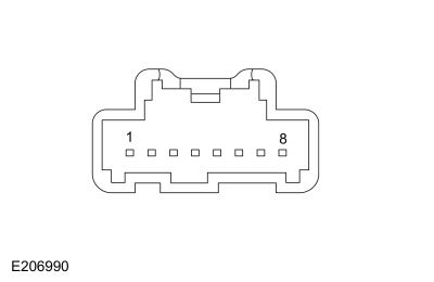 C552, pin 5, Component Side
|
|
C552, pin 6, Component Side
|
-
While pressing and releasing the indicated memory recall button 2, measure the component side resistance of the driver door lock control switch using the following table:
|
Positive Lead
|
Measurement / Action
|
Negative Lead
|
|
C552, pin 4, Component Side
|
|
C552, pin 6, Component Side
|
-
While pressing and releasing the indicated memory recall button 3, measure the component side resistance of the driver door lock control switch using the following table:
|
Positive Lead
|
Measurement / Action
|
Negative Lead
|
|
C552, pin 3, Component Side
|
|
C552, pin 6, Component Side
|
Are the resistances less than 20 ohms with the
switch buttons pressed and greater than 10,000 ohms with the switch
buttons released?
| No |
INSTALL a new door lock control switch.
REFER to: Front Door Lock Control Switch (501-14 Handles, Locks, Latches and Entry Systems, Removal and Installation).
|
|
| H5 CHECK THE MEMORY SET SWITCH GROUND CIRCUIT FOR AN OPEN |
-
Measure:
Click to display connectors
|
Positive Lead
|
Measurement / Action
|
Negative Lead
|
|
C552-6
|
|
Ground
|
Is the resistance less than 3 ohms?
|
| H6 CHECK THE MEMORY SET CIRCUITS FOR A SHORT TO VOLTAGE |
-
Measure:
Click to display connectors
|
Positive Lead
|
Measurement / Action
|
Negative Lead
|
|
C552-3
|
|
Ground
|
|
C552-4
|
|
Ground
|
|
C552-5
|
|
Ground
|
Is any voltage present?
| Yes |
REPAIR the affected circuit.
|
|
| H7 CHECK THE MEMORY SET SWITCH CIRCUITS FOR A SHORT TO GROUND |
-
Measure:
Click to display connectors
|
Positive Lead
|
Measurement / Action
|
Negative Lead
|
|
C552-3
|
|
Ground
|
|
C552-4
|
|
Ground
|
|
C552-5
|
|
Ground
|
Is the resistance greater than 10,000 ohms?
| No |
REPAIR the affected circuit.
|
|
| H8 CHECK THE MEMORY SET SWITCH CIRCUITS FOR AN OPEN |
-
Measure:
Click to display connectors
|
Positive Lead
|
Measurement / Action
|
Negative Lead
|
|
C552-3
|
|
C501B-2
|
|
C552-4
|
|
C501B-3
|
|
C552-5
|
|
C501B-1
|
Are the resistances less than 3 ohms?
| No |
REPAIR the affected circuit.
|
|
| H9 CHECK THE SEAT TRACK OPERATION USING DSM (DRIVER FRONT SEAT MODULE)
ACTIVE COMMANDS AND PARAMETER IDENTIFICATIONS (PIDS) |
-
Toggle the following DSM active commands ON and OFF using a diagnostic scan tool while monitoring the seat movement:
-
Front Motor Up (FRONT_UP)
-
Front Motor Down (FRONT_DWN)
-
Seat Height Motor Up (H_MOT_U)
-
Seat Height Motor Down (H_MOT_D)
-
Horizontal Motor Forward (HORZ_FWD)
-
Horizontal Motor Backward (HORZ_BWD)
-
Recline Motor Backward (RECL_BWD)
-
Recline Motor Forward (RECL_FWD)
Does the driver seat operate correctly?
| Yes |
The condition is intermittent. CHECK for causes of
an intermittent concern, particularly the pins and terminals of
electrical connectors that were disconnected. Do not install any new
components at this time. Components should only be installed when
directed to do so in the pinpoint test. REPAIR any intermittent wiring, terminal or connector concerns found.
|
| No |
DIAGNOSE the inoperative seat:
If equipped with a 10-way seat, GO to Pinpoint Test F
If equipped with a 16-way seat, GO to Pinpoint Test G
|
|
| H10 CHECK THE FRONT HEIGHT SENSOR CIRCUITS FOR A SHORT TO VOLTAGE |
-
REFER to: Supplemental Restraint System (SRS) Depowering (501-20B Supplemental Restraint System, General Procedures).
-
Disconnect: Driver Side Airbag In-line C3051.
-
Disconnect: DSM
C341A and C341F.
-
Disconnect: Driver Seat Front Height Motor C382.
-
Measure:
Click to display connectors
|
Positive Lead
|
Measurement / Action
|
Negative Lead
|
|
C382-2
|
|
Ground
|
|
C382-4
|
|
Ground
|
Is any voltage present?
| Yes |
REPAIR the affected circuit. GO to H32
|
|
| H11 CHECK THE FRONT HEIGHT SENSOR CIRCUITS FOR A SHORT TO GROUND |
-
Measure:
Click to display connectors
|
Positive Lead
|
Measurement / Action
|
Negative Lead
|
|
C382-2
|
|
Ground
|
|
C382-4
|
|
Ground
|
Are the resistances greater than 10,000 ohms?
| No |
REPAIR the affected circuit. GO to H32
|
|
| H12 CHECK THE FRONT HEIGHT SENSOR CIRCUITS FOR AN OPEN |
-
Measure:
Click to display connectors
|
Positive Lead
|
Measurement / Action
|
Negative Lead
|
|
C382-2
|
|
C341F-9
|
-
Measure:
Click to display connectors
|
Positive Lead
|
Measurement / Action
|
Negative Lead
|
|
C382-4
|
|
C341A-19
|
Are the resistances less than 3 ohms?
| Yes |
INSTALL a new driver seat track.
REFER to: Front Seat Track (501-10A Front Seats, Removal and Installation).
GO to H32
|
| No |
REPAIR the affected circuit. GO to H32
|
|
| H13 CHECK THE REAR HEIGHT SENSOR CIRCUITS FOR A SHORT TO VOLTAGE |
-
REFER to: Supplemental Restraint System (SRS) Depowering (501-20B Supplemental Restraint System, General Procedures).
-
Disconnect: Driver Side Airbag In-line C3051.
-
Disconnect: DSM
C341A and C341F.
-
Disconnect: Driver Seat Rear Height Motor C363.
-
Measure:
Click to display connectors
|
Positive Lead
|
Measurement / Action
|
Negative Lead
|
|
C363-2
|
|
Ground
|
|
C363-4
|
|
Ground
|
Is any voltage present on any circuits?
| Yes |
REPAIR the affected circuit. GO to H32
|
|
| H14 CHECK THE REAR HEIGHT SENSOR CIRCUITS FOR A SHORT TO GROUND |
-
Measure:
Click to display connectors
|
Positive Lead
|
Measurement / Action
|
Negative Lead
|
|
C363-2
|
|
Ground
|
|
C363-4
|
|
Ground
|
Are the resistances greater than 10,000 ohms?
| No |
REPAIR the affected circuit. GO to H32
|
|
| H15 CHECK THE REAR HEIGHT SENSOR CIRCUITS FOR AN OPEN |
-
Measure:
Click to display connectors
|
Positive Lead
|
Measurement / Action
|
Negative Lead
|
|
C363-2
|
|
C341A-18
|
-
Measure:
Click to display connectors
|
Positive Lead
|
Measurement / Action
|
Negative Lead
|
|
C363-4
|
|
C341F-9
|
Are the resistances less than 3 ohms?
| Yes |
INSTALL a new driver seat track.
REFER to: Front Seat Track (501-10A Front Seats, Removal and Installation).
GO to H32
|
| No |
REPAIR the affected circuit. GO to H32
|
|
| H16 CHECK THE HORIZONTAL SENSOR CIRCUITS FOR A SHORT TO VOLTAGE |
-
REFER to: Supplemental Restraint System (SRS) Depowering (501-20B Supplemental Restraint System, General Procedures).
-
Disconnect: Driver Side Airbag In-line C3051.
-
Disconnect: DSM
C341A and C341F.
-
Disconnect: Driver Seat Horizontal Motor C362.
-
Measure:
Click to display connectors
|
Positive Lead
|
Measurement / Action
|
Negative Lead
|
|
C362-2
|
|
Ground
|
|
C362-4
|
|
Ground
|
Is any voltage present on any circuits?
| Yes |
REPAIR the affected circuit. GO to H32
|
|
| H17 CHECK THE HORIZONTAL SENSOR CIRCUITS FOR A SHORT TO GROUND |
-
Measure:
Click to display connectors
|
Positive Lead
|
Measurement / Action
|
Negative Lead
|
|
C362-2
|
|
Ground
|
|
C362-4
|
|
Ground
|
Are the resistances greater than 10,000 ohms?
| No |
REPAIR the affected circuit. GO to H32
|
|
| H18 CHECK THE HORIZONTAL SENSOR CIRCUITS FOR AN OPEN |
-
Measure:
Click to display connectors
|
Positive Lead
|
Measurement / Action
|
Negative Lead
|
|
C362-2
|
|
C341F-9
|
-
Measure:
Click to display connectors
|
Positive Lead
|
Measurement / Action
|
Negative Lead
|
|
C362-4
|
|
C341A-20
|
Are the resistances less than 3 ohms?
| Yes |
INSTALL a new horizontal motor.
REFER to: Front Seat Track Motor (501-10A Front Seats, Removal and Installation).
GO to H32
|
| No |
REPAIR the affected circuit. GO to H32
|
|
| H19 CHECK THE RECLINER SENSOR CIRCUITS FOR A SHORT TO VOLTAGE |
-
REFER to: Supplemental Restraint System (SRS) Depowering (501-20B Supplemental Restraint System, General Procedures).
-
Disconnect: Driver Side Airbag In-line C3051.
-
Disconnect: DSM
C341A and C341F.
-
Disconnect: Driver Seat Recliner Motor C3187.
-
Measure:
Click to display connectors
|
Positive Lead
|
Measurement / Action
|
Negative Lead
|
|
C3187-2
|
|
Ground
|
|
C3187-4
|
|
Ground
|
Is any voltage present?
| Yes |
REPAIR the affected circuit. GO to H32
|
|
| H20 CHECK THE RECLINER SENSOR CIRCUITS FOR A SHORT TO GROUND |
-
Measure:
Click to display connectors
|
Positive Lead
|
Measurement / Action
|
Negative Lead
|
|
C3187-2
|
|
Ground
|
|
C3187-4
|
|
Ground
|
Are the resistances greater than 10,000 ohms?
| No |
REPAIR the affected circuit. GO to H32
|
|
| H21 CHECK THE RECLINER SENSOR CIRCUITS FOR AN OPEN |
-
Measure:
Click to display connectors
|
Positive Lead
|
Measurement / Action
|
Negative Lead
|
|
C3187-2
|
|
C341A-17
|
-
Measure:
Click to display connectors
|
Positive Lead
|
Measurement / Action
|
Negative Lead
|
|
C3187-4
|
|
C341F-9
|
Are the resistances less than 3 ohms?
| Yes |
INSTALL a new driver seat backrest frame. GO to H32
|
| No |
REPAIR the affected circuit. GO to H32
|
|
| H22 CHECK THE CUSHION EXTENSION MOTOR SENSOR CIRCUITS FOR A SHORT TO VOLTAGE |
-
REFER to: Supplemental Restraint System (SRS) Depowering (501-20B Supplemental Restraint System, General Procedures).
-
Disconnect: Driver Side Airbag In-line C3051.
-
Disconnect: DSM
C341A and C341F.
-
Disconnect: Driver Seat Cushion Extension Motor C3694.
-
Measure:
Click to display connectors
|
Positive Lead
|
Measurement / Action
|
Negative Lead
|
|
C3694-2
|
|
Ground
|
|
C3694-4
|
|
Ground
|
Is any voltage present?
| Yes |
REPAIR the affected circuit. GO to H32
|
|
| H23 CHECK THE CUSHION EXTENSION MOTOR SENSOR CIRCUITS FOR A SHORT TO GROUND |
-
Measure:
Click to display connectors
|
Positive Lead
|
Measurement / Action
|
Negative Lead
|
|
C3694-2
|
|
Ground
|
|
C3694-4
|
|
Ground
|
Are the resistances greater than 10,000 ohms?
| No |
REPAIR the affected circuit. GO to H32
|
|
| H24 CHECK THE CUSHION EXTENSION MOTOR SENSOR CIRCUITS FOR AN OPEN |
-
Measure:
Click to display connectors
|
Positive Lead
|
Measurement / Action
|
Negative Lead
|
|
C3694-2
|
|
C341F-9
|
-
Measure:
Click to display connectors
|
Positive Lead
|
Measurement / Action
|
Negative Lead
|
|
C3694-4
|
|
C341A-16
|
Are the resistances less than 3 ohms?
| Yes |
INSTALL a new driver seat track.
REFER to: Front Seat Track (501-10A Front Seats, Removal and Installation).
GO to H32
|
| No |
REPAIR the affected circuit. GO to H32
|
|
| H25 CHECK THE SEAT HEADREST MOTOR SENSOR CIRCUITS FOR A SHORT TO VOLTAGE |
-
REFER to: Supplemental Restraint System (SRS) Depowering (501-20B Supplemental Restraint System, General Procedures).
-
Disconnect: Driver Side Airbag In-line C3051.
-
Disconnect: DSM
C341A and C341F.
-
Disconnect: Driver Seat Headrest Up/Down Motor C3692.
-
Measure:
Click to display connectors
|
Positive Lead
|
Measurement / Action
|
Negative Lead
|
|
C3692-2
|
|
Ground
|
|
C3692-3
|
|
Ground
|
Is any voltage present?
| Yes |
REPAIR the affected circuit. GO to H32
|
|
| H26 CHECK THE SEAT HEADREST MOTOR SENSOR CIRCUITS FOR A SHORT TO GROUND |
-
Measure:
Click to display connectors
|
Positive Lead
|
Measurement / Action
|
Negative Lead
|
|
C3692-2
|
|
Ground
|
|
C3692-3
|
|
Ground
|
Are the resistances greater than 10,000 ohms?
| No |
REPAIR the affected circuit. GO to H32
|
|
| H27 CHECK THE SEAT HEADREST MOTOR SENSOR CIRCUITS FOR AN OPEN |
-
Measure:
Click to display connectors
|
Positive Lead
|
Measurement / Action
|
Negative Lead
|
|
C3692-3
|
|
C341F-9
|
-
Measure:
Click to display connectors
|
Positive Lead
|
Measurement / Action
|
Negative Lead
|
|
C3692-2
|
|
C341A-15
|
Are the resistances less than 3 ohms?
| Yes |
INSTALL a new driver seat head restraint assembly.
REFER to: Front Seat Head Restraint Motor - Vehicles With: Multi-Contour Seats (501-10A Front Seats, Removal and Installation).
GO to H32
|
| No |
REPAIR the affected circuit. GO to H32
|
|
| H28 CHECK THE SEAT HEAD RESTRAINT FORWARD/REARWARD MOTOR SENSOR CIRCUITS FOR A SHORT TO VOLTAGE |
-
REFER to: Supplemental Restraint System (SRS) Depowering (501-20B Supplemental Restraint System, General Procedures).
-
Disconnect: Driver Side Airbag In-line C3051.
-
Disconnect: DSM
C341A and C341F.
-
Disconnect: Driver Seat Head Restraint Forward/Rearward Motor C3701.
-
Measure:
Click to display connectors
|
Positive Lead
|
Measurement / Action
|
Negative Lead
|
|
C3701-2
|
|
Ground
|
|
C3701-3
|
|
Ground
|
Is any voltage present?
| Yes |
REPAIR the affected circuit. GO to H32
|
|
| H29 CHECK THE SEAT HEAD RESTRAINT FORWARD/REARWARD MOTOR SENSOR CIRCUITS FOR A SHORT TO GROUND |
-
Measure:
Click to display connectors
|
Positive Lead
|
Measurement / Action
|
Negative Lead
|
|
C3701-2
|
|
Ground
|
|
C3701-3
|
|
Ground
|
Are the resistances greater than 10,000 ohms?
| No |
REPAIR the affected circuit. GO to H32
|
|
| H30 CHECK THE SEAT HEAD RESTRAINT FORWARD/REARWARD MOTOR SENSOR CIRCUITS FOR AN OPEN |
-
Measure:
Click to display connectors
|
Positive Lead
|
Measurement / Action
|
Negative Lead
|
|
C3701-3
|
|
C341F-9
|
-
Measure:
Click to display connectors
|
Positive Lead
|
Measurement / Action
|
Negative Lead
|
|
C3701-2
|
|
C341A-14
|
Are the resistances less than 3 ohms?
| Yes |
INSTALL a new driver seat head restraint assembly.
REFER to: Front Seat Head Restraint Motor - Vehicles With: Multi-Contour Seats (501-10A Front Seats, Removal and Installation).
GO to H32
|
| No |
REPAIR the affected circuit. GO to H32
|
|
| H31 CHECK THE DDM (DRIVER DOOR MODULE)
OPERATION |
-
Disconnect and inspect all of the DDM connectors.
-
Repair:
-
corrosion (install new connector or terminals - clean module pins)
-
damaged or bent pins - install new terminals/pins as necessary
-
pushed-out pins - install new pins as necessary
-
Reconnect the DDM connectors. Make sure they seat and latch correctly.
-
Operate the system and determine if the concern is still present.
Is the concern still present?
| Yes |
CHECK OASIS for any applicable service articles: TSB , GSB , SSM or FSA
. If a service article exists for this concern, DISCONTINUE this test
and FOLLOW the service article instructions. If no service articles
address this concern, INSTALL a new DDM .
REFER to: Driver Door Module (DDM) (419-10 Multifunction Electronic Modules, Removal and Installation).
|
| No |
The system is operating correctly at this time. The
concern may have been caused by module connections. ADDRESS the root
cause of any connector or pin issues.
|
|
| H32 VERIFY THE SRS (SUPPLEMENTAL RESTRAINT SYSTEM)
PROVES OUT SUCCESSFULLY |
-
REFER to: Supplemental Restraint System (SRS) Depowering (501-20B Supplemental Restraint System, General Procedures).
-
Connect: Passenger Side Airbag In-line C339.
-
Connect all previously disconnected connectors.
-
REFER to: Supplemental Restraint System (SRS) Repowering (501-20B Supplemental Restraint System, General Procedures).
Did the SRS prove out successfully?
| Yes |
Repair is complete. RETURN the vehicle to the customer.
|
| No |
REFER to: Airbag Supplemental Restraint System (SRS) (501-20B Supplemental Restraint System, Diagnosis and Testing).
|
|
Easy Entry/Easy Exit is Inoperative/Does Not Operate Correctly
Normal Operation and Fault Conditions
REFER to: Front Seats - System Operation and Component Description (501-10A Front Seats, Description and Operation).
Possible Causes
-
Easy entry/exit feature is not enabled
-
Missing ignition status information
-
DSM
Visual Inspection and Diagnostic Pre-checks
-
Verify the easy entry/exit feature is enabled in the
message center. REFER to the Owner's Literature for information on
programming vehicle settings in the message center.
PINPOINT TEST I: EASY ENTRY/EASY EXIT IS INOPERATIVE/DOES NOT OPERATE CORRECTLY
| I1 CHECK THE DRIVER POWER SEAT OPERATION |
-
Check the message center to verify the easy entry/exit feature is turned on.
-
Using the seat control switch, verify the driver power seat operates fully forward and backward.
-
Using a diagnostic scan tool, perform the DSM self-test.
Are any Diagnostic Trouble Codes (DTCs) received?
| Yes |
REFER to the DSM
DTC Chart.
|
| No |
If disabled, ENABLE the easy entry/exit feature
through the message center. REFER to the Owner's Literature. TEST the
system for normal operation. If OK, INSTRUCT the customer on correct
system operation. GO to I2
|
|
| I2 CHECK THE DSM (DRIVER FRONT SEAT MODULE)
IGNITION POSITION FINAL STATUS PID (PARAMETER IDENTIFICATION)
STATES |
-
Using a diagnostic scan tool, monitor the DSM IGN_FINAL PID while cycling the ignition from ON to OFF and back to ON.
Does the PID states match with ignition mode?
| Yes |
INSTALL a new DSM .
REFER to: Driver Front Seat Module (DSM) (501-10A Front Seats, Removal and Installation).
|
| No |
DIAGNOSE the ignition status concern.
REFER to: Steering Wheel and
Column Electrical Components (211-05 Steering Wheel and Column
Electrical Components, Diagnosis and Testing).
|
|
Both Heated Seats Are Inoperative — Without Heated/Ventilated Seats
Refer to Wiring Diagrams Cell 119 for schematic and connector information.
Normal Operation and Fault Conditions
REFER to: Front Seats - System Operation and Component Description (501-10A Front Seats, Description and Operation).
Possible Causes
-
Fuse
-
Wiring, terminals or connectors
-
HVAC module
Visual Inspection and Diagnostic Pre-checks
-
Verify the BJB fuse 65 (20A) is OK.
PINPOINT TEST J: BOTH HEATED SEATS ARE INOPERATIVE — WITHOUT HEATED/VENTILATED SEATS
| J1 CHECK FOR HVAC (HEATING, VENTILATION AND AIR CONDITIONING)
MODULE DIAGNOSTIC TROUBLE CODES (DTCS) |
-
Using a diagnostic scan tool, perform HVAC module self-test.
Are any HVAC module Diagnostic Trouble Codes (DTCs) present?
| Yes |
REFER to the HVAC Module DTC Chart.
|
|
| J2 CHECK THE HEATED SEAT VOLTAGE SUPPLY CIRCUIT FOR AN OPEN |
-
Disconnect: HVAC module C228B.
-
Measure:
Click to display connectors
|
Positive Lead
|
Measurement / Action
|
Negative Lead
|
|
C228B-1
|
|
Ground
|
Is the voltage greater than 11 volts?
| No |
VERIFY BJB
fuse 65 (20A) is OK. If OK, REPAIR the circuit. If not OK, REFER to
the Wiring Diagrams manual to identify the possible causes of the
circuit short.
|
|
| J3 CHECK THE HVAC (HEATING, VENTILATION AND AIR CONDITIONING)
MODULE OPERATION |
-
Disconnect and inspect all of the HVAC module connectors.
-
Repair:
-
corrosion (install new connector or terminals - clean module pins)
-
damaged or bent pins - install new terminals/pins as necessary
-
pushed-out pins - install new pins as necessary
-
Reconnect the HVAC module connectors. Make sure they seat and latch correctly.
-
Reconnect all previously disconnected connectors.
-
Operate the system and determine if the concern is still present.
Is the concern still present?
| Yes |
CHECK OASIS for any applicable service articles: TSB , GSB , SSM or FSA
. If a service article exists for this concern, DISCONTINUE this test
and FOLLOW the service article instructions. If no service articles
address this concern, INSTALL a new HVAC module.
REFER to: Heating,
Ventilation and Air Conditioning (HVAC) Control Module (412-00 Climate
Control System - General Information, Removal and Installation).
|
| No |
The system is operating correctly at this time. The
concern may have been caused by module connections. ADDRESS the root
cause of any connector or pin issues.
|
|
The Driver Heated Seat Is Inoperative/Does Not Operate Correctly — Without Heated/Ventilated Seats
Refer to Wiring Diagrams Cell 119 for schematic and connector information.
Normal Operation and Fault Conditions
REFER to: Front Seats - System Operation and Component Description (501-10A Front Seats, Description and Operation).
DTC Fault Trigger Conditions
|
DTC
|
Description
|
Fault Trigger Conditions
|
|
B1034:11
|
Left Front Seat Heater Element: Circuit Short To Ground
|
Sets when the HVAC module senses the left front heater element current
draw has exceeded a specified threshold. When this DTC sets, the HVAC
module disables the circuit until the ignition is cycled.
|
|
B1034:15
|
Left Front Seat Heater Element: Circuit Short To Battery or Open
|
Sets when the HVAC module senses the left front heater circuit voltage
is above a specified threshold when the driver is active. When this DTC
sets, the HVAC module disables the circuit until the ignition is cycled.
|
|
B1038:11
|
Left Front Seat Heater Sensor: Circuit Short To Ground
|
Sets when the HVAC module senses the left front heater sensor voltage
is out-of-range low. When this DTC sets, the HVAC module disables the
circuit until the ignition is cycled.
|
|
B1038:15
|
Left Front Seat Heater Sensor: Circuit Short To Battery or Open
|
Sets when the HVAC module senses the left front heater sensor voltage
is out-of-range high. When this DTC sets, the HVAC module disables the
circuit until the ignition is cycled.
|
Possible Causes
-
Wiring, terminals or connectors
-
Heater mat
-
Touchscreen
-
HVAC module
PINPOINT TEST K: THE DRIVER HEATED SEAT IS INOPERATIVE/DOES NOT OPERATE CORRECTLY — WITHOUT HEATED/VENTILATED SEATS
|
WARNING:
Incorrect repair techniques or actions can cause an
accidental Supplemental Restraint System (SRS) deployment. Never
compromise or depart from these instructions. Failure to precisely
follow all instructions could result in serious personal injury from an
accidental deployment.
|
| K1 CHECK FOR HVAC (HEATING, VENTILATION AND AIR CONDITIONING)
MODULE DIAGNOSTIC TROUBLE CODES (DTCS) |
-
Using a diagnostic scan tool, perform HVAC module self-test.
Are any HVAC module Diagnostic Trouble Codes (DTCs) present?
| Yes |
For DTC B1034:11 or B1034:15, GO to K4
For DTC B1038:11 or B1038:15, GO to K6
For all other Diagnostic Trouble Codes (DTCs), REFER to the HVAC Module DTC Chart.
|
|
| K2 CHECK THE HVAC (HEATING, VENTILATION AND AIR CONDITIONING)
MODULE DRIVER HEATED SEAT CONTROL SWITCH (CC_SW_D_HSEATS) PID (PARAMETER IDENTIFICATION)
|
-
Using a diagnostic scan tool, monitor the HVAC module CC_SW_D_HSEATS PID while operating the driver heated seat switch.
Does the PID state change when the driver heated seat switch is pressed and released?
| No |
If any other climate control system features are
also inoperative from the touchscreen, DIAGNOSE the inoperative climate
control system.
REFER to: Climate Control System (412-00 Climate Control System - General Information, Diagnosis and Testing).
Otherwise, GO to K14
|
|
| K3 CHECK THE HEATED SEAT VOLTAGE SUPPLY CIRCUIT FOR AN OPEN |
-
Disconnect: HVAC Module C228B.
-
Measure:
Click to display connectors
|
Positive Lead
|
Measurement / Action
|
Negative Lead
|
|
C228B-1
|
|
Ground
|
Is the voltage greater than 11 volts?
|
| K4 CHECK THE HEATER ELEMENT POWER CIRCUIT FOR A SHORT TO VOLTAGE |
-
REFER to: Supplemental Restraint System (SRS) Depowering (501-20B Supplemental Restraint System, General Procedures).
-
Disconnect: Driver Side Airbag In-line C3051.
-
Disconnect: HVAC Module C228B (if not previously disconnected).
-
Disconnect: Left Front Seat Cushion Heater C364.
-
Measure:
Click to display connectors
|
Positive Lead
|
Measurement / Action
|
Negative Lead
|
|
C364-1
|
|
Ground
|
Is any voltage present?
| Yes |
REPAIR the circuit. GO to K15
|
|
| K5 CHECK THE HEATER ELEMENT POWER CIRCUIT FOR AN OPEN OR SHORT TO GROUND |
-
Measure:
Click to display connectors
|
Positive Lead
|
Measurement / Action
|
Negative Lead
|
|
C364-1
|
|
Ground
|
-
Measure:
Click to display connectors
|
Positive Lead
|
Measurement / Action
|
Negative Lead
|
|
C364-1
|
|
C228B-16
|
Is the resistance greater than 10,000 ohms between
the driver seat cushion heater mat and ground; and less than 3 ohms
between the driver seat cushion heater mat and the HVAC module?
| No |
REPAIR the circuit. GO to K15
|
|
| K6 CHECK THE HEATED SEAT TEMPERATURE SENSOR CIRCUIT FOR AN OPEN OR SHORT TO GROUND |
-
REFER to: Supplemental Restraint System (SRS) Depowering (501-20B Supplemental Restraint System, General Procedures).
-
Disconnect: Driver Side Airbag In-line C3051.
-
Disconnect: HVAC Module C228B.
-
Disconnect: Left Front Seat Cushion Heater C364.
-
Measure:
Click to display connectors
|
Positive Lead
|
Measurement / Action
|
Negative Lead
|
|
C364-2
|
|
Ground
|
-
Measure:
Click to display connectors
|
Positive Lead
|
Measurement / Action
|
Negative Lead
|
|
C364-2
|
|
C228B-30
|
Is the resistance greater than 10,000 ohms between
the driver seat cushion heater mat and ground; and less than 3 ohms
between the driver seat cushion heater mat and the HVAC module?
| No |
REPAIR the circuit. GO to K15
|
|
| K7 CHECK THE HEATED SEAT TEMPERATURE SENSOR RETURN CIRCUIT FOR AN OPEN OR SHORT TO GROUND |
-
Disconnect: HVAC Module C228A.
-
Measure:
Click to display connectors
|
Positive Lead
|
Measurement / Action
|
Negative Lead
|
|
C364-3
|
|
Ground
|
-
Measure:
Click to display connectors
|
Positive Lead
|
Measurement / Action
|
Negative Lead
|
|
C364-3
|
|
C228A-2
|
Is the resistance greater than 10,000 ohms between
the driver seat cushion heater mat and ground; and less than 3 ohms
between the driver seat cushion heater mat and the HVAC module?
| No |
REPAIR the open circuit or REFER to the Wiring
Diagrams manual to identify the possible causes of the circuit short. GO
to K15
|
|
| K8 CHECK THE HEATED SEAT TEMPERATURE SENSOR CIRCUIT FOR A SHORT TO VOLTAGE |
-
Measure:
Click to display connectors
|
Positive Lead
|
Measurement / Action
|
Negative Lead
|
|
C364-2
|
|
Ground
|
Is any voltage present?
| Yes |
REPAIR the circuit. GO to K15
|
|
| K9 CHECK THE HEATER ELEMENT GROUND CIRCUIT FOR AN OPEN |
-
Disconnect: Left Front Seat Backrest Heater C365.
-
Measure:
Click to display connectors
|
Positive Lead
|
Measurement / Action
|
Negative Lead
|
|
C365-2
|
|
Ground
|
Is the resistance less than 0.5 ohm?
| No |
REPAIR the circuit. GO to K15
|
|
| K10 CHECK THE CUSHION HEATED SEAT MAT FOR AN OPEN OR SHORT TO GROUND |
-
Measure the component side resistance between:
|
Positive Lead
|
Measurement / Action
|
Negative Lead
|
.jpg) C364-1, Component Side
C364-1, Component Side
|
|
C364-4, Component Side
|
|
C364-1, Component Side
|
|
Ground
|
Is the resistance between 0.6 and 2 ohms between
pins 1 and 4; and greater than 10,000 ohms between pin 1 and ground?
| No |
INSTALL a new driver seat cushion heater mat.
REFER to: Seat Heater Mat Removal (501-10A Front Seats, General Procedures).
GO to K15
|
|
| K11 CHECK THE BACKREST HEATED SEAT MAT FOR AN OPEN OR SHORT TO GROUND |
-
Measure the component side resistance between:
|
Positive Lead
|
Measurement / Action
|
Negative Lead
|
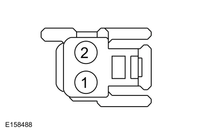 C365-1, Component Side
|
|
C365-2, Component Side
|
|
C365-2, Component Side
|
|
Ground
|
Is the resistance between 0.6 and 2 ohms between
pins 1 and 2; and greater than 10,000 ohms between pin 2 and ground?
| No |
INSTALL a new driver seat backrest heater mat.
REFER to: Seat Heater Mat Removal (501-10A Front Seats, General Procedures).
GO to K15
|
|
| K12 CHECK THE CIRCUIT BETWEEN THE CUSHION HEATER MAT AND BACKREST HEATER MAT FOR AN OPEN AND SHORT TO GROUND |
-
Measure:
Click to display connectors
|
Positive Lead
|
Measurement / Action
|
Negative Lead
|
|
C364-4
|
|
Ground
|
-
Measure:
Click to display connectors
|
Positive Lead
|
Measurement / Action
|
Negative Lead
|
|
C364-4
|
|
C365-1
|
Is the resistance greater than 10,000 ohms between
the driver seat cushion heater mat and ground; and less than 3 ohms
between the driver seat cushion heater mat and the backrest heater mat?
| No |
REPAIR the circuit. GO to K15
|
|
| K13 CHECK THE HEATED SEAT TEMPERATURE SENSOR FOR AN OPEN OR SHORT TO GROUND |
-
Measure the component side resistance between:
|
Positive Lead
|
Measurement / Action
|
Negative Lead
|
|
C364-2, Component Side
|
|
C364-3, Component Side
|
|
C364-2, Component Side
|
|
Ground
|
Is the resistance between 300 and 300,000 ohms
between pins 2 and 3; and greater than 10,000 ohms between pin 2 and
ground?
| No |
INSTALL a new driver seat cushion heater mat.
REFER to: Seat Heater Mat Removal (501-10A Front Seats, General Procedures).
GO to K15
|
|
| K14 CHECK THE HVAC (HEATING, VENTILATION AND AIR CONDITIONING)
MODULE OPERATION |
-
Disconnect and inspect all of the HVAC module connectors.
-
Repair:
-
corrosion (install new connector or terminals - clean module pins)
-
damaged or bent pins - install new terminals/pins as necessary
-
pushed-out pins - install new pins as necessary
-
Reconnect the HVAC module connectors. Make sure they seat and latch correctly.
-
NOTE:
Do not reconnect Driver Side Airbag In-line C3051 at this time.
Reconnect all previously disconnected connectors.
-
Operate the system and determine if the concern is still present.
Is the concern still present?
| Yes |
CHECK OASIS for any applicable service articles: TSB , GSB , SSM or FSA
. If a service article exists for this concern, DISCONTINUE this test
and FOLLOW the service article instructions. If no service articles
address this concern, INSTALL a new HVAC module.
REFER to: Heating,
Ventilation and Air Conditioning (HVAC) Control Module (412-00 Climate
Control System - General Information, Removal and Installation).
GO to K15
|
| No |
The system is operating correctly at this time. The
concern may have been caused by module connections. ADDRESS the root
cause of any connector or pin issues. GO to K15
|
|
| K15 VERIFY THE SRS (SUPPLEMENTAL RESTRAINT SYSTEM)
PROVES OUT SUCCESSFULLY |
-
REFER to: Supplemental Restraint System (SRS) Depowering (501-20B Supplemental Restraint System, General Procedures).
-
Connect: Driver Side Airbag In-line C3051.
-
Connect all previously disconnected connectors.
-
REFER to: Supplemental Restraint System (SRS) Repowering (501-20B Supplemental Restraint System, General Procedures).
Did the SRS prove out successfully?
| Yes |
Repair is complete. RETURN the vehicle to the customer.
|
| No |
REFER to: Airbag Supplemental Restraint System (SRS) (501-20B Supplemental Restraint System, Diagnosis and Testing).
|
|
The Passenger Heated Seat Is Inoperative/Does Not Operate Correctly — Without Heated/Ventilated Seats
Refer to Wiring Diagrams Cell 119 for schematic and connector information.
Normal Operation and Fault Conditions
REFER to: Front Seats - System Operation and Component Description (501-10A Front Seats, Description and Operation).
DTC Fault Trigger Conditions
|
DTC
|
Description
|
Fault Trigger Conditions
|
|
B1036:11
|
Right Front Seat Heater Element: Circuit Short To Ground
|
Sets when the HVAC module senses the right front heater element current
draw has exceeded a specified threshold. When this DTC sets, the HVAC
module disables the circuit until the ignition is cycled.
|
|
B1036:15
|
Right Front Seat Heater Element: Circuit Short To Battery or Open
|
Sets when the HVAC module senses the right front heater circuit voltage
is above a specified threshold when the driver is active. When this DTC
sets, the HVAC module disables the circuit until the ignition is
cycled.
|
|
B103A:11
|
Right Front Seat Heater Sensor: Circuit Short To Ground
|
Sets when the HVAC module senses the right front heater sensor voltage
is out-of-range low. When this DTC sets, the HVAC module disables the
circuit until the ignition is cycled.
|
|
B103A:15
|
Right Front Seat Heater Sensor: Circuit Short To Battery or Open
|
Sets when the HVAC module senses the right front heater sensor voltage
is out-of-range high. When this DTC sets, the HVAC module disables the
circuit until the ignition is cycled.
|
Possible Causes
-
Wiring, terminals or connectors
-
Heater mat
-
Touchscreen
-
HVAC module
PINPOINT TEST L: THE PASSENGER HEATED SEAT IS INOPERATIVE/DOES NOT OPERATE CORRECTLY — WITHOUT HEATED/VENTILATED SEATS
|
WARNING:
Incorrect repair techniques or actions can cause an
accidental Supplemental Restraint System (SRS) deployment. Never
compromise or depart from these instructions. Failure to precisely
follow all instructions could result in serious personal injury from an
accidental deployment.
|
| L1 CHECK FOR HVAC (HEATING, VENTILATION AND AIR CONDITIONING)
MODULE DIAGNOSTIC TROUBLE CODES (DTCS) |
-
Using a diagnostic scan tool, perform HVAC module self-test.
Are any HVAC module Diagnostic Trouble Codes (DTCs) present?
| Yes |
For DTC B1036:11 or B1036:15, GO to L4
For DTC B103A:11 or B103A:15, GO to L6
For all other Diagnostic Trouble Codes (DTCs), REFER to the HVAC Module DTC Chart.
|
|
| L2 CHECK THE HVAC (HEATING, VENTILATION AND AIR CONDITIONING)
MODULE PASSENGER HEATED SEAT CONTROL SWITCH (CC_SW_P_HSEATS) PID (PARAMETER IDENTIFICATION)
|
-
Using a diagnostic scan tool, monitor the HVAC module CC_SW_P_HSEATS PID while operating the passenger heated seat switch.
Does the PID state change when the passenger heated seat switch is pressed and released?
| No |
If any other climate control system features are
also inoperative from the touchscreen, DIAGNOSE the inoperative climate
control system.
REFER to: Climate Control System (412-00 Climate Control System - General Information, Diagnosis and Testing).
Otherwise, GO to L14
|
|
| L3 CHECK THE HEATED SEAT VOLTAGE SUPPLY CIRCUIT FOR AN OPEN |
-
Disconnect: HVAC Module C228B.
-
Measure:
Click to display connectors
|
Positive Lead
|
Measurement / Action
|
Negative Lead
|
|
C228B-2
|
|
Ground
|
Is the voltage greater than 11 volts?
|
| L4 CHECK THE HEATER ELEMENT POWER CIRCUIT FOR A SHORT TO VOLTAGE |
-
REFER to: Supplemental Restraint System (SRS) Depowering (501-20B Supplemental Restraint System, General Procedures).
-
Disconnect: Passenger Side Airbag In-line C339.
-
Disconnect: HVAC Module C228B (if not previously disconnected).
-
Disconnect: Right Front Seat Cushion Heater C334.
-
Measure:
Click to display connectors
|
Positive Lead
|
Measurement / Action
|
Negative Lead
|
|
C334-1
|
|
Ground
|
Is any voltage present?
| Yes |
REPAIR the circuit. GO to L15
|
|
| L5 CHECK THE HEATER ELEMENT POWER CIRCUIT FOR AN OPEN OR SHORT TO GROUND |
-
Measure:
Click to display connectors
|
Positive Lead
|
Measurement / Action
|
Negative Lead
|
|
C334-1
|
|
Ground
|
-
Measure:
Click to display connectors
|
Positive Lead
|
Measurement / Action
|
Negative Lead
|
|
C334-1
|
|
C228B-17
|
Is the resistance greater than 10,000 ohms between
the passenger seat cushion heater mat and ground; and less than 3 ohms
between the passenger seat cushion heater mat and the HVAC module?
| No |
REPAIR the circuit. GO to L15
|
|
| L6 CHECK THE HEATED SEAT TEMPERATURE SENSOR CIRCUIT FOR AN OPEN OR SHORT TO GROUND |
-
REFER to: Supplemental Restraint System (SRS) Depowering (501-20B Supplemental Restraint System, General Procedures).
-
Disconnect: Passenger Side Airbag In-line C339.
-
Disconnect: HVAC Module C228B.
-
Disconnect: Right Front Seat Cushion Heater C334.
-
Measure:
Click to display connectors
|
Positive Lead
|
Measurement / Action
|
Negative Lead
|
|
C334-2
|
|
Ground
|
-
Measure:
Click to display connectors
|
Positive Lead
|
Measurement / Action
|
Negative Lead
|
|
C334-2
|
|
C228B-15
|
Is the resistance greater than 10,000 ohms between
the passenger seat cushion heater mat and ground; and less than 3 ohms
between the passenger seat cushion heater mat and the HVAC module?
| No |
REPAIR the circuit. GO to L15
|
|
| L7 CHECK THE HEATED SEAT TEMPERATURE SENSOR RETURN CIRCUIT FOR AN OPEN OR SHORT TO GROUND |
-
Disconnect: HVAC Module C228A.
-
Measure:
Click to display connectors
|
Positive Lead
|
Measurement / Action
|
Negative Lead
|
|
C334-3
|
|
Ground
|
-
Measure:
Click to display connectors
|
Positive Lead
|
Measurement / Action
|
Negative Lead
|
|
C334-3
|
|
C228A-2
|
Is the resistance greater than 10,000 ohms between
the passenger seat cushion heater mat and ground; and less than 3 ohms
between the passenger seat cushion heater mat and the HVAC module?
| No |
REPAIR the open circuit or REFER to the Wiring
Diagrams manual to identify the possible causes of the circuit short. GO
to L15
|
|
| L8 CHECK THE HEATED SEAT TEMPERATURE SENSOR CIRCUIT FOR A SHORT TO VOLTAGE |
-
Measure:
Click to display connectors
|
Positive Lead
|
Measurement / Action
|
Negative Lead
|
|
C334-2
|
|
Ground
|
Is any voltage present?
| Yes |
REPAIR the circuit. GO to L15
|
|
| L9 CHECK THE HEATER ELEMENT GROUND CIRCUIT FOR AN OPEN |
-
Disconnect: Right Front Seat Backrest Heater C335.
-
Measure:
Click to display connectors
|
Positive Lead
|
Measurement / Action
|
Negative Lead
|
|
C335-2
|
|
Ground
|
Is the resistance less than 0.5 ohm?
| No |
REPAIR the circuit. GO to L15
|
|
| L10 CHECK CUSHION HEATED SEAT MAT FOR AN OPEN OR SHORT TO GROUND |
-
Measure the component side resistance between:
|
Positive Lead
|
Measurement / Action
|
Negative Lead
|
|
C334-1, Component Side
|
|
C334-4, Component Side
|
|
C334-1, Component Side
|
|
Ground
|
Is the resistance between 0.6 and 2 ohms between
pins 1 and 4; and greater than 10,000 ohms between pin 1 and ground?
| No |
INSTALL a new passenger seat cushion heater mat.
REFER to: Seat Heater Mat Removal (501-10A Front Seats, General Procedures).
GO to L15
|
|
| L11 CHECK THE BACKREST HEATED SEAT MAT FOR AN OPEN OR SHORT TO GROUND |
-
Measure the component side resistance between:
|
Positive Lead
|
Measurement / Action
|
Negative Lead
|
|
C335-1, Component Side
|
|
C335-2, Component Side
|
|
C335-2, Component Side
|
|
Ground
|
Is the resistance between 0.6 and 2 ohms between
pins 1 and 2; and greater than 10,000 ohms between pin 2 and ground?
| No |
INSTALL a new passenger seat backrest heater mat.
REFER to: Seat Heater Mat Removal (501-10A Front Seats, General Procedures).
GO to L15
|
|
| L12 CHECK THE CIRCUIT BETWEEN THE CUSHION HEATER MAT AND BACKREST HEATER MAT FOR AN OPEN AND SHORT TO GROUND |
-
Measure:
Click to display connectors
|
Positive Lead
|
Measurement / Action
|
Negative Lead
|
|
C334-4
|
|
Ground
|
-
Measure:
Click to display connectors
|
Positive Lead
|
Measurement / Action
|
Negative Lead
|
|
C334-4
|
|
C335-1
|
Is the resistance greater than 10,000 ohms between
the passenger seat cushion heater mat and ground; and less than 3 ohms
between the passenger seat cushion heater mat and the backrest heater
mat?
| No |
REPAIR the circuit. GO to L15
|
|
| L13 CHECK THE HEATED SEAT TEMPERATURE SENSOR FOR AN OPEN OR SHORT TO GROUND |
-
Measure the component side resistance between:
|
Positive Lead
|
Measurement / Action
|
Negative Lead
|
|
C334-2, Component Side
|
|
C334-3, Component Side
|
|
C334-2, Component Side
|
|
Ground
|
Is the resistance between 300 and 300,000 ohms
between pins 2 and 3; and greater than 10,000 ohms between pin 2 and
ground?
| No |
INSTALL a new driver seat cushion heater mat.
REFER to: Seat Heater Mat Removal (501-10A Front Seats, General Procedures).
GO to L15
|
|
| L14 CHECK THE HVAC (HEATING, VENTILATION AND AIR CONDITIONING)
MODULE OPERATION |
-
Disconnect and inspect all of the HVAC module connectors.
-
Repair:
-
corrosion (install new connector or terminals - clean module pins)
-
damaged or bent pins - install new terminals/pins as necessary
-
pushed-out pins - install new pins as necessary
-
Reconnect the HVAC module connectors. Make sure they seat and latch correctly.
-
NOTE:
Do not reconnect Passenger Side Airbag In-line C339 at this time.
Reconnect all previously disconnected connectors.
-
Operate the system and determine if the concern is still present.
Is the concern still present?
| Yes |
CHECK OASIS for any applicable service articles: TSB , GSB , SSM or FSA
. If a service article exists for this concern, DISCONTINUE this test
and FOLLOW the service article instructions. If no service articles
address this concern, INSTALL a new HVAC module.
REFER to: Heating,
Ventilation and Air Conditioning (HVAC) Control Module (412-00 Climate
Control System - General Information, Removal and Installation).
GO to L15
|
| No |
The system is operating correctly at this time. The
concern may have been caused by module connections. ADDRESS the root
cause of any connector or pin issues. GO to L15
|
|
| L15 VERIFY THE SRS (SUPPLEMENTAL RESTRAINT SYSTEM)
PROVES OUT SUCCESSFULLY |
-
REFER to: Supplemental Restraint System (SRS) Depowering (501-20B Supplemental Restraint System, General Procedures).
-
Connect: Passenger Side Airbag In-line C339.
-
Connect all previously disconnected connectors.
-
REFER to: Supplemental Restraint System (SRS) Repowering (501-20B Supplemental Restraint System, General Procedures).
Did the SRS prove out successfully?
| Yes |
Repair is complete. RETURN the vehicle to the customer.
|
| No |
REFER to: Airbag Supplemental Restraint System (SRS) (501-20B Supplemental Restraint System, Diagnosis and Testing).
|
|
Both Heated Seats are Inoperative — With Heated/Ventilated Seats
Refer to Wiring Diagrams Cell 119 for schematic and connector information.
Normal Operation and Fault Conditions
REFER to: Front Seats - System Operation and Component Description (501-10A Front Seats, Description and Operation).
Possible Causes
-
Fuse
-
Wiring, terminals or connectors
-
SCME
Visual Inspection and Diagnostic Pre-checks
-
Verify the BJB fuse 77 (30A) is OK.
PINPOINT TEST M: BOTH HEATED SEATS ARE INOPERATIVE — WITH HEATED/VENTILATED SEATS
| M1 CHECK FOR SCME (FRONT SEAT CLIMATE CONTROL MODULE)
DIAGNOSTIC TROUBLE CODES (DTCS) |
-
Using a diagnostic scan tool, perform SCME self-test.
Are any SCME Diagnostic Trouble Codes (DTCs) present?
| Yes |
REFER to the SCME
DTC Chart in this section.
|
|
| M2 CHECK THE HEATED SEAT VOLTAGE SUPPLY CIRCUITS FOR AN OPEN |
-
REFER to: Supplemental Restraint System (SRS) Depowering (501-20B Supplemental Restraint System, General Procedures).
-
Disconnect: Driver Side Airbag In-line C3051.
-
Disconnect: DSM Module C341B.
-
Measure:
Click to display connectors
|
Positive Lead
|
Measurement / Action
|
Negative Lead
|
|
C341B-8
|
|
Ground
|
|
C341B-9
|
|
Ground
|
Are the voltages greater than 11 volts?
| No |
VERIFY BJB
fuse 77 (30A) is OK. If OK, REPAIR the circuit in question. If not
OK, REFER to the Wiring Diagrams manual to identify the possible causes
of the circuit short. GO to M5
|
|
| M3 CHECK THE HEATED SEAT GROUND CIRCUITS FOR AN OPEN |
-
Disconnect: DSM Module C341C.
-
Measure:
Click to display connectors
|
Positive Lead
|
Measurement / Action
|
Negative Lead
|
|
C341C-7
|
|
Ground
|
|
C341C-8
|
|
Ground
|
Are the resistances less than 3 ohms?
| No |
REPAIR the circuit in question. GO to M5
|
|
| M4 CHECK THE SCME (FRONT SEAT CLIMATE CONTROL MODULE)
OPERATION |
-
Disconnect and inspect all of the SCME connectors.
-
Repair:
-
corrosion (install new connector or terminals - clean module pins)
-
damaged or bent pins - install new terminals/pins as necessary
-
pushed-out pins - install new pins as necessary
-
Reconnect the SCME connectors. Make sure they seat and latch correctly.
-
Reconnect all previously disconnected connectors.
-
Operate the system and determine if the concern is still present.
Is the concern still present?
| Yes |
CHECK OASIS for any applicable service articles: TSB , GSB , SSM or FSA
. If a service article exists for this concern, DISCONTINUE this test
and FOLLOW the service article instructions. If no service articles
address this concern, INSTALL a new SCME .
REFER to: Driver Front Seat Module (DSM) (501-10A Front Seats, Removal and Installation).
GO to M5
|
| No |
The system is operating correctly at this time. The
concern may have been caused by module connections. ADDRESS the root
cause of any connector or pin issues. GO to M5
|
|
| M5 VERIFY THE SRS (SUPPLEMENTAL RESTRAINT SYSTEM)
PROVES OUT SUCCESSFULLY |
-
REFER to: Supplemental Restraint System (SRS) Depowering (501-20B Supplemental Restraint System, General Procedures).
-
Connect: Driver Side Airbag In-line C3051.
-
Connect all previously disconnected connectors.
-
REFER to: Supplemental Restraint System (SRS) Repowering (501-20B Supplemental Restraint System, General Procedures).
Did the SRS prove out successfully?
| Yes |
Repair is complete. RETURN the vehicle to the customer.
|
| No |
REFER to: Airbag Supplemental Restraint System (SRS) (501-20B Supplemental Restraint System, Diagnosis and Testing).
|
|
The Left Heated Seat is Inoperative — With Heated/Ventilated Seats
Refer to Wiring Diagrams Cell 119 for schematic and connector information.
Normal Operation and Fault Conditions
REFER to: Front Seats - System Operation and Component Description (501-10A Front Seats, Description and Operation).
DTC Fault Trigger Conditions
|
DTC
|
Description
|
Fault Trigger Conditions
|
|
B1153:4B
|
Driver Seat Cushion: Over Temperature
|
Sets when the SCME senses the left front cushion temperature has
exceeded 110°C (230°F) for more than 4 seconds. When this DTC sets, the
SCME disables the circuit until the ignition is cycled.
|
|
B1156:01
|
Driver Seat: General Electrical Failure
|
Sets when the SCME senses the left front heater element current draw
has exceeded a specified threshold. When this DTC sets, the SCME
disables the circuit until the ignition is cycled.
|
|
B1156:11
|
Driver Seat: Circuit Short To Ground
|
Sets when the SCME senses the left front heater element current draw
has exceeded a specified threshold. When this DTC sets, the SCME
disables the circuit until the ignition is cycled.
|
|
B1156:12
|
Driver Seat: Circuit Short To Battery
|
Sets when the SCME senses the left front heater circuit voltage is
above a specified threshold when the driver is active. When this DTC
sets, the SCME disables the circuit until the ignition is cycled.
|
|
B1156:13
|
Driver Seat: Circuit Open
|
Sets when the SCME senses the left front heater element current draw is
less than a specified threshold. When this DTC sets, the SCME disables
the circuit until the ignition is cycled.
|
|
B1156:1A
|
Driver Seat: Circuit Resistance Below Threshold
|
Sets when the SCME senses the left front heater element current draw is
more than a specified threshold. When this DTC sets, the SCME disables
the circuit until the ignition is cycled.
|
|
B1208:01
|
Driver Seat Cushion Temperature Sensor: General Electrical Failure
|
Sets when the SCME senses the left front heater sensor voltage is
out-of-range low or high. When this DTC sets, the SCME disables the
circuit until the ignition is cycled.
|
|
B1208:11
|
Driver Seat Cushion Temperature Sensor: Circuit Short To Ground
|
Sets when the SCME senses the left front heater sensor voltage is
out-of-range low. When this DTC sets, the SCME disables the circuit
until the ignition is cycled.
|
|
B1208:15
|
Driver Seat Cushion Temperature Sensor: Circuit Short To Battery or Open
|
Sets when the SCME senses the left front heater sensor voltage is
out-of-range high. When this DTC sets, the SCME disables the circuit
until the ignition is cycled.
|
Possible Causes
-
Wiring, terminals or connectors
-
Heater mat
-
Touchscreen
-
SCME
PINPOINT TEST N: THE LEFT HEATED SEAT IS INOPERATIVE — WITH HEATED/VENTILATED SEATS
|
WARNING:
Incorrect repair techniques or actions can cause an
accidental Supplemental Restraint System (SRS) deployment. Never
compromise or depart from these instructions. Failure to precisely
follow all instructions could result in serious personal injury from an
accidental deployment.
|
| N1 CHECK FOR SCME (FRONT SEAT CLIMATE CONTROL MODULE)
DIAGNOSTIC TROUBLE CODES (DTCS) |
-
Using a diagnostic scan tool, perform SCME self-test.
Are any SCME Diagnostic Trouble Codes (DTCs) present?
| Yes |
For DTC B1156:01, B1156:11, B1156:12, B1156:13 or B1156:1A, GO to N5
For DTC B1153:4B, B1208:01, B1208:11 or B1208:15, GO to N7
For all other Diagnostic Trouble Codes (DTCs), REFER to the SCME
DTC Chart.
|
|
| N2 CHECK THE CLIMATE CONTROL OPERATION FROM THE TOUCHSCREEN |
-
Using the touchscreen, operate the climate control system and verify operation.
Does the climate control system function when controlled by the touchscreen?
| No |
DIAGNOSE the inoperative climate control system.
REFER to: Climate Control System (412-00 Climate Control System - General Information, Diagnosis and Testing).
|
|
| N3 CHECK THE HEATED SEAT VOLTAGE SUPPLY CIRCUITS FOR AN OPEN |
-
REFER to: Supplemental Restraint System (SRS) Depowering (501-20B Supplemental Restraint System, General Procedures).
-
Disconnect: Driver Side Airbag In-line C3051.
-
Measure:
Click to display connectors
|
Positive Lead
|
Measurement / Action
|
Negative Lead
|
|
C341B-8
|
|
Ground
|
|
C341B-9
|
|
Ground
|
Are the voltages greater than 11 volts?
| No |
REPAIR the affected circuit. GO to N16
|
|
| N4 CHECK THE HEATED SEAT GROUND CIRCUITS FOR AN OPEN |
-
Disconnect: DSM Module C341C.
-
Measure:
Click to display connectors
|
Positive Lead
|
Measurement / Action
|
Negative Lead
|
|
C341C-7
|
|
Ground
|
|
C341C-8
|
|
Ground
|
Are the resistances less than 3 ohms?
| No |
REPAIR the circuit in question. GO to N16
|
|
| N5 CHECK THE HEATER ELEMENT POWER CIRCUIT FOR A SHORT TO VOLTAGE |
-
REFER to: Supplemental Restraint System (SRS) Depowering (501-20B Supplemental Restraint System, General Procedures).
-
Disconnect: Driver Side Airbag In-line C3051 (if not previously disconnected).
-
Disconnect: DSM
C341A and C341B.
-
Disconnect: Left Front Seat Cushion Heater C3298.
-
Measure:
Click to display connectors
|
Positive Lead
|
Measurement / Action
|
Negative Lead
|
|
C3298-1
|
|
Ground
|
Is any voltage present?
| Yes |
REPAIR the circuit. GO to N16
|
|
| N6 CHECK THE HEATER ELEMENT POWER CIRCUIT FOR AN OPEN OR SHORT TO GROUND |
-
Measure:
Click to display connectors
|
Positive Lead
|
Measurement / Action
|
Negative Lead
|
|
C3298-1
|
|
Ground
|
-
Measure:
Click to display connectors
|
Positive Lead
|
Measurement / Action
|
Negative Lead
|
|
C3298-1
|
|
C341B-2
|
Are the resistances greater than 10,000 ohms between
the driver seat cushion heater mat and ground; and less than 3 ohms
between the driver seat cushion heater mat and the DSM ?
| No |
REPAIR the affected circuit. GO to N16
|
|
| N7 CHECK THE HEATED SEAT TEMPERATURE SENSOR CIRCUIT FOR AN OPEN OR SHORT TO GROUND |
-
REFER to: Supplemental Restraint System (SRS) Depowering (501-20B Supplemental Restraint System, General Procedures).
-
Disconnect: Driver Side Airbag In-line C3051.
-
Disconnect: DSM
C341A and C341B.
-
Disconnect: Left Front Seat Cushion Heater C3298.
-
Measure:
Click to display connectors
|
Positive Lead
|
Measurement / Action
|
Negative Lead
|
|
C3298-2
|
|
Ground
|
-
Measure:
Click to display connectors
|
Positive Lead
|
Measurement / Action
|
Negative Lead
|
|
C3298-2
|
|
C341A-12
|
Is the resistance greater than 10,000 ohms between
the driver seat cushion heater mat and ground; and less than 3 ohms
between the driver seat cushion heater mat and the DSM ?
| No |
REPAIR the circuit. GO to N16
|
|
| N8 CHECK THE HEATED SEAT TEMPERATURE SENSOR RETURN CIRCUIT FOR AN OPEN OR SHORT TO GROUND |
-
Measure:
Click to display connectors
|
Positive Lead
|
Measurement / Action
|
Negative Lead
|
|
C3298-3
|
|
Ground
|
-
Measure:
Click to display connectors
|
Positive Lead
|
Measurement / Action
|
Negative Lead
|
|
C3298-3
|
|
C341A-9
|
Is the resistance greater than 10,000 ohms between
the driver seat cushion heater mat and ground; and less than 3 ohms
between the driver seat cushion heater mat and the DSM ?
| No |
REPAIR the open circuit or REFER to the Wiring
Diagrams manual to identify the possible causes of the circuit short. GO
to N16
|
|
| N9 CHECK THE HEATED SEAT TEMPERATURE SENSOR CIRCUIT FOR A SHORT TO VOLTAGE |
-
Measure:
Click to display connectors
|
Positive Lead
|
Measurement / Action
|
Negative Lead
|
|
C3298-2
|
|
Ground
|
Is any voltage present?
| Yes |
REPAIR the circuit. GO to N16
|
|
| N10 CHECK THE HEATER ELEMENT GROUND CIRCUIT FOR AN OPEN |
-
Disconnect: Left Front Seat Backrest Heater C3057.
-
Measure:
Click to display connectors
|
Positive Lead
|
Measurement / Action
|
Negative Lead
|
|
C3057-2
|
|
C341B-4
|
Are the resistances less than 3 ohms?
| No |
REPAIR the circuit in question. GO to N16
|
|
| N11 CHECK THE CUSHION HEATED SEAT MAT FOR AN OPEN OR SHORT TO GROUND |
-
Measure the component side resistance between:
|
Positive Lead
|
Measurement / Action
|
Negative Lead
|
|
C3298-1, Component Side
|
|
C3298-4, Component Side
|
|
C3298-1, Component Side
|
|
Ground
|
Is the resistance between 0.6 and 2 ohms between
pins 1 and 4; and greater than 10,000 ohms between pin 1 and ground?
| No |
INSTALL a new driver seat cushion heater mat.
REFER to: Seat Heater Mat Removal (501-10A Front Seats, General Procedures).
GO to N16
|
|
| N12 CHECK THE BACKREST HEATED SEAT MAT FOR AN OPEN OR SHORT TO GROUND |
-
Measure the component side resistance between:
|
Positive Lead
|
Measurement / Action
|
Negative Lead
|
|
C3057-1, Component Side
|
|
C3057-2, Component Side
|
|
C3057-2, Component Side
|
|
Ground
|
Is the resistance between 0.6 and 2 ohms between
pins 1 and 2; and greater than 10,000 ohms between pin 2 and ground?
| No |
INSTALL a new driver seat backrest heater mat.
REFER to: Seat Heater Mat Removal (501-10A Front Seats, General Procedures).
GO to N16
|
|
| N13 CHECK THE CIRCUIT BETWEEN THE CUSHION HEATER MAT AND BACKREST HEATER MAT FOR AN OPEN AND SHORT TO GROUND |
-
Measure:
Click to display connectors
|
Positive Lead
|
Measurement / Action
|
Negative Lead
|
|
C3298-4
|
|
Ground
|
-
Measure:
Click to display connectors
|
Positive Lead
|
Measurement / Action
|
Negative Lead
|
|
C3298-4
|
|
C3057-1
|
Is the resistance greater than 10,000 ohms between
the driver seat cushion heater mat and ground; and less than 3 ohms
between the driver seat cushion heater mat and the backrest heater mat?
| No |
REPAIR the circuit. GO to N16
|
|
| N14 CHECK THE HEATED SEAT TEMPERATURE SENSOR FOR AN OPEN OR SHORT TO GROUND |
-
Measure the component side resistance between:
|
Positive Lead
|
Measurement / Action
|
Negative Lead
|
|
C3298-2, Component Side
|
|
C3298-3, Component Side
|
|
C3298-2, Component Side
|
|
Ground
|
Is the resistance between 300 and 300,000 ohms
between pins 2 and 3; and greater than 10,000 ohms between pin 2 and
ground?
| No |
INSTALL a new driver seat cushion heater mat.
REFER to: Seat Heater Mat Removal (501-10A Front Seats, General Procedures).
GO to N16
|
|
| N15 CHECK THE SCME (FRONT SEAT CLIMATE CONTROL MODULE)
OPERATION |
-
Disconnect and inspect all of the DSM connectors.
-
Repair:
-
corrosion (install new connector or terminals - clean module pins)
-
damaged or bent pins - install new terminals/pins as necessary
-
pushed-out pins - install new pins as necessary
-
Reconnect the DSM connectors. Make sure they seat and latch correctly.
-
NOTE:
Do not reconnect Driver Side Airbag In-line C3051 at this time.
Reconnect all previously disconnected connectors.
-
Operate the system and determine if the concern is still present.
Is the concern still present?
| Yes |
CHECK OASIS for any applicable service articles: TSB , GSB , SSM or FSA
. If a service article exists for this concern, DISCONTINUE this test
and FOLLOW the service article instructions. If no service articles
address this concern, INSTALL a new SCME .
REFER to: Driver Front Seat Module (DSM) (501-10A Front Seats, Removal and Installation).
GO to N16
|
| No |
The system is operating correctly at this time. The
concern may have been caused by module connections. ADDRESS the root
cause of any connector or pin issues. GO to N16
|
|
| N16 VERIFY THE SRS (SUPPLEMENTAL RESTRAINT SYSTEM)
PROVES OUT SUCCESSFULLY |
-
REFER to: Supplemental Restraint System (SRS) Depowering (501-20B Supplemental Restraint System, General Procedures).
-
Connect: Driver Side Airbag In-line C3051.
-
Connect all previously disconnected connectors.
-
REFER to: Supplemental Restraint System (SRS) Repowering (501-20B Supplemental Restraint System, General Procedures).
Did the SRS prove out successfully?
| Yes |
Repair is complete. RETURN the vehicle to the customer.
|
| No |
REFER to: Airbag Supplemental Restraint System (SRS) (501-20B Supplemental Restraint System, Diagnosis and Testing).
|
|
The Right Heated Seat is Inoperative — With Heated/Ventilated Seats
Refer to Wiring Diagrams Cell 119 for schematic and connector information.
Normal Operation and Fault Conditions
REFER to: Front Seats - System Operation and Component Description (501-10A Front Seats, Description and Operation).
DTC Fault Trigger Conditions
|
DTC
|
Description
|
Fault Trigger Conditions
|
|
B1151:4B
|
Passenger Seat Cushion: Over Temperature
|
Sets when the SCME senses the right front cushion temperature has
exceeded 110°C (230°F) for more than 4 seconds. When this DTC sets, the
SCME disables the circuit until the ignition is cycled.
|
|
B1155:01
|
Passenger Seat: General Electrical Failure
|
Sets when the SCME senses the right front heater element current draw
has exceeded a specified threshold. When this DTC sets, the SCME
disables the circuit until the ignition is cycled.
|
|
B1155:11
|
Passenger Seat: Circuit Short To Ground
|
Sets when the SCME senses the right front heater element current draw
has exceeded a specified threshold. When this DTC sets, the SCME
disables the circuit until the ignition is cycled.
|
|
B1155:12
|
Passenger Seat: Circuit Short To Battery
|
Sets when the SCME senses the right front heater circuit voltage is
above a specified threshold when the driver is active. When this DTC
sets, the SCME disables the circuit until the ignition is cycled.
|
|
B1155:13
|
Passenger Seat: Circuit Open
|
Sets when the SCME senses the right front heater element current draw
is less than a specified threshold. When this DTC sets, the SCME
disables the circuit until the ignition is cycled.
|
|
B1155:1A
|
Passenger Seat: Circuit Resistance Below Threshold
|
Sets when the SCME senses the right front heater element current draw
is more than a specified threshold. When this DTC sets, the SCME
disables the circuit until the ignition is cycled.
|
|
B120A:01
|
Passenger Seat Cushion Temperature Sensor: General Electrical Failure
|
Sets when the SCME senses the right front heater sensor voltage is
out-of-range low or high. When this DTC sets, the SCME disables the
circuit until the ignition is cycled.
|
|
B120A:11
|
Passenger Seat Cushion Temperature Sensor: Circuit Short To Ground
|
Sets when the SCME senses the right front heater sensor voltage is
out-of-range low. When this DTC sets, the SCME disables the circuit
until the ignition is cycled.
|
|
B120A:15
|
Passenger Seat Cushion Temperature Sensor: Circuit Short To Battery or Open
|
Sets when the SCME senses the right front heater sensor voltage is
out-of-range high. When this DTC sets, the SCME disables the circuit
until the ignition is cycled.
|
Possible Causes
-
Wiring, terminals or connectors
-
Heater mat
-
Touchscreen
-
SCME
PINPOINT TEST O: THE RIGHT HEATED SEAT IS INOPERATIVE — WITH HEATED/VENTILATED SEATS
|
WARNING:
Incorrect repair techniques or actions can cause an
accidental Supplemental Restraint System (SRS) deployment. Never
compromise or depart from these instructions. Failure to precisely
follow all instructions could result in serious personal injury from an
accidental deployment.
|
| O1 CHECK FOR SCME (FRONT SEAT CLIMATE CONTROL MODULE)
DIAGNOSTIC TROUBLE CODES (DTCS) |
-
Using a diagnostic scan tool, perform SCME self-test.
Are any SCME Diagnostic Trouble Codes (DTCs) present?
| Yes |
For DTC B1155:01, B1155:11, B1155:12, B1155:13 or B1155:1A, GO to O5
For DTC B1151:4B, B120A:01, B120A:11 or B120A:15, GO to O7
For all other Diagnostic Trouble Codes (DTCs), REFER to the SCME
DTC Chart.
|
|
| O2 CHECK THE CLIMATE CONTROL OPERATION FROM THE TOUCHSCREEN |
-
Using the touchscreen, operate the climate control system and verify operation.
Does the climate control system function when controlled by the touchscreen?
| No |
DIAGNOSE the inoperative climate control system.
REFER to: Climate Control System (412-00 Climate Control System - General Information, Diagnosis and Testing).
|
|
| O3 CHECK THE HEATED SEAT VOLTAGE SUPPLY CIRCUITS FOR AN OPEN |
-
REFER to: Supplemental Restraint System (SRS) Depowering (501-20B Supplemental Restraint System, General Procedures).
-
Disconnect: Driver Side Airbag In-line C3051.
-
Measure:
Click to display connectors
|
Positive Lead
|
Measurement / Action
|
Negative Lead
|
|
C341B-8
|
|
Ground
|
|
C341B-9
|
|
Ground
|
Are the voltages greater than 11 volts?
| No |
REPAIR the circuit in question. GO to O16
|
|
| O4 CHECK THE HEATED SEAT GROUND CIRCUITS FOR AN OPEN |
-
Disconnect: DSM Module C341C.
-
Measure:
Click to display connectors
|
Positive Lead
|
Measurement / Action
|
Negative Lead
|
|
C341C-7
|
|
Ground
|
|
C341C-8
|
|
Ground
|
Are the resistances less than 3 ohms?
| No |
REPAIR the circuit in question. GO to O16
|
|
| O5 CHECK THE HEATER ELEMENT POWER CIRCUIT FOR A SHORT TO VOLTAGE |
-
REFER to: Supplemental Restraint System (SRS) Depowering (501-20B Supplemental Restraint System, General Procedures).
-
Disconnect: Driver Side Airbag In-line C3051 (if not previously disconnected).
-
Disconnect: Passenger Side Airbag In-line C339.
-
Disconnect: DSM
C341A and C341B.
-
Disconnect: Right Front Seat Cushion Heater C3302.
-
Measure:
Click to display connectors
|
Positive Lead
|
Measurement / Action
|
Negative Lead
|
|
C3302-1
|
|
Ground
|
Is any voltage present?
| Yes |
REPAIR the circuit. GO to O16
|
|
| O6 CHECK THE HEATER ELEMENT POWER CIRCUIT FOR AN OPEN OR SHORT TO GROUND |
-
Measure:
Click to display connectors
|
Positive Lead
|
Measurement / Action
|
Negative Lead
|
|
C3302-1
|
|
Ground
|
-
Measure:
Click to display connectors
|
Positive Lead
|
Measurement / Action
|
Negative Lead
|
|
C3302-1
|
|
C341B-5
|
Are the resistances greater than 10,000 ohms between
the passenger seat cushion heater mat and ground; and less than 3 ohms
between the passenger seat cushion heater mat and the DSM ?
| No |
REPAIR the affected circuit. GO to O16
|
|
| O7 CHECK THE HEATED SEAT TEMPERATURE SENSOR CIRCUIT FOR AN OPEN OR SHORT TO GROUND |
-
REFER to: Supplemental Restraint System (SRS) Depowering (501-20B Supplemental Restraint System, General Procedures).
-
Disconnect: Driver Side Airbag In-line C3051.
-
Disconnect: Passenger Side Airbag In-line C339.
-
Disconnect: DSM
C341A and C341B.
-
Disconnect: Right Front Seat Cushion Heater C3302.
-
Measure:
Click to display connectors
|
Positive Lead
|
Measurement / Action
|
Negative Lead
|
|
C3302-2
|
|
Ground
|
-
Measure:
Click to display connectors
|
Positive Lead
|
Measurement / Action
|
Negative Lead
|
|
C3302-2
|
|
C341A-14
|
Is the resistance greater than 10,000 ohms between
the passenger seat cushion heater mat and ground; and less than 3 ohms
between the passenger seat cushion heater mat and the DSM ?
| No |
REPAIR the circuit. GO to O16
|
|
| O8 CHECK THE HEATED SEAT TEMPERATURE SENSOR RETURN CIRCUIT FOR AN OPEN OR SHORT TO GROUND |
-
Measure:
Click to display connectors
|
Positive Lead
|
Measurement / Action
|
Negative Lead
|
|
C3302-3
|
|
Ground
|
-
Measure:
Click to display connectors
|
Positive Lead
|
Measurement / Action
|
Negative Lead
|
|
C3302-3
|
|
C341A-10
|
Is the resistance greater than 10,000 ohms between
the passenger seat cushion heater mat and ground; and less than 3 ohms
between the passenger seat cushion heater mat and the DSM ?
| No |
REPAIR the open circuit or REFER to the Wiring
Diagrams manual to identify the possible causes of the circuit short. GO
to O16
|
|
| O9 CHECK THE HEATED SEAT TEMPERATURE SENSOR CIRCUIT FOR A SHORT TO VOLTAGE |
-
Measure:
Click to display connectors
|
Positive Lead
|
Measurement / Action
|
Negative Lead
|
|
C3302-2
|
|
Ground
|
Is any voltage present?
| Yes |
REPAIR the circuit. GO to O16
|
|
| O10 CHECK THE HEATER ELEMENT GROUND CIRCUIT FOR AN OPEN |
-
Disconnect: Right Front Seat Backrest Heater C3316.
-
Measure:
Click to display connectors
|
Positive Lead
|
Measurement / Action
|
Negative Lead
|
|
C3316-2
|
|
C341B-7
|
Are the resistances less than 3 ohms?
| No |
REPAIR the affected circuit. GO to O16
|
|
| O11 CHECK CUSHION HEATED SEAT MAT FOR AN OPEN OR SHORT TO GROUND |
-
Measure the component side resistance between:
|
Positive Lead
|
Measurement / Action
|
Negative Lead
|
|
C3302-1, Component Side
|
|
C3302-4, Component Side
|
|
C3302-1, Component Side
|
|
Ground
|
Is the resistance between 0.6 and 2 ohms between
pins 1 and 4; and greater than 10,000 ohms between pin 1 and ground?
| No |
INSTALL a new passenger seat cushion heater mat.
REFER to: Seat Heater Mat Removal (501-10A Front Seats, General Procedures).
GO to O16
|
|
| O12 CHECK THE BACKREST HEATED SEAT MAT FOR AN OPEN OR SHORT TO GROUND |
-
Measure the component side resistance between:
|
Positive Lead
|
Measurement / Action
|
Negative Lead
|
|
C3316-1, Component Side
|
|
C3316-2, Component Side
|
|
C3316-2, Component Side
|
|
Ground
|
Is the resistance between 0.6 and 2 ohms between
pins 1 and 2; and greater than 10,000 ohms between pin 2 and ground?
| No |
INSTALL a new passenger seat backrest heater mat.
REFER to: Seat Heater Mat Removal (501-10A Front Seats, General Procedures).
GO to O16
|
|
| O13 CHECK THE CIRCUIT BETWEEN THE CUSHION HEATER MAT AND BACKREST HEATER MAT FOR AN OPEN AND SHORT TO GROUND |
-
Measure:
Click to display connectors
|
Positive Lead
|
Measurement / Action
|
Negative Lead
|
|
C3302-4
|
|
Ground
|
-
Measure:
Click to display connectors
|
Positive Lead
|
Measurement / Action
|
Negative Lead
|
|
C3302-4
|
|
C3316-1
|
Is the resistance greater than 10,000 ohms between
the passenger seat cushion heater mat and ground; and less than 3 ohms
between the passenger seat cushion heater mat and the backrest heater
mat?
| No |
REPAIR the circuit. GO to O16
|
|
| O14 CHECK THE HEATED SEAT TEMPERATURE SENSOR FOR AN OPEN OR SHORT TO GROUND |
-
Measure the component side resistance between:
|
Positive Lead
|
Measurement / Action
|
Negative Lead
|
|
C3302-2, Component Side
|
|
C3302-3, Component Side
|
|
C3302-2, Component Side
|
|
Ground
|
Is the resistance between 300 and 300,000 ohms
between pins 2 and 3; and greater than 10,000 ohms between pin 2 and
ground?
| No |
INSTALL a new driver seat cushion heater mat.
REFER to: Seat Heater Mat Removal (501-10A Front Seats, General Procedures).
GO to O16
|
|
| O15 CHECK THE SCME (FRONT SEAT CLIMATE CONTROL MODULE)
OPERATION |
-
Disconnect and inspect all of the DSM connectors.
-
Repair:
-
corrosion (install new connector or terminals - clean module pins)
-
damaged or bent pins - install new terminals/pins as necessary
-
pushed-out pins - install new pins as necessary
-
Reconnect the DSM connectors. Make sure they seat and latch correctly.
-
NOTE:
Do not reconnect Passenger Side Airbag In-line C339 or Driver Side Airbag In-line C3051 at this time.
Reconnect all previously disconnected connectors.
-
Operate the system and determine if the concern is still present.
Is the concern still present?
| Yes |
CHECK OASIS for any applicable service articles: TSB , GSB , SSM or FSA
. If a service article exists for this concern, DISCONTINUE this test
and FOLLOW the service article instructions. If no service articles
address this concern, INSTALL a new SCME .
REFER to: Driver Front Seat Module (DSM) (501-10A Front Seats, Removal and Installation).
GO to O16
|
| No |
The system is operating correctly at this time. The
concern may have been caused by module connections. ADDRESS the root
cause of any connector or pin issues. GO to O16
|
|
| O16 VERIFY THE SRS (SUPPLEMENTAL RESTRAINT SYSTEM)
PROVES OUT SUCCESSFULLY |
-
REFER to: Supplemental Restraint System (SRS) Depowering (501-20B Supplemental Restraint System, General Procedures).
-
Connect: Driver Side Airbag In-line C3051.
-
Connect: Passenger Side Airbag In-line C337.
-
Connect all previously disconnected connectors.
-
REFER to: Supplemental Restraint System (SRS) Repowering (501-20B Supplemental Restraint System, General Procedures).
Did the SRS prove out successfully?
| Yes |
Repair is complete. RETURN the vehicle to the customer.
|
| No |
REFER to: Airbag Supplemental Restraint System (SRS) (501-20B Supplemental Restraint System, Diagnosis and Testing).
|
|
Both Ventilated Seats are Inoperative
Refer to Wiring Diagrams Cell 119 for schematic and connector information.
Normal Operation and Fault Conditions
REFER to: Front Seats - System Operation and Component Description (501-10A Front Seats, Description and Operation).
Possible Causes
-
Wiring, terminals or connectors
-
SCME
Visual Inspection and Diagnostic Pre-checks
-
Verify BJB fuse 77 (30A) is OK.
PINPOINT TEST P: BOTH VENTILATED SEATS ARE INOPERATIVE
| P1 CHECK THE HEATED SEAT OPERATION |
-
Attempt to operate the heated seats using the touchscreen buttons.
Did the heated seats operate correctly?
| No |
DIAGNOSE the inoperative heated seats. GO to Pinpoint Test M
|
|
| P2 CHECK THE SCME (FRONT SEAT CLIMATE CONTROL MODULE)
OPERATION |
-
Disconnect and inspect all of the DSM connectors.
-
Repair:
-
corrosion (install new connector or terminals - clean module pins)
-
damaged or bent pins - install new terminals/pins as necessary
-
pushed-out pins - install new pins as necessary
-
Reconnect the DSM connectors. Make sure they seat and latch correctly.
-
Reconnect all previously disconnected connectors.
-
Operate the system and determine if the concern is still present.
Is the concern still present?
| Yes |
CHECK OASIS for any applicable service articles: TSB , GSB , SSM or FSA
. If a service article exists for this concern, DISCONTINUE this test
and FOLLOW the service article instructions. If no service articles
address this concern, INSTALL a new SCME .
REFER to: Driver Front Seat Module (DSM) (501-10A Front Seats, Removal and Installation).
|
| No |
The system is operating correctly at this time. The
concern may have been caused by module connections. ADDRESS the root
cause of any connector or pin issues.
|
|
The Driver Ventilated Seat is Inoperative/Does Not Operate Correctly
Refer to Wiring Diagrams Cell 119 for schematic and connector information.
Normal Operation and Fault Conditions
REFER to: Front Seats - System Operation and Component Description (501-10A Front Seats, Description and Operation).
DTC Fault Trigger Conditions
|
DTC
|
Description
|
Fault Trigger Conditions
|
|
B14BD:11
|
Driver Seat Cushion Blower: Circuit Short To Ground
|
If the current to the driver seat cushion blower exceeds a programmed
threshold, the SCME shuts down the driver seat system and sets this DTC .
|
|
B14BE:11
|
Driver Seat Back Blower: Circuit Short To Ground
|
If the current to the driver seat back blower exceeds a programmed
threshold, the SCME shuts down the driver seat system and sets this DTC .
|
Possible Causes
-
Wiring, terminals or connectors
-
Cushion blower motor
-
Backrest blower motor
-
SCME
PINPOINT TEST Q: THE DRIVER VENTILATED SEAT IS INOPERATIVE/DOES NOT OPERATE CORRECTLY
| Q1 CHECK THE DRIVER HEATED SEAT OPERATION |
-
Attempt to operate the driver heated seat using the touchscreen.
Does the driver heated seat operate correctly?
| No |
DIAGNOSE the inoperative driver heated seat. GO to Pinpoint Test N
|
|
| Q2 CHECK THE BLOWER MOTOR AND DSM (DRIVER FRONT SEAT MODULE)
CONNECTIONS |
-
Disconnect and inspect all of the DSM connectors.
-
Disconnect: Left Front Seat Cushion Blower Motor C3035.
-
Disconnect: Left Front Seat Backrest Blower Motor C3034.
-
Inspect the DSM , front seat cushion blower motor and front seat backrest blower motor connectors.
-
Repair:
-
corrosion (install new connector or terminals - clean module pins)
-
damaged or bent pins - install new terminals/pins as necessary
-
pushed-out pins - install new pins as necessary
-
Reconnect all previously disconnected connectors.
-
Operate the system and determine if the concern is still present.
Is the concern still present?
| No |
The system is operating correctly at this time. The
concern may have been caused by module connections. ADDRESS the root
cause of any connector or pin issues.
|
|
| Q3 CHECK THE BLOWER MOTOR CIRCUITS FOR A SHORT TO VOLTAGE |
-
REFER to: Supplemental Restraint System (SRS) Depowering (501-20B Supplemental Restraint System, General Procedures).
-
Disconnect: Driver Side Airbag In-line C3051.
-
Disconnect: Left Front Seat Cushion Blower Motor C3035.
-
Disconnect: Left Front Seat Backrest Blower Motor C3034.
-
Measure:
Click to display connectors
|
Positive Lead
|
Measurement / Action
|
Negative Lead
|
|
C341A-1
|
|
Ground
|
|
C341A-2
|
|
Ground
|
|
C341A-5
|
|
Ground
|
|
C341A-7
|
|
Ground
|
Is any voltage present?
| Yes |
REPAIR the affected circuit. GO to Q8
|
|
| Q4 CHECK THE BLOWER MOTOR CIRCUITS FOR A SHORT TO GROUND |
-
Measure:
Click to display connectors
|
Positive Lead
|
Measurement / Action
|
Negative Lead
|
|
C341A-1
|
|
Ground
|
|
C341A-2
|
|
Ground
|
|
C341A-5
|
|
Ground
|
|
C341A-7
|
|
Ground
|
Are the resistances greater than 10,000 ohms?
| No |
REPAIR the affected circuit. GO to Q8
|
|
| Q5 CHECK THE BLOWER MOTOR CIRCUITS FOR AN OPEN |
-
Measure:
Click to display connectors
|
Positive Lead
|
Measurement / Action
|
Negative Lead
|
|
C341A-5
|
|
C3034-3
|
|
C341A-7
|
|
C3034-1
|
-
Measure:
Click to display connectors
|
Positive Lead
|
Measurement / Action
|
Negative Lead
|
|
C341A-5
|
|
C3035-3
|
|
C341A-7
|
|
C3035-1
|
-
Measure:
Click to display connectors
|
Positive Lead
|
Measurement / Action
|
Negative Lead
|
|
C341A-1
|
|
C3034-2
|
-
Measure:
Click to display connectors
|
Positive Lead
|
Measurement / Action
|
Negative Lead
|
|
C341A-2
|
|
C3035-2
|
Are the resistances less than 3 ohms?
| Yes |
If only the backrest blower did not operate correctly, INSTALL a new backrest blower motor.
REFER to: Front Seat Backrest Blower Motor (501-10A Front Seats, Removal and Installation).
REFER to: Front Seat Backrest Blower Motor - Vehicles With: Black Label
Trim/Multi-Contour Seats (501-10A Front Seats, Removal and
Installation).
GO to Q6
If only the cushion blower did not operate correctly, INSTALL a new cushion blower motor.
REFER to: Front Seat Cushion Blower Motor (501-10A Front Seats, Removal and Installation).
GO to Q6
If both the cushion and backrest blower motors did not operate correctly, GO to Q7
|
| No |
REPAIR the affected circuit. GO to Q8
|
|
| Q6 CHECK THE BLOWER MOTOR OPERATION |
-
Disconnect and inspect all of the DSM connectors.
-
Repair:
-
corrosion (install new connector or terminals - clean module pins)
-
damaged or bent pins - install new terminals/pins as necessary
-
pushed-out pins - install new pins as necessary
-
Reconnect the DSM connectors. Make sure they seat and latch correctly.
-
NOTE:
Do not reconnect Driver Side Airbag In-line C3051 at this time.
Reconnect all previously disconnected connectors.
-
Operate the system and determine if the concern is still present.
Is the concern still present?
| Yes |
CHECK OASIS for any applicable service articles: TSB , GSB , SSM or FSA
. If a service article exists for this concern, DISCONTINUE this test
and FOLLOW the service article instructions. If no service articles
address this concern, INSTALL a new SCME .
REFER to: Driver Front Seat Module (DSM) (501-10A Front Seats, Removal and Installation).
GO to Q8
|
|
| Q7 CHECK THE SCME (FRONT SEAT CLIMATE CONTROL MODULE)
OPERATION |
-
Disconnect and inspect all of the DSM connectors.
-
Repair:
-
corrosion (install new connector or terminals - clean module pins)
-
damaged or bent pins - install new terminals/pins as necessary
-
pushed-out pins - install new pins as necessary
-
Reconnect the DSM connectors. Make sure they seat and latch correctly.
-
NOTE:
Do not reconnect Driver Side Airbag In-line C3051 at this time.
Reconnect all previously disconnected connectors.
-
Operate the system and determine if the concern is still present.
Is the concern still present?
| Yes |
CHECK OASIS for any applicable service articles: TSB , GSB , SSM or FSA
. If a service article exists for this concern, DISCONTINUE this test
and FOLLOW the service article instructions. If no service articles
address this concern, INSTALL a new SCME .
REFER to: Driver Front Seat Module (DSM) (501-10A Front Seats, Removal and Installation).
GO to Q8
|
| No |
The system is operating correctly at this time. The
concern may have been caused by module connections. ADDRESS the root
cause of any connector or pin issues. GO to Q8
|
|
| Q8 VERIFY THE SRS (SUPPLEMENTAL RESTRAINT SYSTEM)
PROVES OUT SUCCESSFULLY |
-
REFER to: Supplemental Restraint System (SRS) Depowering (501-20B Supplemental Restraint System, General Procedures).
-
Connect: Driver Side Airbag In-line C3051.
-
Connect all previously disconnected connectors.
-
REFER to: Supplemental Restraint System (SRS) Repowering (501-20B Supplemental Restraint System, General Procedures).
Did the SRS prove out successfully?
| Yes |
Repair is complete. RETURN the vehicle to the customer.
|
| No |
REFER to: Airbag Supplemental Restraint System (SRS) (501-20B Supplemental Restraint System, Diagnosis and Testing).
|
|
The Passenger Ventilated Seat is Inoperative/Does Not Operate Correctly
Refer to Wiring Diagrams Cell 119 for schematic and connector information.
Normal Operation and Fault Conditions
REFER to: Front Seats - System Operation and Component Description (501-10A Front Seats, Description and Operation).
DTC Fault Trigger Conditions
|
DTC
|
Description
|
Fault Trigger Conditions
|
|
B14C0:11
|
Passenger Seat Cushion Blower: Circuit Short To Ground
|
If the current to the passenger seat cushion blower exceeds a
programmed threshold, the SCME shuts down the passenger seat system and
sets this DTC .
|
|
B14C2:11
|
Passenger Seat Back Blower: Circuit Short To Ground
|
If the current to the passenger seat back blower exceeds a programmed
threshold, the SCME shuts down the passenger seat system and sets this
DTC .
|
Possible Causes
-
Wiring, terminals or connectors
-
SCME
PINPOINT TEST R: THE PASSENGER VENTILATED SEAT IS INOPERATIVE/DOES NOT OPERATE CORRECTLY
| R1 CHECK THE PASSENGER HEATED SEAT OPERATION |
-
Attempt to operate the passenger heated seat using the touchscreen buttons.
Did the passenger heated seat operate correctly?
| No |
DIAGNOSE the inoperative passenger heated seat. GO to Pinpoint Test O
|
|
| R2 CHECK THE BLOWER MOTOR AND DSM (DRIVER FRONT SEAT MODULE)
CONNECTIONS |
-
Disconnect and inspect all of the DSM connectors.
-
Disconnect: Right Front Seat Cushion Blower Motor C3695.
-
Disconnect: Right Front Seat Backrest Blower Motor C3039.
-
Inspect the DSM , front seat cushion blower motor and front seat backrest blower motor connectors.
-
Repair:
-
corrosion (install new connector or terminals - clean module pins)
-
damaged or bent pins - install new terminals/pins as necessary
-
pushed-out pins - install new pins as necessary
-
Reconnect all previously disconnected connectors.
-
Operate the system and determine if the concern is still present.
Is the concern still present?
| No |
The system is operating correctly at this time. The
concern may have been caused by module connections. ADDRESS the root
cause of any connector or pin issues.
|
|
| R3 CHECK THE BLOWER MOTOR CIRCUITS FOR A SHORT TO VOLTAGE |
-
REFER to: Supplemental Restraint System (SRS) Depowering (501-20B Supplemental Restraint System, General Procedures).
-
Disconnect: Right Front Seat Cushion Blower Motor C3695.
-
Disconnect: Right Front Seat Backrest Blower Motor C3039.
-
Measure:
Click to display connectors
|
Positive Lead
|
Measurement / Action
|
Negative Lead
|
|
C341A-3
|
|
Ground
|
|
C341A-4
|
|
Ground
|
|
C341A-6
|
|
Ground
|
|
C341A-15
|
|
Ground
|
Is any voltage present?
| Yes |
REPAIR the affected circuit. GO to R8
|
|
| R4 CHECK THE BLOWER MOTOR CIRCUITS FOR A SHORT TO GROUND |
-
Measure:
Click to display connectors
|
Positive Lead
|
Measurement / Action
|
Negative Lead
|
|
C341A-3
|
|
Ground
|
|
C341A-4
|
|
Ground
|
|
C341A-6
|
|
Ground
|
|
C341A-15
|
|
Ground
|
Are the resistances greater than 10,000 ohms?
| No |
REPAIR the affected circuit. GO to R8
|
|
| R5 CHECK THE BLOWER MOTOR CIRCUITS FOR AN OPEN |
-
Measure:
Click to display connectors
|
Positive Lead
|
Measurement / Action
|
Negative Lead
|
|
C341A-6
|
|
C3039-1
|
|
C341A-15
|
|
C3039-3
|
-
Measure:
Click to display connectors
|
Positive Lead
|
Measurement / Action
|
Negative Lead
|
|
C341A-6
|
|
C3695-1
|
|
C341A-15
|
|
C3695-3
|
-
Measure:
Click to display connectors
|
Positive Lead
|
Measurement / Action
|
Negative Lead
|
|
C341A-3
|
|
C3039-2
|
-
Measure:
Click to display connectors
|
Positive Lead
|
Measurement / Action
|
Negative Lead
|
|
C341A-4
|
|
C3695-2
|
Are the resistances less than 3 ohms?
| Yes |
If only the backrest blower did not operate correctly, INSTALL a new backrest blower motor.
REFER to: Front Seat Backrest Blower Motor (501-10A Front Seats, Removal and Installation).
REFER to: Front Seat Backrest Blower Motor - Vehicles With: Black Label
Trim/Multi-Contour Seats (501-10A Front Seats, Removal and
Installation).
GO to R6
If only the cushion blower did not operate correctly, INSTALL a new cushion blower motor.
REFER to: Front Seat Cushion Blower Motor (501-10A Front Seats, Removal and Installation).
GO to R6
If both the cushion and backrest blower motors did not operate correctly, GO to R7
|
| No |
REPAIR the affected circuit. GO to R8
|
|
| R6 CHECK THE BLOWER MOTOR OPERATION |
-
Disconnect and inspect all of the DSM connectors.
-
Repair:
-
corrosion (install new connector or terminals - clean module pins)
-
damaged or bent pins - install new terminals/pins as necessary
-
pushed-out pins - install new pins as necessary
-
Reconnect the DSM connectors. Make sure they seat and latch correctly.
-
NOTE:
Do not reconnect Driver Side Airbag In-line C3051 or Passenger Side Airbag In-line C339 at this time.
Reconnect all previously disconnected connectors.
-
Operate the system and determine if the concern is still present.
Is the concern still present?
| Yes |
CHECK OASIS for any applicable service articles: TSB , GSB , SSM or FSA
. If a service article exists for this concern, DISCONTINUE this test
and FOLLOW the service article instructions. If no service articles
address this concern, INSTALL a new SCME .
REFER to: Driver Front Seat Module (DSM) (501-10A Front Seats, Removal and Installation).
GO to R8
|
|
| R7 CHECK THE SCME (FRONT SEAT CLIMATE CONTROL MODULE)
OPERATION |
-
Disconnect and inspect all of the DSM connectors.
-
Repair:
-
corrosion (install new connector or terminals - clean module pins)
-
damaged or bent pins - install new terminals/pins as necessary
-
pushed-out pins - install new pins as necessary
-
Reconnect the DSM connectors. Make sure they seat and latch correctly.
-
NOTE:
Do not reconnect Driver Side Airbag In-line C3051 or Passenger Side Airbag In-line C339 at this time.
Reconnect all previously disconnected connectors.
-
Operate the system and determine if the concern is still present.
Is the concern still present?
| Yes |
CHECK OASIS for any applicable service articles: TSB , GSB , SSM or FSA
. If a service article exists for this concern, DISCONTINUE this test
and FOLLOW the service article instructions. If no service articles
address this concern, If the concern is still present, INSTALL a new SCME .
REFER to: Driver Front Seat Module (DSM) (501-10A Front Seats, Removal and Installation).
GO to R8
|
| No |
The system is operating correctly at this time. The
concern may have been caused by module connections. ADDRESS the root
cause of any connector or pin issues. GO to R8
|
|
| R8 VERIFY THE SRS (SUPPLEMENTAL RESTRAINT SYSTEM)
PROVES OUT SUCCESSFULLY |
-
REFER to: Supplemental Restraint System (SRS) Depowering (501-20B Supplemental Restraint System, General Procedures).
-
Connect: Driver Side Airbag In-line C3051.
-
Connect: Passenger Side Airbag In-line C339.
-
Connect all previously disconnected connectors.
-
REFER to: Supplemental Restraint System (SRS) Repowering (501-20B Supplemental Restraint System, General Procedures).
Did the SRS prove out successfully?
| Yes |
Repair is complete. RETURN the vehicle to the customer.
|
| No |
REFER to: Airbag Supplemental Restraint System (SRS) (501-20B Supplemental Restraint System, Diagnosis and Testing).
|
|
DTC: U0140:00
Refer to Wiring Diagrams Cell 14 for schematic and connector information.
Normal Operation and Fault Conditions
The DSM / SCMB and the BCM communicate using the MS-CAN .
DTC Fault Trigger Conditions
|
DTC
|
Description
|
Fault Trigger Conditions
|
|
U0140:00
|
Lost Communication with Body Control Module: No Sub Type Information
|
Set by the DSM / SCMB whenever it has lost communication to the BCM for
5 seconds or longer while DSM / SCMB input voltage is between 10 and
15.5 volts.
|
Possible Causes
-
Module communication
-
DSM
-
SCMB
-
BCM
PINPOINT TEST S: DTC: U0140:00
| S1 VERIFY CUSTOMER CONCERN |
-
Verify there is an observable symptom present.
Is an observable symptom present?
| No |
The system is operating normally at this time. The DTC may have been
set due to high network traffic or intermittent fault condition.
|
|
| S2 CHECK THE COMMUNICATION NETWORK |
-
Using a diagnostic scan tool, perform the network test.
Does the BCM pass the network test?
|
| S3 RECHECK THE DSM (DRIVER FRONT SEAT MODULE)
OR SCMB (PASSENGER FRONT SEAT MODULE)
DIAGNOSTIC TROUBLE CODES (DTCS) |
|
NOTE:
If new modules were installed prior to the DTC being set, the module
configuration may be incorrectly set during PMI or the PMI may not have
been carried out.
-
Using a diagnostic scan tool, clear the Continuous Memory Diagnostic Trouble Codes (CMDTCs).
-
Using a diagnostic scan tool, repeat the DSM or SCMB self-test.
Is DTC U0140:00 still present?
| No |
The system is operating correctly at this time. The DTC may have been
set due to high network traffic or intermittent fault condition.
|
|
| S4 CHECK FOR DTC U0140:00 IN OTHER MODULES |
|
NOTE:
If new modules were installed prior to the DTC being set, the module
configuration may be incorrectly set during PMI or the PMI may not have
been carried out.
-
Using a diagnostic scan tool, clear the Continuous Memory Diagnostic Trouble Codes (CMDTCs).
-
Using a diagnostic scan tool, retrieve the
Continuous Memory Diagnostic Trouble Codes (CMDTCs) from all modules.
Is DTC U0140:00 set in other modules?
| Yes |
INSTALL a new BCM .
REFER to: Body Control Module (BCM) (419-10 Multifunction Electronic Modules, Removal and Installation).
|
| No |
If the DTC was set in the DSM , INSTALL a new DSM .
REFER to: Driver Front Seat Module (DSM) (501-10A Front Seats, Removal and Installation).
If the DTC was set in the SCMB , INSTALL a new SCMB .
REFER to: Driver Front Seat Module (DSM) (501-10A Front Seats, Removal and Installation).
|
|
The Multi-Contour Seat Feature is Inoperative/ Does Not Operate Correctly — Driver
Refer to Wiring Diagrams Cell 123 for schematic and connector information.
Normal Operation and Fault Conditions
REFER to: Front Seats - System Operation and Component Description (501-10A Front Seats, Description and Operation).
DTC Fault Trigger Conditions
|
DTC
|
Description
|
Fault Trigger Conditions
|
|
B146F:00
|
Back Bladder System Electropneumatic Failure: No Sub Type Information
|
During self-test, the system inflates each
of the bladders in the back of the seat, then monitors for a change in
pressure. If the pressure change is not within the allowed threshold,
this DTC sets.
|
|
B146F:04
|
Back Bladder System Electropneumatic Failure: System Internal Failure
|
During self-test, the system inflates each
of the bladders in the back of the seat, then monitors for a change in
pressure. If the bladders successfully inflate, the system deflates the
bladders while checking for a change in pressure. If the pressure change
is not within the allowed threshold, this DTC sets.
|
|
B1470:00
|
Cushion Bladder System Electropneumatic Failure: No Sub Type Information
|
During self-test, the system inflates each
of the bladders in the seat cushion, then monitors for a change in
pressure. If the pressure change is not within the allowed threshold,
this DTC sets.
|
|
B1470:04
|
Cushion Bladder System Electropneumatic Failure: System Internal Failure
|
During self-test, the system inflates each
of the bladders in the seat cushion, then monitors for a change in
pressure. If the bladders successfully inflate, the system deflates the
bladders while checking for a change in pressure. If the pressure change
is not within the allowed threshold, this DTC sets.
|
|
B1471:11
|
Multi-Contour Seat Switch Input: Circuit Short To Ground
|
This DTC sets when the seat control switch (multi-contour) input
circuit is shorted to ground. This DTC may be set on-demand or in
continuous memory.
|
|
B1471:13
|
Multi-Contour Seat Switch Input: Circuit Open
|
This DTC sets when the seat control switch (multi-contour) input
circuit is open. This DTC may be set on-demand or in continuous memory.
|
|
B1473:11
|
Pump Driver: Circuit Short To Ground
|
This DTC sets when the current draw for the air pump driver is too high
for a predetermined time period. This DTC may be set on-demand or in
continuous memory.
|
Possible Sources
-
Wiring, terminals or connectors
-
Seat control switch
-
Front seat power lumbar assembly
-
Front seat cushion adjuster
-
SCMG
Visual Inspection and Diagnostic Pre-checks
-
Verify all the hose connections to the SCMG are correctly seated and
not leaking and/or check for any signs of restrictions (kinked or
pinched hoses).
PINPOINT TEST T: THE MULTI-CONTOUR SEAT FEATURE IS INOPERATIVE/ DOES NOT OPERATE CORRECTLY — DRIVER
|
WARNING:
Incorrect repair techniques or actions can cause an
accidental Supplemental Restraint System (SRS) deployment. Never
compromise or depart from these instructions. Failure to precisely
follow all instructions could result in serious personal injury from an
accidental deployment.
|
| T1 CHECK THE SCMG (DRIVER MULTI-CONTOUR SEAT MODULE)
DIAGNOSTIC TROUBLE CODES (DTCS) |
-
NOTE: If the diagnostic scan tool does not communicate to the SCMG ,
-
Using a diagnostic scan tool, perform the SCMG self-test.
Were any Diagnostic Trouble Codes (DTCs) retrieved?
| Yes |
For B1471:11, GO to T3
For B1471:13, GO to T5
For B1473:11, GO to T2
If B146F:00 and B1470:00 are both present, GO to T7
For B146F:00 or B146F:04, GO to T13
For B1470:00 or B1470:04, GO to T17
For all other Diagnostic Trouble Codes (DTCs), REFER to the SCMG
DTC Chart.
|
| No |
If the multi-contour seat is inoperative, GO to T7
If only the seat backrest bladder(s) are not operating correctly, GO to T13
If only the seat cushion bladder(s) are not operating correctly, GO to T17
|
|
| T2 CHECK THE MULTI-CONTOUR SEAT CONTROL PUMP FEED FOR A SHORT TO GROUND |
-
REFER to: Supplemental Restraint System (SRS) Depowering (501-20B Supplemental Restraint System, General Procedures).
-
Disconnect: Driver Side Airbag In-line C3051.
-
Remove the seat backrest access panel.
-
Disconnect: Left Multi-Contour Seat Control Pump C3383.
-
Measure:
Click to display connectors
|
Positive Lead
|
Measurement / Action
|
Negative Lead
|
|
C3383-1
|
|
Ground
|
Is the resistance greater than 10,000 ohms?
| Yes |
INSTALL a new front seat power lumbar assembly.
REFER to: Front Seat Power Lumbar Assembly - Vehicles With: Multi-Contour Seats (501-10A Front Seats, Removal and Installation).
GO to T22
|
| No |
REPAIR the circuit. GO to T22
|
|
| T3 RECHECK THE SCMG (DRIVER MULTI-CONTOUR SEAT MODULE)
DIAGNOSTIC TROUBLE CODES (DTCS) WITH SEAT CONTROL SWITCH DISCONNECTED |
-
Disconnect: Driver Seat Control Switch C3387.
-
Using a diagnostic scan tool, perform the SCMG self-test.
Was DTC B1471:13 retrieved?
| Yes |
INSTALL a new seat control switch.
REFER to: Front Seat Control Switch - Vehicles With: Multi-Contour Seats (501-10A Front Seats, Removal and Installation).
|
|
| T4 CHECK THE SEAT CONTROL SWITCH CIRCUIT FOR A SHORT TO GROUND |
-
REFER to: Supplemental Restraint System (SRS) Depowering (501-20B Supplemental Restraint System, General Procedures).
-
Disconnect: Driver Side Airbag In-line C3051.
-
Remove the seat backrest access panel.
-
Measure:
Click to display connectors
|
Positive Lead
|
Measurement / Action
|
Negative Lead
|
|
C3387-2
|
|
Ground
|
Is the resistance greater than 10,000 ohms?
| No |
REPAIR the circuit. GO to T22
|
|
| T5 RECHECK THE SCMG (DRIVER MULTI-CONTOUR SEAT MODULE)
DIAGNOSTIC TROUBLE CODES (DTCS) WITH JUMPER WIRE CONNECTED TO SEAT CONTROL SWITCH CONNECTOR |
-
REFER to: Supplemental Restraint System (SRS) Depowering (501-20B Supplemental Restraint System, General Procedures).
-
Disconnect: Driver Side Airbag In-line C3051.
-
Disconnect: Driver Seat Control Switch C3387.
-
Connect a fused jumper wire:
Click to display connectors
|
Positive Lead
|
Measurement / Action
|
Negative Lead
|
|
C3387-5
|
.jpg)
|
C3387-2
|
-
Using a diagnostic scan tool, perform the SCMG self-test.
Was DTC B1471:11 retrieved?
| Yes |
REMOVE the fused jumper wire. INSTALL a new seat control switch.
REFER to: Front Seat Control Switch - Vehicles With: Multi-Contour Seats (501-10A Front Seats, Removal and Installation).
GO to T22
|
| No |
REMOVE the fused jumper wire. GO to T6
|
|
| T6 CHECK THE SEAT CONTROL SWITCH CIRCUITS FOR AN OPEN CIRCUIT |
-
Remove the seat backrest access panel.
-
Measure:
Click to display connectors
|
Positive Lead
|
Measurement / Action
|
Negative Lead
|
|
C3387-5
|
|
C3385-15
|
|
C3387-2
|
|
C3385-11
|
Are the resistances less than 3 ohms?
| No |
REPAIR the affected circuit. GO to T22
|
|
| T7 VERIFY THE MULTI-CONTOUR SEAT CONTROL PUMP OPERATES |
-
Remove the seat backrest access panel.
-
NOTE:
When in MASSAGE mode, the multi-contour seat control pump operates continuously.
Using the seat control switch or touchscreen, place the multi-contour seat into the MASSAGE mode.
-
Listen near the backrest to determine whether the multi-contour seat control pump is on.
Is the multi-contour seat control pump on?
|
| T8 CHECK THE MULTI-CONTOUR SEAT CONTROL PUMP GROUND FOR AN OPEN CIRCUIT |
-
REFER to: Supplemental Restraint System (SRS) Depowering (501-20B Supplemental Restraint System, General Procedures).
-
Disconnect: Driver Side Airbag In-line C3051.
-
Disconnect: Left Multi-Contour Seat Control Pump C3383.
-
Measure:
Click to display connectors
|
Positive Lead
|
Measurement / Action
|
Negative Lead
|
|
C3383-2
|
|
Ground
|
Is the resistance less than 3 ohms?
| No |
REPAIR the circuit. GO to T22
|
|
| T9 CHECK THE MULTI-CONTOUR SEAT CONTROL PUMP FEED FOR VOLTAGE |
|
NOTICE:
The following step uses a test light to simulate
normal circuit loads. Use only a Rotunda Test Lamp (SGT27000) or 250-
300mA incandescent bulb test lamp. To avoid connector terminal damage,
use the Rotunda Flex Probe kit for the test lamp probe connection to
the vehicle. Do not use the test lamp probe directly on any connector.
-
Connect:
|
Positive Lead
|
Measurement / Action
|
Negative Lead
|
|
C3383-1
|
.jpg)
|
C3383-2
|
-
Using a diagnostic scan tool, toggle the SCMG
PID Seat Bladder Pump Status (DRV_SBLADR_PMP) on while observing the test light.
Does the test light illuminate?
| Yes |
INSTALL a new front seat power lumbar assembly.
REFER to: Front Seat Power Lumbar Assembly - Vehicles With: Multi-Contour Seats (501-10A Front Seats, Removal and Installation).
GO to T22
|
|
| T10 CHECK THE MULTI-CONTOUR SEAT CONTROL PUMP FEED FOR AN OPEN CIRCUIT |
-
Measure:
Click to display connectors
|
Positive Lead
|
Measurement / Action
|
Negative Lead
|
|
C3385-3
|
|
C3383-1
|
Is the resistance less than 3 ohms?
| No |
REPAIR the circuit. GO to T22
|
|
| T11 CHECK THE MULTI-CONTOUR SEAT CONTROL PUMP HOSE FOR CORRECT INSTALLATION OR DAMAGE |
-
NOTE:
The multi-contour seat control pump hose is the red hose located within the blue lock.
Visually inspect the multi-contour seat control pump
hose for correct installation or damage and check the hose routing to
make sure the entire length of the hose is not restricted, bent, kinked
or damaged.
Is the multi-contour seat control pump hose installed correctly with no damage?
| No |
REPAIR the hose or INSTALL a new front seat power lumbar assembly.
REFER to: Front Seat Power Lumbar Assembly - Vehicles With: Multi-Contour Seats (501-10A Front Seats, Removal and Installation).
GO to T22
|
|
| T12 CHECK THE MULTI-CONTOUR SEAT CONTROL PUMP OUTPUT |
-
Disconnect the multi-contour seat control pump hose at the SCMG .
-
Remove the blue lock (with all 4 hoses)
-
Disconnect the red hose from the blue lock.
-
Connect a suitable pressure gauge to the (red) multi-contour seat control pump hose.
-
NOTE:
When in MASSAGE mode, the multi-contour seat control pump operates continuously.
Using the seat control switch or touchscreen, place
the multi-contour seat into the MASSAGE mode while observing the
pressure gauge. Note the highest pressure obtained.
Was the pressure equal to or greater than 169 kPa (24.5 psi)?
| No |
REPAIR the hose or INSTALL a new front seat power lumbar assembly.
REFER to: Front Seat Power Lumbar Assembly - Vehicles With: Multi-Contour Seats (501-10A Front Seats, Removal and Installation).
GO to T22
|
|
| T13 INFLATE THE SUSPECT BACKREST BLADDER(S) WHILE MONITORING THE PRESSURE PARAMETER IDENTIFICATIONS (PIDS) |
-
Using a diagnostic scan tool, select and view the SCMG Parameter
Identifications (PIDs) for the suspected bladder(s) as indicated in the
table below:
|
Output State Control
PID
|
Pressure
PID
|
|
Backrest Lumbar
|
|
DRV_UPPR_LUMB (Upper Lumbar Inflate Status)
|
DRV_LUM_BLADR1 (Lumbar Bladder 1 Pressure)
|
|
DRV_MID_LUMB (Mid-Lumbar Bladder Inflate Status)
|
DRV_LUM_BLADR2 (Lumbar Bladder 2 Pressure)
|
|
DRV_LOW_LUMB (Lower Lumbar Bladder Inflate Status)
|
DRV_LUM_BLADR3 (Lumbar Bladder 3 Pressure)
|
|
Backrest Bolster
|
|
DRV_L_BOLST (Left Side Bolster Bladder Inflate Status)
|
DRV_SIDE_BLDR1 (Side Bolsters Bladder Pressure 1)
|
|
DRV_R_BOLST (Right Side Bolster Bladder Inflate Status)
|
DRV_SIDE_BLDR2 (Side Bolsters Bladder Pressure 2)
|
-
NOTE:
During this step, the multi-contour seat control pump is on
continuously until the output state control PID is toggled back to the
NONE mode (off).
Using the diagnostic scan tool, toggle the suspected bladder(s) output
state control PID to the INFLATE mode until the pressure PID reaches its
highest pressure reading. Note the highest pressure achieved.
-
Using the diagnostic scan tool, toggle the suspected bladder(s) output state control PID to the NONE mode.
-
Continue to observe the pressure Parameter
Identifications (PIDs) for 2 minutes to check for system air leaks.
Did the suspected bladder(s) inflate to
approximately 169 kPa (24.5 psi) and hold pressure within 7 kPa (1 psi)
for 2 minutes?
|
| T14 VENT THE SUSPECT BACKREST BLADDER(S) WHILE MONITORING THE PRESSURE PARAMETER IDENTIFICATIONS (PIDS) |
-
Using a diagnostic scan tool, select and view the SCMG Parameter
Identifications (PIDs) for the suspected bladder(s) as indicated in the
table below:
|
Output State Control
PID
|
Pressure
PID
|
|
Backrest Lumbar
|
|
DRV_UPPR_LUMB (Upper Lumbar Inflate Status)
|
DRV_LUM_BLADR1 (Lumbar Bladder 1 Pressure)
|
|
DRV_MID_LUMB (Mid-Lumbar Bladder Inflate Status)
|
DRV_LUM_BLADR2 (Lumbar Bladder 2 Pressure)
|
|
DRV_LOW_LUMB (Lower Lumbar Bladder Inflate Status)
|
DRV_LUM_BLADR3 (Lumbar Bladder 3 Pressure)
|
|
Backrest Bolster
|
|
DRV_L_BOLST (Left Side Bolster Bladder Inflate Status)
|
DRV_SIDE_BLDR1 (Side Bolsters Bladder Pressure 1)
|
|
DRV_R_BOLST (Right Side Bolster Bladder Inflate Status)
|
DRV_SIDE_BLDR2 (Side Bolsters Bladder Pressure 2)
|
-
Using the diagnostic scan tool, toggle the suspected bladder(s) output
state control PID to the VENT mode until the pressure PID reaches its
lowest pressure reading.
-
Using the diagnostic scan tool, toggle the suspected bladder(s) output state control PID to the NONE mode.
Did the suspected bladder(s) pressure drop to approximately 100 kPa (14.5 psi)?
|
| T15 CHECK THE BACKREST HOSE(S) FOR CORRECT INSTALLATION, RESTRICTION OR DAMAGE |
-
Visually inspect the backrest hose(s) for correct
installation or damage and check the hose routing to make sure the
entire length of the hose is not restricted, bent, kinked or damaged.
Blue lock:
-
Yellow hose - Lumbar bladder 3 (lower)
-
Transparent green hose - Lumbar bladder 2 (middle)
-
Clear hose - Lumbar bladder 1 (upper)
Yellow lock:
-
Transparent orange hose - Side bolster 2 (RH )
-
Transparent red hose - Side bolster 1 (LH )
Are the backrest hoses installed correctly with no damage or restrictions?
| No |
REPAIR the hose(s) or INSTALL a new front seat power lumbar assembly.
REFER to: Front Seat Power Lumbar Assembly - Vehicles With: Multi-Contour Seats (501-10A Front Seats, Removal and Installation).
|
|
| T16 CHECK THE BACKREST HOSES FOR LEAKS |
-
NOTE:
To disconnect the suspect hose(s), first remove
the associated lock (with all the associated hoses) as an assembly. Once
removed, individual hose(s) can be removed from the lock.
Disconnect the suspect backrest hose(s) at the SCMG .
Blue lock:
-
Yellow hose - Lumbar bladder 3 (lower)
-
Transparent green hose - Lumbar bladder 2 (middle)
-
Clear hose - Lumbar bladder 1 (upper)
Yellow lock:
-
Transparent orange hose - Side bolster 2 (RH )
-
Transparent red hose - Side bolster 1 (LH )
-
Connect a suitable hand vacuum/pressure pump (with pressure gauge) to the suspect backrest hose.
-
NOTICE:
To prevent damage to the front seat power lumbar
assembly, do not exceed 169 kPa (24.5 psi) during this step.
Pump the suspect backrest hose and bladder to 138 kPa (20 psi).
-
Continue to observe the pressure gauge for 2 minutes to check for system air leaks.
Did the suspected bladder(s) inflate to 138 kPa (20
psi) and hold pressure within 7 kPa (1 psi) for 2 minutes?
| No |
INSTALL a new front seat power lumbar assembly.
REFER to: Front Seat Power Lumbar Assembly - Vehicles With: Multi-Contour Seats (501-10A Front Seats, Removal and Installation).
|
|
| T17 INFLATE THE SUSPECT CUSHION BLADDER(S) WHILE MONITORING THE PRESSURE PARAMETER IDENTIFICATIONS (PIDS) |
-
Using a diagnostic scan tool, select and view the SCMG Parameter
Identifications (PIDs) for the suspected bladder(s) as indicated in the
table below:
|
Output State Control
PID
|
Pressure
PID
|
|
Seat Cushion
|
|
DRV_SC_INFLAT1 (Seat Cushion Bladder Inflate Status 1)
|
DRV_SC_BLADDR1 (Seat Cushion Bladder 1)
|
|
DRV_SC_INFLAT2 (Seat Cushion Bladder Inflate Status 2)
|
DRV_SC_BLADDR2 (Seat Cushion Bladder 2)
|
|
DRV_SC_INFLAT3 (Seat Cushion Bladder Inflate Status 3)
|
DRV_SC_BLADDR3 (Seat Cushion Bladder 3)
|
|
DRV_SC_INFLAT4 (Seat Cushion Bladder Inflate Status 4)
|
DRV_SC_BLADDR4 (Seat Cushion Bladder 4)
|
|
Seat Cushion Bolster
|
|
DRV_LBOT_BOLST (Left Bottom Bolster Bladder Inflate Status)
|
DRV_SC_BOLST1 (Seat Cushion Bolster Bladder 1 Pressure)
|
|
DRV_RBOT_BOLST (Right Bottom Bolster Bladder Inflate Status)
|
DRV_SC_BOLST2 (Seat Cushion Bolster Bladder 2 Pressure)
|
-
NOTE:
During this step, the multi-contour seat control pump is on
continuously until the output state control PID is toggled back to the
NONE mode (off).
Using the diagnostic scan tool, toggle the suspected bladder(s) output
state control PID to the INFLATE mode until the pressure PID reaches its
highest pressure reading. Note the highest pressure achieved.
-
Using the diagnostic scan tool, toggle the suspected bladder(s) output state control PID to the NONE mode.
-
Continue to observe the pressure Parameter
Identifications (PIDs) for 2 minutes to check for system air leaks.
Did the suspected bladder(s) inflate to
approximately 169 kPa (24.5 psi) and hold pressure within 7 kPa (1 psi)
for 2 minutes?
|
| T18 VENT THE SUSPECT CUSHION BLADDER(S) WHILE MONITORING THE PRESSURE PARAMETER IDENTIFICATIONS (PIDS) |
-
Using a diagnostic scan tool, select and view the SCMG Parameter
Identifications (PIDs) for the suspected bladder(s) as indicated in the
table below:
|
Output State Control
PID
|
Pressure
PID
|
|
Seat Cushion
|
|
DRV_SC_INFLAT1 (Seat Cushion Bladder Inflate Status 1)
|
DRV_SC_BLADDR1 (Seat Cushion Bladder 1)
|
|
DRV_SC_INFLAT2 (Seat Cushion Bladder Inflate Status 2)
|
DRV_SC_BLADDR2 (Seat Cushion Bladder 2)
|
|
DRV_SC_INFLAT3 (Seat Cushion Bladder Inflate Status 3)
|
DRV_SC_BLADDR3 (Seat Cushion Bladder 3)
|
|
DRV_SC_INFLAT4 (Seat Cushion Bladder Inflate Status 4)
|
DRV_SC_BLADDR4 (Seat Cushion Bladder 4)
|
|
Seat Cushion Bolster
|
|
DRV_LBOT_BOLST (Left Bottom Bolster Bladder Inflate Status)
|
DRV_SC_BOLST1 (Seat Cushion Bolster Bladder 1 Pressure)
|
|
DRV_RBOT_BOLST (Right Bottom Bolster Bladder Inflate Status)
|
DRV_SC_BOLST2 (Seat Cushion Bolster Bladder 2 Pressure)
|
-
Using the diagnostic scan tool, toggle the suspected bladder(s) output
state control PID to the VENT mode until the pressure PID reaches its
lowest pressure reading.
-
Using the diagnostic scan tool, toggle the suspected bladder(s) output state control PID to the NONE mode.
Did the suspected bladder(s) pressure drop to approximately 100 kPa (14.5 psi)?
|
| T19 CHECK THE CUSHION HOSE(S) FOR CORRECT INSTALLATION, RESTRICTION OR DAMAGE |
-
Visually inspect the cushion hose(s) for correct
installation or damage and check the hose routing to make sure the
entire length of the hose are not restricted (bends, kinks, etc...).
Orange lock:
-
Black hose - Seat cushion bladder 4 (RH front)
-
Transparent blue hose - Seat cushion bladder 3 (RH rear)
-
Blue hose - Seat cushion bladder 2 (LH rear)
-
Green hose - Seat cushion bladder 1 (LH front)
Green lock:
-
Transparent yellow hose - Seat cushion bolster 2 (RH front)
-
Transparent magenta hose - Seat cushion bolster 1 (LH rear)
Are the cushion hoses installed correctly with no damage or restrictions?
| No |
REPAIR the hose(s) or INSTALL a new front seat cushion adjuster.
REFER to: Front Seat Cushion Adjuster - Vehicles With: Multi-Contour Seats (501-10A Front Seats, Removal and Installation).
|
|
| T20 CHECK THE CUSHION HOSES FOR LEAKS |
-
NOTE:
To disconnect the suspect hose(s), first remove
the associated lock (with all the associated hoses) as an assembly. Once
removed, individual hose(s) can be removed from the lock.
Disconnect the suspect cushion hose(s) at the SCMG .
Orange lock:
-
Black hose - Seat cushion bladder 4 (RH front)
-
Transparent blue hose - Seat cushion bladder 3 (RH rear)
-
Blue hose - Seat cushion bladder 2 (LH rear)
-
Green hose - Seat cushion bladder 1 (LH front)
Green lock:
-
Transparent yellow hose - Seat cushion bolster 2 (RH front)
-
Transparent magenta hose - Seat cushion bolster 1 (LH rear)
-
Connect a suitable hand vacuum/pressure pump (with pressure gauge) to the suspect cushion hose.
-
NOTICE:
To prevent damage to the front seat cushion adjuster, do not exceed 169 kPa (24.5 psi) during this step.
Carefully pump the suspect cushion hose to approximately 138 kPa (20 psi).
-
Continue to observe the pressure gauge for 2 minutes to check for system air leaks.
Did the suspected bladder(s) inflate to
approximately 138 kPa (20 psi) and hold pressure within 7 kPa (1 psi)
for 2 minutes?
| No |
INSTALL a new front seat cushion adjuster.
REFER to: Front Seat Cushion Adjuster - Vehicles With: Multi-Contour Seats (501-10A Front Seats, Removal and Installation).
|
|
| T21 CHECK THE SCMG (DRIVER MULTI-CONTOUR SEAT MODULE)
OPERATION |
-
Disconnect and inspect the SCMG connectors.
-
Repair:
-
corrosion (install new connector or terminals - clean module pins)
-
damaged or bent pins - install new terminals/pins as necessary
-
pushed-out pins - install new pins as necessary
-
Reconnect the SCMG connector. Make sure it seats and latches correctly.
-
NOTE:
Do not reconnect Driver Side Airbag In-line C3051 at this time.
Reconnect all previously disconnected connectors and hoses.
-
Operate the system and determine if the concern is still present.
Is the concern still present?
| Yes |
CHECK OASIS for any applicable service articles: TSB , GSB , SSM or FSA
. If a service article exists for this concern, DISCONTINUE this test
and FOLLOW the service article instructions. If no service articles
address this concern, INSTALL a new SCMG .
REFER to: Driver Multi-Contour Seat Module [SCMG] (501-10A Front Seats, Removal and Installation).
GO to T22
|
| No |
The system is operating correctly at this time. The
concern may have been caused by module connections. ADDRESS the root
cause of any connector or pin issues. GO to T22
|
|
| T22 VERIFY THE SRS (SUPPLEMENTAL RESTRAINT SYSTEM)
PROVES OUT SUCCESSFULLY |
-
REFER to: Supplemental Restraint System (SRS) Depowering (501-20B Supplemental Restraint System, General Procedures).
-
Connect: Driver Side Airbag In-line C3051.
-
Connect all previously disconnected connectors.
-
REFER to: Supplemental Restraint System (SRS) Repowering (501-20B Supplemental Restraint System, General Procedures).
Did the SRS prove out successfully?
| Yes |
Repair is complete. RETURN the vehicle to the customer.
|
| No |
REFER to: Airbag Supplemental Restraint System (SRS) (501-20B Supplemental Restraint System, Diagnosis and Testing).
|
|
| T23 CHECK THE SCMG (DRIVER MULTI-CONTOUR SEAT MODULE)
OPERATION |
-
Disconnect and inspect the SCMG connectors.
-
Repair:
-
corrosion (install new connector or terminals - clean module pins)
-
damaged or bent pins - install new terminals/pins as necessary
-
pushed-out pins - install new pins as necessary
-
Reconnect the SCMG connector. Make sure it seats and latches correctly.
-
Reconnect all previously disconnected connectors and hoses.
-
Operate the system and determine if the concern is still present.
Is the concern still present?
| Yes |
CHECK OASIS for any applicable service articles: TSB , GSB , SSM or FSA
. If a service article exists for this concern, DISCONTINUE this test
and FOLLOW the service article instructions. If no service articles
address this concern, INSTALL a new SCMG .
REFER to: Driver Multi-Contour Seat Module [SCMG] (501-10A Front Seats, Removal and Installation).
|
| No |
The system is operating correctly at this time. The
concern may have been caused by module connections. ADDRESS the root
cause of any connector or pin issues.
|
|
The Multi-Contour Seat Feature is Inoperative/ Does Not Operate Correctly — Passenger
Refer to Wiring Diagrams Cell 123 for schematic and connector information.
Normal Operation and Fault Conditions
REFER to: Front Seats - System Operation and Component Description (501-10A Front Seats, Description and Operation).
DTC Fault Trigger Conditions
|
DTC
|
Description
|
Fault Trigger Conditions
|
|
B146F:00
|
Back Bladder System Electropneumatic Failure: No Sub Type Information
|
During self-test, the system inflates each
of the bladders in the back of the seat, then monitors for a change in
pressure. If the pressure change is not within the allowed threshold,
this DTC sets.
|
|
B146F:04
|
Back Bladder System Electropneumatic Failure: System Internal Failure
|
During self-test, the system inflates each
of the bladders in the back of the seat, then monitors for a change in
pressure. If the bladders successfully inflate, the system deflates the
bladders while checking for a change in pressure. If the pressure change
is not within the allowed threshold, this DTC sets.
|
|
B1470:00
|
Cushion Bladder System Electropneumatic Failure: No Sub Type Information
|
During self-test, the system inflates each
of the bladders in the seat cushion, then monitors for a change in
pressure. If the pressure change is not within the allowed threshold,
this DTC sets.
|
|
B1470:04
|
Cushion Bladder System Electropneumatic Failure: System Internal Failure
|
During self-test, the system inflates each
of the bladders in the seat cushion, then monitors for a change in
pressure. If the bladders successfully inflate, the system deflates the
bladders while checking for a change in pressure. If the pressure change
is not within the allowed threshold, this DTC sets.
|
|
B1471:11
|
Multi-Contour Seat Switch Input: Circuit Short To Ground
|
This DTC sets when the seat control switch (multi-contour seat) input
circuit is shorted to ground. This DTC may be set on-demand or in
continuous memory.
|
|
B1471:13
|
Multi-Contour Seat Switch Input: Circuit Open
|
This DTC sets when the seat control switch (multi-contour seat) input
circuit is open. This DTC may be set on-demand or in continuous memory.
|
|
B1473:11
|
Pump Driver: Circuit Short To Ground
|
This DTC sets when the current draw for the air pump driver is too high
for a predetermined time period. This DTC may be set on-demand or in
continuous memory.
|
Possible Sources
-
Wiring, terminals or connectors
-
Seat control switch
-
Front seat power lumbar assembly
-
Front seat cushion adjuster
-
SCMH
Visual Inspection and Diagnostic Pre-checks
-
Verify all the hose connections to the SCMH are correctly seated and
not leaking and/or check for any signs of restrictions (kinked or
pinched hoses).
PINPOINT TEST U: THE MULTI-CONTOUR SEAT FEATURE IS INOPERATIVE/ DOES NOT OPERATE CORRECTLY — PASSENGER
|
WARNING:
Incorrect repair techniques or actions can cause an
accidental Supplemental Restraint System (SRS) deployment. Never
compromise or depart from these instructions. Failure to precisely
follow all instructions could result in serious personal injury from an
accidental deployment.
|
| U1 CHECK THE SCMH (PASSENGER MULTI-CONTOUR SEAT MODULE)
DIAGNOSTIC TROUBLE CODES (DTCS) |
-
NOTE: If the diagnostic scan tool does not communicate to the SCMH ,
-
Using a diagnostic scan tool, perform the SCMH self-test.
Were any Diagnostic Trouble Codes (DTCs) retrieved?
| Yes |
For B1471:11, GO to U3
For B1471:13, GO to U5
For B1473:11, GO to U2
If B146F:00 and B1470:00 are both present, GO to U7
For B146F:00 or B146F:04, GO to U13
For B1470:00 or B1470:04, GO to U17
For all other Diagnostic Trouble Codes (DTCs), REFER to the SCMH
DTC Chart.
|
| No |
If the multi-contour seat is inoperative, GO to U7
If only the seat backrest bladder(s) are not operating correctly, GO to U13
If only the seat cushion bladder(s) are not operating correctly, GO to U17
|
|
| U2 CHECK THE MULTI-CONTOUR SEAT CONTROL PUMP FEED FOR A SHORT TO GROUND |
-
REFER to: Supplemental Restraint System (SRS) Depowering (501-20B Supplemental Restraint System, General Procedures).
-
Disconnect: Passenger Side Airbag In-line C339.
-
Remove the seat backrest access panel.
-
Disconnect: Right Multi-Contour Seat Control Pump C3384.
-
Measure:
Click to display connectors
|
Positive Lead
|
Measurement / Action
|
Negative Lead
|
|
C3384-1
|
|
Ground
|
Is the resistance greater than 10,000 ohms?
| Yes |
INSTALL a new front seat power lumbar assembly.
REFER to: Front Seat Power Lumbar Assembly - Vehicles With: Multi-Contour Seats (501-10A Front Seats, Removal and Installation).
GO to U22
|
| No |
REPAIR the circuit. GO to U22
|
|
| U3 RECHECK THE SCMH (PASSENGER MULTI-CONTOUR SEAT MODULE)
DIAGNOSTIC TROUBLE CODES (DTCS) WITH SEAT CONTROL SWITCH DISCONNECTED |
-
Disconnect: Passenger Seat Control Switch C3388.
-
Using a diagnostic scan tool, perform the SCMH self-test.
Was DTC B1471:13 retrieved?
| Yes |
INSTALL a new seat control switch.
REFER to: Front Seat Control Switch - Vehicles With: Multi-Contour Seats (501-10A Front Seats, Removal and Installation).
|
|
| U4 CHECK THE SEAT CONTROL SWITCH CIRCUIT FOR A SHORT TO GROUND |
-
REFER to: Supplemental Restraint System (SRS) Depowering (501-20B Supplemental Restraint System, General Procedures).
-
Disconnect: Passenger Side Airbag In-line C339.
-
Remove the seat backrest access panel.
-
Measure:
Click to display connectors
|
Positive Lead
|
Measurement / Action
|
Negative Lead
|
|
C3388-2
|
|
Ground
|
Is the resistance greater than 10,000 ohms?
| No |
REPAIR the circuit. GO to U22
|
|
| U5 RECHECK THE SCMH (PASSENGER MULTI-CONTOUR SEAT MODULE)
DIAGNOSTIC TROUBLE CODES (DTCS) WITH JUMPER WIRE CONNECTED TO SEAT CONTROL SWITCH CONNECTOR |
-
REFER to: Supplemental Restraint System (SRS) Depowering (501-20B Supplemental Restraint System, General Procedures).
-
Disconnect: Passenger Side Airbag In-line C339.
-
Disconnect: Passenger Seat Control Switch C3388.
-
Connect a fused jumper wire:
Click to display connectors
|
Positive Lead
|
Measurement / Action
|
Negative Lead
|
|
C3388-5
|
|
C3388-2
|
-
Using a diagnostic scan tool, perform the SCMH self-test.
Was DTC B1471:11 retrieved?
| Yes |
REMOVE the fused jumper wire. INSTALL a new seat control switch.
REFER to: Front Seat Control Switch - Vehicles With: Multi-Contour Seats (501-10A Front Seats, Removal and Installation).
GO to U22
|
| No |
REMOVE the fused jumper wire. GO to U6
|
|
| U6 CHECK THE SEAT CONTROL SWITCH CIRCUITS FOR AN OPEN CIRCUIT |
-
Remove the seat backrest access panel.
-
Measure:
Click to display connectors
|
Positive Lead
|
Measurement / Action
|
Negative Lead
|
|
C3388-5
|
|
C3386-15
|
|
C3388-2
|
|
C3386-11
|
Are the resistances less than 3 ohms?
| No |
REPAIR the affected circuit. GO to U22
|
|
| U7 VERIFY THE MULTI-CONTOUR SEAT CONTROL PUMP OPERATES |
-
Remove the seat backrest access panel.
-
NOTE:
When in MASSAGE mode, the multi-contour seat control pump operates continuously.
Using the seat control switch or touchscreen, place the multi-contour seat into the MASSAGE mode.
-
Listen near the backrest to determine whether the multi-contour seat control pump is on.
Is the multi-contour seat control pump on?
|
| U8 CHECK THE MULTI-CONTOUR SEAT CONTROL PUMP GROUND FOR AN OPEN CIRCUIT |
-
REFER to: Supplemental Restraint System (SRS) Depowering (501-20B Supplemental Restraint System, General Procedures).
-
Disconnect: Passenger Side Airbag In-line C339.
-
Disconnect: Right Multi-Contour Seat Control Pump C3384.
-
Measure:
Click to display connectors
|
Positive Lead
|
Measurement / Action
|
Negative Lead
|
|
C3384-2
|
|
Ground
|
Is the resistance less than 3 ohms?
| No |
REPAIR the circuit. GO to U22
|
|
| U9 CHECK THE MULTI-CONTOUR SEAT CONTROL PUMP FEED FOR VOLTAGE |
|
NOTICE:
The following step uses a test light to simulate
normal circuit loads. Use only a Rotunda Test Lamp (SGT27000) or 250-
300mA incandescent bulb test lamp. To avoid connector terminal damage,
use the Rotunda Flex Probe kit for the test lamp probe connection to
the vehicle. Do not use the test lamp probe directly on any connector.
-
Connect:
|
Positive Lead
|
Measurement / Action
|
Negative Lead
|
|
C3384-1
|
|
C3384-2
|
-
Using a diagnostic scan tool, toggle the SCMH
PID Seat Bladder Pump Status (PAS_SBLADR_PMP) on while observing the test light.
Does the test light illuminate?
| Yes |
INSTALL a new front seat power lumbar assembly.
REFER to: Front Seat Power Lumbar Assembly - Vehicles With: Multi-Contour Seats (501-10A Front Seats, Removal and Installation).
GO to U22
|
|
| U10 CHECK THE MULTI-CONTOUR SEAT CONTROL PUMP FEED FOR AN OPEN CIRCUIT |
-
Measure:
Click to display connectors
|
Positive Lead
|
Measurement / Action
|
Negative Lead
|
|
C3386-3
|
|
C3384-1
|
Is the resistance less than 3 ohms?
| No |
REPAIR the circuit. GO to U22
|
|
| U11 CHECK THE MULTI-CONTOUR SEAT CONTROL PUMP HOSE FOR CORRECT INSTALLATION OR DAMAGE |
-
NOTE:
The multi-contour seat control pump hose is the red hose located within the blue lock.
Visually inspect the multi-contour seat control pump
hose for correct installation or damage and check the hose routing to
make sure the entire length of the hose is not restricted, bent, kinked
or damaged.
Is the multi-contour seat control pump hose installed correctly with no damage?
| No |
REPAIR the hose or INSTALL a new front seat power lumbar assembly.
REFER to: Front Seat Power Lumbar Assembly - Vehicles With: Multi-Contour Seats (501-10A Front Seats, Removal and Installation).
GO to U22
|
|
| U12 CHECK THE MULTI-CONTOUR SEAT CONTROL PUMP OUTPUT |
-
Disconnect the multi-contour seat control pump hose at the SCMH .
-
Remove the blue lock (with all 4 hoses)
-
Disconnect the red hose from the blue lock.
-
Connect a suitable pressure gauge to the (red) multi-contour seat control pump hose.
-
NOTE:
When in MASSAGE mode, the multi-contour seat control pump operates continuously.
Using the seat control switch or touchscreen, place
the multi-contour seat into the MASSAGE mode while observing the
pressure gauge. Note the highest pressure obtained.
Was the pressure equal to or greater than 169 kPa (24.5 psi)?
| No |
REPAIR the hose or INSTALL a new front seat power lumbar assembly.
REFER to: Front Seat Power Lumbar Assembly - Vehicles With: Multi-Contour Seats (501-10A Front Seats, Removal and Installation).
GO to U22
|
|
| U13 INFLATE THE SUSPECT BACKREST BLADDER(S) WHILE MONITORING THE PRESSURE PARAMETER IDENTIFICATIONS (PIDS) |
-
Using a diagnostic scan tool, select and view the SCMH Parameter
Identifications (PIDs) for the suspected bladder(s) as indicated in the
table below:
|
Output State Control
PID
|
Pressure
PID
|
|
Backrest Lumbar
|
|
PAS_UPPR_LUMB (Upper Lumbar Inflate Status)
|
PAS_LUM_BLADR1 (Lumbar Bladder 1 Pressure)
|
|
PAS_MID_LUMB (Mid-Lumbar Bladder Inflate Status)
|
PAS_LUM_BLADR2 (Lumbar Bladder 2 Pressure)
|
|
PAS_LOW_LUMB (Lower Lumbar Bladder Inflate Status)
|
PAS_LUM_BLADR3 (Lumbar Bladder 3 Pressure)
|
|
Backrest Bolster
|
|
PAS_L_BOLST (Left Side Bolster Bladder Inflate Status)
|
PAS_SIDE_BLDR1 (Side Bolsters Bladder Pressure 1)
|
|
PAS_R_BOLST (Right Side Bolster Bladder Inflate Status)
|
PAS_SIDE_BLDR2 (Side Bolsters Bladder Pressure 2)
|
-
NOTE:
During this step, the multi-contour seat control pump is on
continuously until the output state control PID is toggled back to the
NONE mode (off).
Using the diagnostic scan tool, toggle the suspected bladder(s) output
state control PID to the INFLATE mode until the pressure PID reaches its
highest pressure reading. Note the highest pressure achieved.
-
Using the diagnostic scan tool, toggle the suspected bladder(s) output state control PID to the NONE mode.
-
Continue to observe the pressure Parameter
Identifications (PIDs) for 2 minutes to check for system air leaks.
Did the suspected bladder(s) inflate to
approximately 169 kPa (24.5 psi) and hold pressure within 7 kPa (1 psi)
for 2 minutes?
|
| U14 VENT THE SUSPECT BACKREST BLADDER(S) WHILE MONITORING THE PRESSURE PARAMETER IDENTIFICATIONS (PIDS) |
-
Using a diagnostic scan tool, select and view the SCMH Parameter
Identifications (PIDs) for the suspected bladder(s) as indicated in the
table below:
|
Output State Control
PID
|
Pressure
PID
|
|
Backrest Lumbar
|
|
PAS_UPPR_LUMB (Upper Lumbar Inflate Status)
|
PAS_LUM_BLADR1 (Lumbar Bladder 1 Pressure)
|
|
PAS_MID_LUMB (Mid-Lumbar Bladder Inflate Status)
|
PAS_LUM_BLADR2 (Lumbar Bladder 2 Pressure)
|
|
PAS_LOW_LUMB (Lower Lumbar Bladder Inflate Status)
|
PAS_LUM_BLADR3 (Lumbar Bladder 3 Pressure)
|
|
Backrest Bolster
|
|
PAS_L_BOLST (Left Side Bolster Bladder Inflate Status)
|
PAS_SIDE_BLDR1 (Side Bolsters Bladder Pressure 1)
|
|
PAS_R_BOLST (Right Side Bolster Bladder Inflate Status)
|
PAS_SIDE_BLDR2 (Side Bolsters Bladder Pressure 2)
|
-
Using the diagnostic scan tool, toggle the suspected bladder(s) output
state control PID to the VENT mode until the pressure PID reaches its
lowest pressure reading.
-
Using the diagnostic scan tool, toggle the suspected bladder(s) output state control PID to the NONE mode.
Did the suspected bladder(s) pressure drop to approximately 100 kPa (14.5 psi)?
|
| U15 CHECK THE BACKREST HOSE(S) FOR CORRECT INSTALLATION, RESTRICTION OR DAMAGE |
-
Visually inspect the backrest hose(s) for correct
installation or damage and check the hose routing to make sure the
entire length of the hose is not restricted, bent, kinked or damaged.
Blue lock:
-
Yellow hose - Lumbar bladder 3 (lower)
-
Transparent green hose - Lumbar bladder 2 (middle)
-
Clear hose - Lumbar bladder 1 (upper)
Yellow lock:
-
Transparent orange hose - Side bolster 2 (RH )
-
Transparent red hose - Side bolster 1 (LH )
Are the backrest hoses installed correctly with no damage or restrictions?
| No |
REPAIR the hose(s) or INSTALL a new front seat power lumbar assembly.
REFER to: Front Seat Power Lumbar Assembly - Vehicles With: Multi-Contour Seats (501-10A Front Seats, Removal and Installation).
|
|
| U16 CHECK THE BACKREST HOSES FOR LEAKS |
-
NOTE:
To disconnect the suspect hose(s), first remove
the associated lock (with all the associated hoses) as an assembly. Once
removed, individual hose(s) can be removed from the lock.
Disconnect the suspect backrest hose(s) at the SCMH .
Blue lock:
-
Yellow hose - Lumbar bladder 3 (lower)
-
Transparent green hose - Lumbar bladder 2 (middle)
-
Clear hose - Lumbar bladder 1 (upper)
Yellow lock:
-
Transparent orange hose - Side bolster 2 (RH )
-
Transparent red hose - Side bolster 1 (LH )
-
Connect a suitable hand vacuum/pressure pump (with pressure gauge) to the suspect backrest hose.
-
NOTICE:
To prevent damage to the front seat power lumbar
assembly, do not exceed 169 kPa (24.5 psi) during this step.
Pump the suspect backrest hose and bladder to 138 kPa (20 psi).
-
Continue to observe the pressure gauge for 2 minutes to check for system air leaks.
Did the suspected bladder(s) inflate to 138 kPa (20
psi) and hold pressure within 7 kPa (1 psi) for 2 minutes?
| No |
INSTALL a new front seat power lumbar assembly.
REFER to: Front Seat Power Lumbar Assembly - Vehicles With: Multi-Contour Seats (501-10A Front Seats, Removal and Installation).
|
|
| U17 INFLATE THE SUSPECT CUSHION BLADDER(S) WHILE MONITORING THE PRESSURE PARAMETER IDENTIFICATIONS (PIDS) |
-
Using a diagnostic scan tool, select and view the SCMH Parameter
Identifications (PIDs) for the suspected bladder(s) as indicated in the
table below:
|
Output State Control
PID
|
Pressure
PID
|
|
Seat Cushion
|
|
PAS_SC_INFLAT1 (Seat Cushion Bladder Inflate Status 1)
|
PAS_SC_BLADDR1 (Seat Cushion Bladder 1)
|
|
PAS_SC_INFLAT2 (Seat Cushion Bladder Inflate Status 2)
|
PAS_SC_BLADDR2 (Seat Cushion Bladder 2)
|
|
PAS_SC_INFLAT3 (Seat Cushion Bladder Inflate Status 3)
|
PAS_SC_BLADDR3 (Seat Cushion Bladder 3)
|
|
PAS_SC_INFLAT4 (Seat Cushion Bladder Inflate Status 4)
|
PAS_SC_BLADDR4 (Seat Cushion Bladder 4)
|
|
Seat Cushion Bolster
|
|
PAS_LBOT_BOLST (Left Bottom Bolster Bladder Inflate Status)
|
PAS_SC_BOLST1 (Seat Cushion Bolster Bladder 1 Pressure)
|
|
PAS_RBOT_BOLST (Right Bottom Bolster Bladder Inflate Status)
|
PAS_SC_BOLST2 (Seat Cushion Bolster Bladder 2 Pressure)
|
-
NOTE:
During this step, the multi-contour seat control pump is on
continuously until the output state control PID is toggled back to the
NONE mode (off).
Using the diagnostic scan tool, toggle the suspected bladder(s) output
state control PID to the INFLATE mode until the pressure PID reaches its
highest pressure reading. Note the highest pressure achieved.
-
Using the diagnostic scan tool, toggle the suspected bladder(s) output state control PID to the NONE mode.
-
Continue to observe the pressure Parameter
Identifications (PIDs) for 2 minutes to check for system air leaks.
Did the suspected bladder(s) inflate to
approximately 169 kPa (24.5 psi) and hold pressure within 7 kPa (1 psi)
over a time period of 2 minutes?
|
| U18 VENT THE SUSPECT CUSHION BLADDER(S) WHILE MONITORING THE PRESSURE PARAMETER IDENTIFICATIONS (PIDS) |
-
Using a diagnostic scan tool, select and view the SCMH Parameter
Identifications (PIDs) for the suspected bladder(s) as indicated in the
table below:
|
Output State Control
PID
|
Pressure
PID
|
|
Seat Cushion
|
|
PAS_SC_INFLAT1 (Seat Cushion Bladder Inflate Status 1)
|
PAS_SC_BLADDR1 (Seat Cushion Bladder 1)
|
|
PAS_SC_INFLAT2 (Seat Cushion Bladder Inflate Status 2)
|
PAS_SC_BLADDR2 (Seat Cushion Bladder 2)
|
|
PAS_SC_INFLAT3 (Seat Cushion Bladder Inflate Status 3)
|
PAS_SC_BLADDR3 (Seat Cushion Bladder 3)
|
|
PAS_SC_INFLAT4 (Seat Cushion Bladder Inflate Status 4)
|
PAS_SC_BLADDR4 (Seat Cushion Bladder 4)
|
|
Seat Cushion Bolster
|
|
PAS_LBOT_BOLST (Left Bottom Bolster Bladder Inflate Status)
|
PAS_SC_BOLST1 (Seat Cushion Bolster Bladder 1 Pressure)
|
|
PAS_RBOT_BOLST (Right Bottom Bolster Bladder Inflate Status)
|
PAS_SC_BOLST2 (Seat Cushion Bolster Bladder 2 Pressure)
|
-
Using the diagnostic scan tool, toggle the suspected bladder(s) output
state control PID to the VENT mode until the pressure PID reaches its
lowest pressure reading.
-
Using the diagnostic scan tool, toggle the suspected bladder(s) output state control PID to the NONE mode.
Did the suspected bladder(s) pressure drop to approximately 100 kPa (14.5 psi)?
|
| U19 CHECK THE CUSHION HOSE(S) FOR CORRECT INSTALLATION, RESTRICTION OR DAMAGE |
-
Visually inspect the cushion hose(s) for correct
installation or damage and check the hose routing to make sure the
entire length of the hose are not restricted (bends, kinks, etc...).
Orange lock:
-
Black hose - Seat cushion bladder 4 (RH front)
-
Transparent blue hose - Seat cushion bladder 3 (RH rear)
-
Blue hose - Seat cushion bladder 2 (LH rear)
-
Green hose - Seat cushion bladder 1 (LH front)
Green lock:
-
Transparent yellow hose - Seat cushion bolster 2 (RH front)
-
Transparent magenta hose - Seat cushion bolster 1 (LH rear)
Are the cushion hoses installed correctly with no damage or restrictions?
| No |
REPAIR the hose(s) or INSTALL a new front seat cushion adjuster.
REFER to: Front Seat Cushion Adjuster - Vehicles With: Multi-Contour Seats (501-10A Front Seats, Removal and Installation).
|
|
| U20 CHECK THE CUSHION HOSES FOR LEAKS |
-
NOTE:
To disconnect the suspect hose(s), first remove
the associated lock (with all the associated hoses) as an assembly. Once
removed, individual hose(s) can be removed from the lock.
Disconnect the suspect cushion hose(s) at the SCMH .
Orange lock:
-
Black hose - Seat cushion bladder 4 (RH front)
-
Transparent blue hose - Seat cushion bladder 3 (RH rear)
-
Blue hose - Seat cushion bladder 2 (LH rear)
-
Green hose - Seat cushion bladder 1 (LH front)
Green lock:
-
Transparent yellow hose - Seat cushion bolster 2 (RH front)
-
Transparent magenta hose - Seat cushion bolster 1 (LH rear)
-
Connect a suitable hand vacuum/pressure pump (with pressure gauge) to the suspect cushion hose.
-
NOTICE:
To prevent damage to the front seat cushion adjuster, do not exceed 169 kPa (24.5 psi) during this step.
Carefully pump the suspect cushion hose to approximately 138 kPa (20 psi).
-
Continue to observe the pressure gauge for 2 minutes to check for system air leaks.
Did the suspected bladder(s) inflate to
approximately 138 kPa (20 psi) and hold pressure within 7 kPa (1 psi)
over a time period of 2 minutes?
| No |
INSTALL a new front seat cushion adjuster.
REFER to: Front Seat Cushion Adjuster - Vehicles With: Multi-Contour Seats (501-10A Front Seats, Removal and Installation).
|
|
| U21 CHECK THE SCMH (PASSENGER MULTI-CONTOUR SEAT MODULE)
OPERATION |
-
Disconnect and inspect the SCMH connectors.
-
Repair:
-
corrosion (install new connector or terminals - clean module pins)
-
damaged or bent pins - install new terminals/pins as necessary
-
pushed-out pins - install new pins as necessary
-
Reconnect the SCMH connector. Make sure it seats and latches correctly.
-
NOTE:
Do not reconnect Passenger Side Airbag In-line C339 at this time.
Reconnect all previously disconnected connectors and hoses.
-
Operate the system and determine if the concern is still present.
Is the concern still present?
| Yes |
CHECK OASIS for any applicable service articles: TSB , GSB , SSM or FSA
. If a service article exists for this concern, DISCONTINUE this test
and FOLLOW the service article instructions. If no service articles
address this concern, INSTALL a new SCMH .
REFER to: Driver Multi-Contour Seat Module [SCMG] (501-10A Front Seats, Removal and Installation).
GO to U22
|
| No |
The system is operating correctly at this time. The
concern may have been caused by module connections. ADDRESS the root
cause of any connector or pin issues. GO to U22
|
|
| U22 VERIFY THE SRS (SUPPLEMENTAL RESTRAINT SYSTEM)
PROVES OUT SUCCESSFULLY |
-
REFER to: Supplemental Restraint System (SRS) Depowering (501-20B Supplemental Restraint System, General Procedures).
-
Connect: Passenger Side Airbag In-line C339.
-
Connect all previously disconnected connectors.
-
REFER to: Supplemental Restraint System (SRS) Repowering (501-20B Supplemental Restraint System, General Procedures).
Did the SRS prove out successfully?
| Yes |
Repair is complete. RETURN the vehicle to the customer.
|
| No |
REFER to: Airbag Supplemental Restraint System (SRS) (501-20B Supplemental Restraint System, Diagnosis and Testing).
|
|
| U23 CHECK THE SCMH (PASSENGER MULTI-CONTOUR SEAT MODULE)
OPERATION |
-
Disconnect and inspect the SCMH connectors.
-
Repair:
-
corrosion (install new connector or terminals - clean module pins)
-
damaged or bent pins - install new terminals/pins as necessary
-
pushed-out pins - install new pins as necessary
-
Reconnect the SCMH connector. Make sure it seats and latches correctly.
-
Reconnect all previously disconnected connectors and hoses.
-
Operate the system and determine if the concern is still present.
Is the concern still present?
| Yes |
CHECK OASIS for any applicable service articles: TSB , GSB , SSM or FSA
. If a service article exists for this concern, DISCONTINUE this test
and FOLLOW the service article instructions. If no service articles
address this concern, INSTALL a new SCMH .
REFER to: Driver Multi-Contour Seat Module [SCMG] (501-10A Front Seats, Removal and Installation).
|
| No |
The system is operating correctly at this time. The
concern may have been caused by module connections. ADDRESS the root
cause of any connector or pin issues.
|
|
DTC: U0100:00
Refer to Wiring Diagrams Cell 14 for schematic and connector information.
Normal Operation and Fault Conditions
The DSM / SCMB and the PCM communicate using the HS-CAN1 and MS-CAN .
DTC Fault Trigger Conditions
|
DTC
|
Description
|
Fault Trigger Conditions
|
|
U0100:00
|
Lost Communication with ECM/PCM "A": No Sub Type Information
|
Set by the DSM / SCMB whenever it has lost communication to the PCM for
5 seconds or longer while DSM / SCMB input voltage is between 10 and
15.5 volts.
|
Possible Causes
-
Module communication
-
DSM
-
SCMB
-
PCM
PINPOINT TEST V: DTC: U0100:00
| V1 VERIFY CUSTOMER CONCERN |
-
Verify there is an observable symptom present.
Is an observable symptom present?
| No |
The system is operating normally at this time. The DTC may have been
set due to high network traffic or intermittent fault condition.
|
|
| V2 CHECK THE COMMUNICATION NETWORK |
-
Using a diagnostic scan tool, perform the network test.
Does the PCM pass the network test?
|
| V3 RECHECK THE DSM (DRIVER FRONT SEAT MODULE)
OR SCMB (PASSENGER FRONT SEAT MODULE)
DIAGNOSTIC TROUBLE CODES (DTCS) |
|
NOTE:
If new modules were installed prior to the DTC being set, the module
configuration may be incorrectly set during PMI or the PMI may not have
been carried out.
-
Using a diagnostic scan tool, clear the Continuous Memory Diagnostic Trouble Codes (CMDTCs).
-
Using a diagnostic scan tool, repeat the DSM or SCMB self-test.
Is DTC U0100:00 still present?
| No |
The system is operating correctly at this time. The DTC may have been
set due to high network traffic or intermittent fault condition.
|
|
| V4 CHECK FOR DTC U0100:00 IN OTHER MODULES |
|
NOTE:
If new modules were installed prior to the DTC being set, the module
configuration may be incorrectly set during PMI or the PMI may not have
been carried out.
-
Using a diagnostic scan tool, clear the Continuous Memory Diagnostic Trouble Codes (CMDTCs).
-
Using a diagnostic scan tool, retrieve the
Continuous Memory Diagnostic Trouble Codes (CMDTCs) from all modules.
Is DTC U0100:00 set in other modules?
| Yes |
 Click here to access Guided Routine (PCM).
|
| No |
If the DTC was set in the DSM , INSTALL a new DSM .
REFER to: Driver Front Seat Module (DSM) (501-10A Front Seats, Removal and Installation).
If the DTC was set in the SCMB , INSTALL a new SCMB .
REFER to: Driver Front Seat Module (DSM) (501-10A Front Seats, Removal and Installation).
|
|
DTC: U0140:00
Refer to Wiring Diagrams Cell 14 for schematic and connector information.
Normal Operation and Fault Conditions
The SCME and the BCM communicate using the MS-CAN .
DTC Fault Trigger Conditions
|
DTC
|
Description
|
Fault Trigger Conditions
|
|
U0140:00
|
Lost Communication with Body Control Module: No Sub Type Information
|
Set by the SCME whenever it has lost communication to the BCM for 5
seconds or longer while SCME input voltage is between 10 and 15.5 volts.
|
Possible Causes
-
Module communication
-
SCME
-
BCM
PINPOINT TEST W: DTC: U0140:00
| W1 VERIFY CUSTOMER CONCERN |
-
Verify there is an observable symptom present.
Is an observable symptom present?
| No |
The system is operating normally at this time. The DTC may have been
set due to high network traffic or intermittent fault condition.
|
|
| W2 CHECK THE COMMUNICATION NETWORK |
-
Using a diagnostic scan tool, perform the network test.
Does the BCM pass the network test?
|
| W3 RECHECK THE SCME (FRONT SEAT CLIMATE CONTROL MODULE)
DIAGNOSTIC TROUBLE CODES (DTCS) |
|
NOTE:
If new modules were installed prior to the DTC being set, the module
configuration may be incorrectly set during PMI or the PMI may not have
been carried out.
-
Using a diagnostic scan tool, clear the Continuous Memory Diagnostic Trouble Codes (CMDTCs).
-
Using a diagnostic scan tool, repeat the SCME self-test.
Is DTC U0140:00 still present?
| No |
The system is operating correctly at this time. The DTC may have been
set due to high network traffic or intermittent fault condition.
|
|
| W4 CHECK FOR DTC U0140:00 IN OTHER MODULES |
|
NOTE:
If new modules were installed prior to the DTC being set, the module
configuration may be incorrectly set during PMI or the PMI may not have
been carried out.
-
Using a diagnostic scan tool, clear the Continuous Memory Diagnostic Trouble Codes (CMDTCs).
-
Using a diagnostic scan tool, retrieve the
Continuous Memory Diagnostic Trouble Codes (CMDTCs) from all modules.
Is DTC U0140:00 set in other modules?
| Yes |
INSTALL a new BCM .
REFER to: Body Control Module (BCM) (419-10 Multifunction Electronic Modules, Removal and Installation).
|
| No |
INSTALL a new DSM .
REFER to: Driver Front Seat Module (DSM) (501-10A Front Seats, Removal and Installation).
|
|
DTC: U0257:00
Refer to Wiring Diagrams Cell 14 for schematic and connector information.
Normal Operation and Fault Conditions
The SCME and the APIM communicate using the MS-CAN .
DTC Fault Trigger Conditions
|
DTC
|
Description
|
Fault Trigger Conditions
|
|
U0257:00
|
Lost Communication with Front Controls / Display Interface Module: No Sub Type Information
|
Set by the SCME whenever it has lost communication to the APIM while SCME input voltage is between 10 and 15.5 volts.
|
Possible Causes
-
Module communication
-
SCME
-
APIM
PINPOINT TEST X: DTC: U0257:00
| X1 VERIFY CUSTOMER CONCERN |
-
Verify there is an observable symptom present.
Is an observable symptom present?
| No |
The system is operating normally at this time. The DTC may have been
set due to high network traffic or intermittent fault condition.
|
|
| X2 CHECK THE COMMUNICATION NETWORK |
-
Using a diagnostic scan tool, perform the network test.
Does the APIM pass the network test?
|
| X3 RECHECK THE SCME (FRONT SEAT CLIMATE CONTROL MODULE)
DIAGNOSTIC TROUBLE CODES (DTCS) |
|
NOTE:
If new modules were installed prior to the DTC being set, the module
configuration may be incorrectly set during PMI or the PMI may not have
been carried out.
-
Using a diagnostic scan tool, clear the Continuous Memory Diagnostic Trouble Codes (CMDTCs).
-
Using a diagnostic scan tool, repeat the SCME self-test.
Is DTC U0257:00 still present?
| No |
The system is operating correctly at this time. The DTC may have been
set due to high network traffic or intermittent fault condition.
|
|
| X4 CHECK FOR DTC U0257:00 IN OTHER MODULES |
|
NOTE:
If new modules were installed prior to the DTC being set, the module
configuration may be incorrectly set during PMI or the PMI may not have
been carried out.
-
Using a diagnostic scan tool, clear the Continuous Memory Diagnostic Trouble Codes (CMDTCs).
-
Using a diagnostic scan tool, retrieve the
Continuous Memory Diagnostic Trouble Codes (CMDTCs) from all modules.
Is DTC U0140:00 set in other modules?
| Yes |
INSTALL a new APIM .
REFER to: SYNC Module [APIM] (415-00
Information and Entertainment System - General Information - Vehicles
With: SYNC 4, Removal and Installation).
|
| No |
INSTALL a new DSM .
REFER to: Driver Front Seat Module (DSM) (501-10A Front Seats, Removal and Installation).
|
|
DTC: U0212:00
Refer to Wiring Diagrams Cell 14 for schematic and connector information.
Normal Operation and Fault Conditions
The DSM and the SCCM communicate using the MS-CAN .
DTC Fault Trigger Conditions
|
DTC
|
Description
|
Fault Trigger Conditions
|
|
U0212:00
|
Lost Communication with Steering Column Control Module: No Sub Type Information
|
Set by the DSM whenever it has lost communication to the SCCM for 5
seconds or longer while DSM input voltage is between 10 and 15.5 volts.
|
Possible Causes
-
Module communication
-
DSM
-
SCCM
PINPOINT TEST Y: DTC: U0212:00
| Y1 VERIFY CUSTOMER CONCERN |
-
Verify there is an observable symptom present.
Is an observable symptom present?
| No |
The system is operating normally at this time. The DTC may have been
set due to high network traffic or intermittent fault condition.
|
|
| Y2 CHECK THE COMMUNICATION NETWORK |
-
Using a diagnostic scan tool, perform the network test.
Does the SCCM pass the network test?
|
| Y3 RECHECK THE DSM (DRIVER FRONT SEAT MODULE)
DIAGNOSTIC TROUBLE CODES (DTCS) |
|
NOTE:
If new modules were installed prior to the DTC being set, the module
configuration may be incorrectly set during PMI or the PMI may not have
been carried out.
-
Using a diagnostic scan tool, clear the Continuous Memory Diagnostic Trouble Codes (CMDTCs).
-
Using a diagnostic scan tool, repeat the DSM self-test.
Is DTC U0212:00 still present?
| No |
The system is operating correctly at this time. The DTC may have been
set due to high network traffic or intermittent fault condition.
|
|
| Y4 CHECK FOR DTC U0212:00 IN OTHER MODULES |
|
NOTE:
If new modules were installed prior to the DTC being set, the module
configuration may be incorrectly set during PMI or the PMI may not have
been carried out.
-
Using a diagnostic scan tool, clear the Continuous Memory Diagnostic Trouble Codes (CMDTCs).
-
Using a diagnostic scan tool, retrieve the
Continuous Memory Diagnostic Trouble Codes (CMDTCs) from all modules.
Is DTC U0212:00 set in other modules?
| Yes |
INSTALL a new SCCM .
REFER to: Steering Column Control Module
(SCCM) (211-05 Steering Wheel and Column Electrical Components, Removal
and Installation).
|
| No |
INSTALL a new DSM .
REFER to: Driver Front Seat Module (DSM) (501-10A Front Seats, Removal and Installation).
|
|
DTC: U0253:87
Refer to Wiring Diagrams Cell 14 for schematic and connector information.
Normal Operation and Fault Conditions
The DSM and the SCCM communicate using the MS-CAN .
DTC Fault Trigger Conditions
|
DTC
|
Description
|
Fault Trigger Conditions
|
|
U0253:87
|
Lost Communication with Accessory Protocol Interface Module: Missing Message
|
Set by the DSM whenever it has lost communication to the APIM for 5
seconds or longer while DSM input voltage is between 10 and 15.5 volts.
|
Possible Causes
-
Module communication
-
DSM
-
APIM
PINPOINT TEST Z: DTC: U0253:87
| Z1 VERIFY CUSTOMER CONCERN |
-
Verify there is an observable symptom present.
Is an observable symptom present?
| No |
The system is operating normally at this time. The DTC may have been
set due to high network traffic or intermittent fault condition.
|
|
| Z2 CHECK THE COMMUNICATION NETWORK |
-
Using a diagnostic scan tool, perform the network test.
Does the APIM pass the network test?
|
| Z3 RECHECK THE DSM (DRIVER FRONT SEAT MODULE)
DIAGNOSTIC TROUBLE CODES (DTCS) |
|
NOTE:
If new modules were installed prior to the DTC being set, the module
configuration may be incorrectly set during PMI or the PMI may not have
been carried out.
-
Using a diagnostic scan tool, clear the Continuous Memory Diagnostic Trouble Codes (CMDTCs).
-
Using a diagnostic scan tool, repeat the DSM self-test.
Is DTC U0253:87 still present?
| No |
The system is operating correctly at this time. The DTC may have been
set due to high network traffic or intermittent fault condition.
|
|
| Z4 CHECK FOR DTC U0253:87 IN OTHER MODULES |
|
NOTE:
If new modules were installed prior to the DTC being set, the module
configuration may be incorrectly set during PMI or the PMI may not have
been carried out.
-
Using a diagnostic scan tool, clear the Continuous Memory Diagnostic Trouble Codes (CMDTCs).
-
Using a diagnostic scan tool, retrieve the
Continuous Memory Diagnostic Trouble Codes (CMDTCs) from all modules.
Is DTC U0253:87 set in other modules?
| Yes |
INSTALL a new APIM . Refer to the appropriate section in Group 415 for the procedure.
|
| No |
INSTALL a new DSM .
REFER to: Driver Front Seat Module (DSM) (501-10A Front Seats, Removal and Installation).
|
|
DTC: U0140:00
Refer to Wiring Diagrams Cell 14 for schematic and connector information.
Normal Operation and Fault Conditions
The SCMG and SCMH communicate to the BCM using the MS-CAN .
DTC Fault Trigger Conditions
|
DTC
|
Description
|
Fault Trigger Conditions
|
|
U0140:00
|
Lost Communication with Body Control Module: No Sub Type Information
|
Set by the SCMG or SCMH whenever it has lost communication to the BCM
for 5 seconds or longer while the SCMG / SCMH input voltage is between
10 and 15.5 volts.
|
Possible Causes
-
Module communication
-
SCMG / SCMH
-
BCM
PINPOINT TEST AA: DTC: U0140:00
| AA1 VERIFY CUSTOMER CONCERN |
-
Verify there is an observable symptom present.
Is an observable symptom present?
| No |
The system is operating normally at this time. The DTC may have been
set due to high network traffic or intermittent fault condition.
|
|
| AA2 CHECK THE COMMUNICATION NETWORK |
-
Using a diagnostic scan tool, perform the network test.
Does the BCM pass the network test?
|
| AA3 RECHECK THE SCMG (DRIVER MULTI-CONTOUR SEAT MODULE)
/ SCMH (PASSENGER MULTI-CONTOUR SEAT MODULE)
DIAGNOSTIC TROUBLE CODES (DTCS) |
|
NOTE:
If new modules were installed prior to the DTC being set, the module
configuration may be incorrectly set during PMI or the PMI may not have
been carried out.
-
Using a diagnostic scan tool, clear the Continuous Memory Diagnostic Trouble Codes (CMDTCs).
-
Using a diagnostic scan tool, repeat the SCMG / SCMH self-test.
Is DTC U0140:00 still present?
| No |
The system is operating correctly at this time. The DTC may have been
set due to high network traffic or intermittent fault condition.
|
|
| AA4 CHECK FOR DTC U0140:00 IN OTHER MODULES |
|
NOTE:
If new modules were installed prior to the DTC being set, the module
configuration may be incorrectly set during PMI or the PMI may not have
been carried out.
-
Using a diagnostic scan tool, clear the Continuous Memory Diagnostic Trouble Codes (CMDTCs).
-
Using a diagnostic scan tool, retrieve the
Continuous Memory Diagnostic Trouble Codes (CMDTCs) from all modules.
Is DTC U0140:00 set in other modules?
| Yes |
INSTALL a new BCM .
REFER to: Body Control Module (BCM) (419-10 Multifunction Electronic Modules, Removal and Installation).
|
| No |
INSTALL a new SCMG or SCMH .
REFER to: Driver Multi-Contour Seat Module [SCMG] (501-10A Front Seats, Removal and Installation).
|
|
DTC: U0208:00
Refer to Wiring Diagrams Cell 14 for schematic and connector information.
Normal Operation and Fault Conditions
The SCMG / SCMH and DSM communicate using the MS-CAN .
DTC Fault Trigger Conditions
|
DTC
|
Description
|
Fault Trigger Conditions
|
|
U0208:00
|
Lost Communication With "Seat Control Module A": No Sub Type Information
|
Set by the SCMG / SCMH whenever it has lost communication to the DSM
for 5 seconds or longer while the SCMG / SCMH input voltage is between
10 and 15.5 volts.
|
Possible Causes
-
Module communication
-
SCMG / SCMH
-
DSM
PINPOINT TEST AB: DTC: U0208:00
| AB1 VERIFY CUSTOMER CONCERN |
-
Verify there is an observable symptom present.
Is an observable symptom present?
| No |
The system is operating normally at this time. The DTC may have been
set due to high network traffic or intermittent fault condition.
|
|
| AB2 CHECK THE COMMUNICATION NETWORK |
-
Using a diagnostic scan tool, perform the network test.
Does the DSM pass the network test?
|
| AB3 RECHECK THE SCMG (DRIVER MULTI-CONTOUR SEAT MODULE)
/ SCMH (PASSENGER MULTI-CONTOUR SEAT MODULE)
DIAGNOSTIC TROUBLE CODES (DTCS) |
|
NOTE:
If new modules were installed prior to the DTC being set, the module
configuration may be incorrectly set during PMI or the PMI may not have
been carried out.
-
Using a diagnostic scan tool, clear the Continuous Memory Diagnostic Trouble Codes (CMDTCs).
-
Using a diagnostic scan tool, repeat the SCMG / SCMH self-test.
Is DTC U0208:00 still present?
| No |
The system is operating correctly at this time. The DTC may have been
set due to high network traffic or intermittent fault condition.
|
|
| AB4 CHECK FOR DTC U0208:00 IN OTHER MODULES |
|
NOTE:
If new modules were installed prior to the DTC being set, the module
configuration may be incorrectly set during PMI or the PMI may not have
been carried out.
-
Using a diagnostic scan tool, clear the Continuous Memory Diagnostic Trouble Codes (CMDTCs).
-
Using a diagnostic scan tool, retrieve the
Continuous Memory Diagnostic Trouble Codes (CMDTCs) from all modules.
Is DTC U0208:00 set in other modules?
| Yes |
INSTALL a new DSM .
REFER to: Driver Front Seat Module (DSM) (501-10A Front Seats, Removal and Installation).
|
| No |
INSTALL a new SCMG or SCMH .
REFER to: Driver Multi-Contour Seat Module [SCMG] (501-10A Front Seats, Removal and Installation).
|
|
DTC: U024B:00
Refer to Wiring Diagrams Cell 14 for schematic and connector information.
Normal Operation and Fault Conditions
The SCMH communicates to the SCMG using the CAN .
DTC Fault Trigger Conditions
|
DTC
|
Description
|
Fault Trigger Conditions
|
|
U024B:00
|
Lost Communication with Seat Control Module "G": No Sub Type Information
|
Set by the SCMH whenever it has lost communication to the SCMG for 5
seconds or longer while the SCMH input voltage is between 10 and 15.5
volts.
|
Possible Causes
-
Module communication
-
SCMH
-
SCMG
PINPOINT TEST AC: DTC: U024B:00
| AC1 VERIFY CUSTOMER CONCERN |
-
Verify there is an observable symptom present.
Is an observable symptom present?
| No |
The system is operating normally at this time. The DTC may have been
set due to high network traffic or intermittent fault condition.
|
|
| AC2 CHECK THE COMMUNICATION NETWORK |
-
Using a diagnostic scan tool, perform the network test.
Does the SCMG pass the network test?
|
| AC3 RECHECK THE SCMH (PASSENGER MULTI-CONTOUR SEAT MODULE)
DIAGNOSTIC TROUBLE CODES (DTCS) |
|
NOTE:
If new modules were installed prior to the DTC being set, the module
configuration may be incorrectly set during PMI or the PMI may not have
been carried out.
-
Using a diagnostic scan tool, clear the Continuous Memory Diagnostic Trouble Codes (CMDTCs).
-
Using a diagnostic scan tool, repeat the SCMH self-test.
Is DTC U024B:00 still present?
| No |
The system is operating correctly at this time. The DTC may have been
set due to high network traffic or intermittent fault condition.
|
|
| AC4 CHECK FOR DTC U024B:00 IN OTHER MODULES |
|
NOTE:
If new modules were installed prior to the DTC being set, the module
configuration may be incorrectly set during PMI or the PMI may not have
been carried out.
-
Using a diagnostic scan tool, clear the Continuous Memory Diagnostic Trouble Codes (CMDTCs).
-
Using a diagnostic scan tool, retrieve the
Continuous Memory Diagnostic Trouble Codes (CMDTCs) from all modules.
Is DTC U024B:00 set in other modules?
| Yes |
INSTALL a new SCMG .
REFER to: Driver Multi-Contour Seat Module [SCMG] (501-10A Front Seats, Removal and Installation).
|
| No |
INSTALL a new SCMH .
REFER to: Driver Multi-Contour Seat Module [SCMG] (501-10A Front Seats, Removal and Installation).
|
|
DTC: U0253:00
Refer to Wiring Diagrams Cell 14 for schematic and connector information.
Normal Operation and Fault Conditions
The SCMG and SCMH communicate to the APIM using the CAN .
DTC Fault Trigger Conditions
|
DTC
|
Description
|
Fault Trigger Conditions
|
|
U0253:00
|
Lost Communication With Accessory Protocol Interface Module: No Sub Type Information
|
Set by the SCMG / SCMH whenever it has lost communication to the APIM
for 5 seconds or longer while the SCMG / SCMH input voltage is between
10 and 15.5 volts.
|
Possible Causes
-
Module communication
-
SCMG / SCMH
-
APIM
PINPOINT TEST AD: DTC: U0253:00
| AD1 VERIFY CUSTOMER CONCERN |
-
Verify there is an observable symptom present.
Is an observable symptom present?
| No |
The system is operating normally at this time. The DTC may have been
set due to high network traffic or intermittent fault condition.
|
|
| AD2 CHECK THE COMMUNICATION NETWORK |
-
Using a diagnostic scan tool, perform the network test.
Does the APIM pass the network test?
|
| AD3 RECHECK THE SCMG (DRIVER MULTI-CONTOUR SEAT MODULE)
/ SCMH (PASSENGER MULTI-CONTOUR SEAT MODULE)
DIAGNOSTIC TROUBLE CODES (DTCS) |
|
NOTE:
If new modules were installed prior to the DTC being set, the module
configuration may be incorrectly set during PMI or the PMI may not have
been carried out.
-
Using a diagnostic scan tool, clear the Continuous Memory Diagnostic Trouble Codes (CMDTCs).
-
Using a diagnostic scan tool, repeat the SCMG / SCMH self-test.
Is DTC U0253:00 still present?
| No |
The system is operating correctly at this time. The DTC may have been
set due to high network traffic or intermittent fault condition.
|
|
| AD4 CHECK FOR DTC U0253:00 IN OTHER MODULES |
|
NOTE:
If new modules were installed prior to the DTC being set, the module
configuration may be incorrectly set during PMI or the PMI may not have
been carried out.
-
Using a diagnostic scan tool, clear the Continuous Memory Diagnostic Trouble Codes (CMDTCs).
-
Using a diagnostic scan tool, retrieve the
Continuous Memory Diagnostic Trouble Codes (CMDTCs) from all modules.
Is DTC U0253:00 set in other modules?
| Yes |
INSTALL a new APIM . Refer to the appropriate section in Group 415 for the procedure.
|
| No |
INSTALL a new SCMG or SCMH .
REFER to: Driver Multi-Contour Seat Module [SCMG] (501-10A Front Seats, Removal and Installation).
|
|
DTC: U0256:00
Refer to Wiring Diagrams Cell 14 for schematic and connector information.
Normal Operation and Fault Conditions
The SCMG and SCMH communicate to the APIM using the CAN .
DTC Fault Trigger Conditions
|
DTC
|
Description
|
Fault Trigger Conditions
|
|
U0256:00
|
Lost Communication With Front Controls Interface Module "A": No Sub Type Information
|
Set by the SCMG / SCMH whenever it has lost communication to the APIM
for 5 seconds or longer while the SCMG / SCMH input voltage is between
10 and 15.5 volts.
|
Possible Causes
-
Module communication
-
SCMG / SCMH
-
APIM
PINPOINT TEST AE: DTC: U0256:00
| AE1 VERIFY CUSTOMER CONCERN |
-
Verify there is an observable symptom present.
Is an observable symptom present?
| No |
The system is operating normally at this time. The DTC may have been
set due to high network traffic or intermittent fault condition.
|
|
| AE2 CHECK THE COMMUNICATION NETWORK |
-
Using a diagnostic scan tool, perform the network test.
Does the APIM pass the network test?
|
| AE3 RECHECK THE SCMG (DRIVER MULTI-CONTOUR SEAT MODULE)
/ SCMH (PASSENGER MULTI-CONTOUR SEAT MODULE)
DIAGNOSTIC TROUBLE CODES (DTCS) |
|
NOTE:
If new modules were installed prior to the DTC being set, the module
configuration may be incorrectly set during PMI or the PMI may not have
been carried out.
-
Using a diagnostic scan tool, clear the Continuous Memory Diagnostic Trouble Codes (CMDTCs).
-
Using a diagnostic scan tool, repeat the SCMG / SCMH self-test.
Is DTC U0256:00 still present?
| No |
The system is operating correctly at this time. The DTC may have been
set due to high network traffic or intermittent fault condition.
|
|
| AE4 CHECK FOR DTC U0256:00 IN OTHER MODULES |
|
NOTE:
If new modules were installed prior to the DTC being set, the module
configuration may be incorrectly set during PMI or the PMI may not have
been carried out.
-
Using a diagnostic scan tool, clear the Continuous Memory Diagnostic Trouble Codes (CMDTCs).
-
Using a diagnostic scan tool, retrieve the
Continuous Memory Diagnostic Trouble Codes (CMDTCs) from all modules.
Is DTC U0256:00 set in other modules?
| Yes |
INSTALL a new APIM .
REFER to: SYNC Module [APIM] (415-00
Information and Entertainment System - General Information - Vehicles
With: SYNC 4, Removal and Installation).
|
| No |
INSTALL a new SCMG or SCMH .
REFER to: Driver Multi-Contour Seat Module [SCMG] (501-10A Front Seats, Removal and Installation).
|
|
DTC: U0422:00
Refer to Wiring Diagrams Cell 14 for schematic and connector information.
Normal Operation and Fault Conditions
The SCMG and SCMH communicate to the BCM using the CAN .
DTC Fault Trigger Conditions
|
DTC
|
Description
|
Fault Trigger Conditions
|
|
U0422:00
|
Invalid Data Received From Body Control Module: No Sub Type Information
|
Set by the SCMG / SCMH whenever it has received an unknown ignition status from the BCM .
|
Possible Causes
-
Module communication
-
SCMG / SCMH
-
BCM
PINPOINT TEST AF: DTC: U0422:00
| AF1 VERIFY CUSTOMER CONCERN |
-
Verify there is an observable symptom present.
Is an observable symptom present?
| No |
The system is operating normally at this time. The DTC may have been
set due to high network traffic or intermittent fault condition.
|
|
| AF2 CHECK THE COMMUNICATION NETWORK |
-
Using a diagnostic scan tool, perform the network test.
Does the BCM pass the network test?
|
| AF3 RECHECK THE SCMG (DRIVER MULTI-CONTOUR SEAT MODULE)
/ SCMH (PASSENGER MULTI-CONTOUR SEAT MODULE)
DIAGNOSTIC TROUBLE CODES (DTCS) |
|
NOTE:
If new modules were installed prior to the DTC being set, the module
configuration may be incorrectly set during PMI or the PMI may not have
been carried out.
-
Using a diagnostic scan tool, clear the Continuous Memory Diagnostic Trouble Codes (CMDTCs).
-
Using a diagnostic scan tool, repeat the SCMG / SCMH self-test.
Is DTC U0422:00 still present?
| No |
The system is operating correctly at this time. The DTC may have been
set due to high network traffic or intermittent fault condition.
|
|
| AF4 CHECK FOR DTC U0422:00 IN OTHER MODULES |
|
NOTE:
If new modules were installed prior to the DTC being set, the module
configuration may be incorrectly set during PMI or the PMI may not have
been carried out.
-
Using a diagnostic scan tool, clear the Continuous Memory Diagnostic Trouble Codes (CMDTCs).
-
Using a diagnostic scan tool, retrieve the
Continuous Memory Diagnostic Trouble Codes (CMDTCs) from all modules.
Is DTC U0422:00 set in other modules?
| Yes |
INSTALL a new BCM .
REFER to: Body Control Module (BCM) (419-10 Multifunction Electronic Modules, Removal and Installation).
|
| No |
INSTALL a new SCMG or SCMH .
REFER to: Driver Multi-Contour Seat Module [SCMG] (501-10A Front Seats, Removal and Installation).
|
|
DTC: U0455:00
Refer to Wiring Diagrams Cell 14 for schematic and connector information.
Normal Operation and Fault Conditions
The SCMG and SCMH communicate to the OCSM using the CAN .
DTC Fault Trigger Conditions
|
DTC
|
Description
|
Fault Trigger Conditions
|
|
U0455:00
|
Invalid Data Received From Restraints Occupant Classification System Module: No Sub Type Information
|
Set by the SCMG or SCMH whenever it has received an invalid status from the OCSM .
|
Possible Causes
-
Module communication
-
SCMG / SCMH
-
OCSM
PINPOINT TEST AG: DTC: U0455:00
| AG1 VERIFY CUSTOMER CONCERN |
-
Verify there is an observable symptom present.
Is an observable symptom present?
| No |
The system is operating normally at this time. The DTC may have been
set due to high network traffic or intermittent fault condition.
|
|
| AG2 CHECK THE COMMUNICATION NETWORK |
-
Using a diagnostic scan tool, perform the network test.
Does the OCSM pass the network test?
|
| AG3 RECHECK THE SCMG (DRIVER MULTI-CONTOUR SEAT MODULE)
/ SCMH (PASSENGER MULTI-CONTOUR SEAT MODULE)
DIAGNOSTIC TROUBLE CODES (DTCS) |
|
NOTE:
If new modules were installed prior to the DTC being set, the module
configuration may be incorrectly set during PMI or the PMI may not have
been carried out.
-
Using a diagnostic scan tool, clear the Continuous Memory Diagnostic Trouble Codes (CMDTCs).
-
Using a diagnostic scan tool, repeat the SCMG / SCMH self-test.
Is DTC U0455:00 still present?
| No |
The system is operating correctly at this time. The DTC may have been
set due to high network traffic or intermittent fault condition.
|
|
| AG4 CHECK FOR DTC U0455:00 IN OTHER MODULES |
|
NOTE:
If new modules were installed prior to the DTC being set, the module
configuration may be incorrectly set during PMI or the PMI may not have
been carried out.
-
Using a diagnostic scan tool, clear the Continuous Memory Diagnostic Trouble Codes (CMDTCs).
-
Using a diagnostic scan tool, retrieve the
Continuous Memory Diagnostic Trouble Codes (CMDTCs) from all modules.
Is DTC U0455:00 set in other modules?
| Yes |
INSTALL a new OCSM .
REFER to: Occupant Classification System (OCS)
Sensor - Vehicles With: Multi-Contour Seats (501-20B Supplemental
Restraint System, Removal and Installation).
|
| No |
INSTALL a new SCMG or SCMH .
REFER to: Driver Multi-Contour Seat Module [SCMG] (501-10A Front Seats, Removal and Installation).
|
|
Repair
NOTE:
Click here to view a video version of the seat heater mat removal and installation. View
NOTE:
Always install a new heater mat...
Other information:
Adjustment
NOTE:
Refer to the appropriate section and procedure for special instructions on loosening and tightening mount fasteners.
Refer to: Jacking and Lifting - Overview (100-02 Jacking and Lifting, Description and Operation).
Loosen, but do not remove, the powertrain/drivetrain mount fasteners...
WARNING: Vehicle modifications
involving braking system, aftermarket roof
racks, suspension, steering system, tire
construction and wheel and tire size may
change the handling characteristics of your
vehicle and may adversely affect the
performance of the electronic stability
control system...

 Seat Heater Mat Installation. General Procedures