Lincoln Nautilus: Front Seats / Front Seats - System Operation and Component Description. Description and Operation
System Operation
System Diagram - Memory Seat
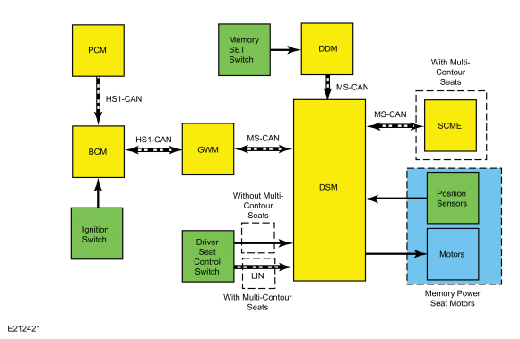
| Item | Description |
|---|---|
| 1 | Memory Power Seat Motors |
| 2 | HS1-CAN |
| 3 | PCM |
| 4 | HS1-CAN |
| 5 | Ignition Switch |
| 6 | GWM |
| 7 | Memory SET Switch |
| 8 | MS-CAN |
| 9 | DSM |
| 10 | MS-CAN |
| 11 | DDM |
| 12 | Position Sensors |
| 13 | Motors |
| 14 | LIN |
| 15 | With Multi-Contour Seats |
| 16 | Driver Seat Control Switch |
| 17 | BCM |
| 18 | Without Multi- Contour Seats |
| 19 | SCME |
| 20 | MS-CAN |
| 21 | With Multi- Contour Seats |
Network Message Chart - Memory Seat
DSM Network Input Messages
| Broadcast Message | Originating Module | Message Purpose |
|---|---|---|
| Key-in-ignition status | BCM | Provides the ignition status. This input is used for the easy entry/exit feature. |
| Personality recall | BCM | When the personality recall command is received from the BCM , the DSM stores or recalls the associated memory seat position (1, 2 or 3). If a RKE transmitter has been programmed to a memory position, this input is used to recall the associated memory seat position. |
| Memory seat switch status | DDM | When the memory set switch (1, 2 or 3) is activated, the DDM sends this message to the DSM , which then stores or recalls the associated memory seat position. |
SCMG Network Input Messages
| Broadcast Message | Originating Module | Message Purpose |
|---|---|---|
| Easy entry/exit | DSM | This input is used for the easy entry/exit feature. |
| Seat memory command | DSM | When the personality recall command is received from the DSM , the SCMG stores or recalls the associated memory seat bladder pressures and multi-contour adjust/massage setting for personality (1, 2 or 3). If a RKE transmitter has been programmed to a memory position, this input is used to recall the associated memory seat settings. |
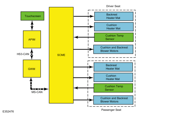
System Diagram - Heated Seats
*.sttxt { visibility: hidden; } *.stcallout { visibility: visible; } E348158 MS-CAN 1 GWM 2 Touchscreen 3 APIM HS3-CAN 6 Cushion Heater Mat 7 Cushion Temp Sensor 8 Backrest Heater Mat 9 HVAC Module 10 Cushion Temp Sensor 11 Cushion Heater Mat 12 Backrest Heater Mat| Item | Description |
|---|---|
| 1 | GWM |
| 2 | Touchscreen |
| 3 | APIM |
| 4 | Cushion Heater Mat |
| 5 | Cushion Heater Mat |
| 6 | Cushion Heater Mat Comment: Driver Seat |
| 7 | Cushion Temp Sensor Comment: Driver Seat |
| 8 | Backrest Heater Mat Comment: Driver Seat |
| 9 | HVAC Module |
| 10 | Cushion Temp Sensor Comment: Passenger Seat |
| 11 | Cushion Heater Mat Comment: Passenger Seat |
| 12 | Backrest Heater Mat Comment: Passenger Seat |
Network Message Chart - Heated Seats
HVAC Module Network Input Messages
| Broadcast Message | Originating Module | Message Purpose |
|---|---|---|
| Heated seat request | APIM | The heated seat request message allows the HVAC module to activate the heated seat(s) selected. |
APIM Network Input Messages
| Broadcast Message | Originating Module | Message Purpose |
|---|---|---|
| Heated seat request | HVAC Module | The HVAC module provides this message to the APIM for the purpose of updating the displayed status of the heated seat buttons on the touchscreen. |
System Diagram - Heated/Ventilated Seats
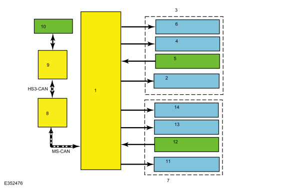
| Item | Description |
|---|---|
| 1 | SCME |
| 2 | Cushion and Backrest Blower Motors |
| 3 | Driver Seat |
| 4 | Cushion Heater Mat |
| 5 | Cushion Temp Sensor |
| 6 | Backrest Heater Mat |
| 7 | Passenger Seat |
| 8 | GWM |
| 9 | APIM |
| 10 | Touchscreen |
| 11 | Cushion and Backrest Blower Motors |
| 12 | Cushion Temp Sensor |
| 13 | Cushion Heater Mat |
| 14 | Backrest Heater Mat |
Network Message Chart - Heated/Ventilated Seats
SCME Network Input Messages
| Broadcast Message | Originating Module | Message Purpose |
|---|---|---|
| Climate control requests | APIM | The climate control requests message contains the climate controlled seat request information. |
APIM Network Input Messages
| Broadcast Message | Originating Module | Message Purpose |
|---|---|---|
| Climate control button status | SCME | The SCME provides this message to the APIM for the purpose of updating the displayed status of the heated/ventilated seat buttons on the APIM . |
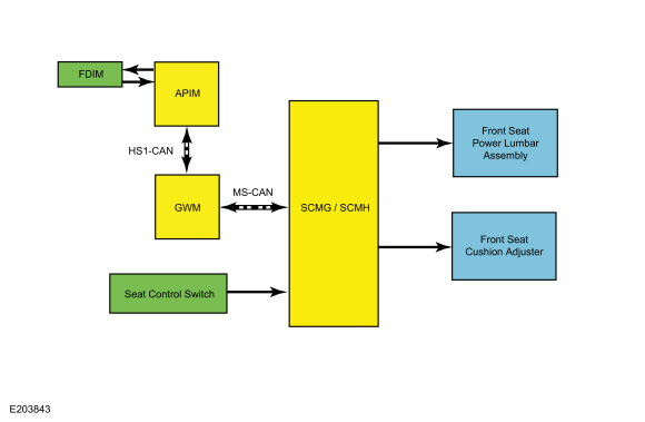
System Diagram - Multi-Contour Front Seats
.jpg)
| Item | Description |
|---|---|
| 1 | FDIM |
| 2 | APIM |
| 3 | HS3-CAN |
| 4 | GWM |
| 5 | MS-CAN |
| 6 | Seat Control Switch |
| 7 | SCMG / SCMH |
| 8 | Front Seat Power Lumbar Assembly |
| 9 | Front Seat Cushion Adjuster |
Network Message Chart - Multi-Contour Front Seats
FDIM Network Input Messages
| Broadcast Message | Originating Module | Message Purpose |
|---|---|---|
| Multi-contour seat switch status | SCMG / SCMH | The SCMG / SCMH provides this message to the FDIM for the purpose of updating the displayed status of the multi-contour seat buttons on the FDIM (touchscreen). |
| Driver/passenger multi-contour seat position data | SCMG / SCMH | The SCMG and SCMH provide this message to the FDIM for the purpose of updating the displayed pressure of the multi-contour seat bladders and bolster pairs on the FDIM (touchscreen). |
SCMG / SCMH Network Input Messages
| Broadcast Message | Originating Module | Message Purpose |
|---|---|---|
| Multi-contour seat request | FDIM | The multi-contour seat request message contains the requested multi-contour function(s) from the touchscreen. |
Memory Seat Operation
For vehicles without multi-contour seats, the driver seat control switch provides a voltage signal to the DSM when activated. If equipped with multi-contour seats, the driver seat control switch communicates over a LIN to the DSM . When the DSM receives the input from the seat control switch, the DSM provides power the appropriate seat motor until the input is removed. The motor circuits are normally grounded through the DSM . The DSM internally switches the appropriate circuit from ground to voltage to operate the motors.
As the seat is adjusted, the DSM monitors the motor position sensors to record the current seat position. The DSM removes voltage from the motor upon termination of the seat control switch input or if the DSM does not detect movement from the motor while monitoring the position sensor during a memory recall operation.
If the DSM loses the signal from any of the motor position sensors, the affected seat motor operates in jog mode. Jog mode allows limited operation of the affected seat motor using only the seat control switch. When the seat control switch is operated in jog mode, the seat moves in the desired direction for one second, then stops. The seat control switch must be released, then pressed again in order to move the seat for an additional second. Jog mode is an indication that there is a seat motor sensor fault.
DSM Hard Stop/Soft Stop
A hard stop occurs when one of the memory seat track or backrest axes physically reach the end of travel and can go no further. A soft stop occurs when the seat stops before it physically reaches the end of travel. The hard stop is set by seat design and cannot be changed or adjusted. The soft stop is set by the DSM . The seat track axes are forward/rearward, front up/down and rear up/down. The backrest axis is recline forward/backward. If equipped with multi-contour seats, there are additional axes for the cushion extension forward/rearward and head restraint forward/rearward and up/down. To prevent unnecessary stress on the seat and motors, the DSM sets soft stop positions, 2 for each moving axis. The DSM uses a preset distance from the hard stop to determine where the soft stop occurs. When an axis reaches the hard stop and the switch is held for approximately one second, the DSM briefly reverses direction and establishes the soft stop for that axis in that direction. The DSM uses this back up strategy to check sensor integrity any time movement has stopped prematurely due to a sensor failure or obstruction.
Easy Entry/Exit
The easy entry/exit feature is a function of the DSM that moves the driver seat back approximately 50.8 mm (2 in) (unless seat is already positioned at or near the end of travel) when the ignition is turned off. The DSM receives ignition off status over the MS-CAN and operates the driver seat rearward. The DSM cancels this operation if a valid input command is received from the driver seat control switch, memory set switch, exterior mirror control switch or if the function has been disabled.
The DSM records the current seat positions before operating the seat for an easy exit operation. During easy entry operation (when the ignition is turned on), the seat is returned to the recorded seat position prior to the easy exit operation. Easy entry operation is cancelled if a valid input command is received by the DSM . A memory position recall using the memory set switch also overrides the easy exit operation.
The easy entry/exit feature can be enabled/disabled on the message center. For information on programming vehicle settings in the message center, refer to the Owner's Literature.
Passenger Power Seat Operation
For vehicles without multi-contour seats, the seat control switches contain normally-closed contacts which are grounded. An individual circuit is switched to voltage when a specific adjustment position is selected. The seat control switches are hard-wired directly to the applicable seat motors. The motor direction is determined by the polarity of voltage supplied from the seat control switch.
If equipped with multi-contour seats, the passenger seat control switch communicates over a LIN to the SCMB . When the SCMB receives the input from the seat control switch, the SCMB provides power the appropriate seat motor until the input is removed. The motor circuits are normally grounded through the SCMB . The SCMB internally switches the appropriate circuit from ground to voltage to operate the motors.
If the SCMB loses the signal from any of the motor position sensors, the affected seat motor operates in jog mode. Jog mode allows limited operation of the affected seat motor using only the seat control switch. When the seat control switch is operated in jog mode, the seat moves in the desired direction for one second, then stops. The seat control switch must be released, then pressed again in order to move the seat for an additional second. Jog mode is an indication that there is a seat motor sensor fault. If the seat is operating in jog mode, a DTC sets in the SCMB .
Driver Power Head Restraint Operation
The power head restraint assembly contains a seat headrest motor (up/down) and a seat head restraint forward/rearward motor. The driver seat control switch communicates over a LIN to the DSM . When the DSM receives the input from the seat control switch, the DSM provides power the appropriate head restraint motor until the input is removed. The motor circuits are normally grounded through the DSM . The DSM internally switches the appropriate circuit from ground to voltage to operate the motors.
If the DSM loses the signal from any of the motor position sensors, the affected head restraint motor operates in jog mode. Jog mode allows limited operation of the affected head restraint motor using the seat control switch. When the seat control switch is operated in jog mode, the head restraint moves in the desired direction for one second, then stops. The seat control switch must be released, then pressed again in order to move the head restraint for an additional second. Jog mode is an indication that there is a head restraint motor sensor fault. If the head restraint is operating in jog mode, a DTC sets in the DSM .
As the driver seat head restraint is adjusted, the DSM monitors the motor position sensors to record the current seat position. The DSM removes voltage from the motor upon termination of the seat control switch input or if the DSM does not detect movement from the motor while monitoring the position sensor during a memory recall operation.
Passenger Power Head Restraint Operation
The power head restraint assembly contains a seat headrest motor (up/down) and a seat head restraint forward/rearward motor. The passenger seat control switch communicates over a LIN to the SCMB . When the SCMB receives the input from the seat control switch, the SCMB provides power the appropriate head restraint motor until the input is removed. The motor circuits are normally grounded through the SCMB . The SCMB internally switches the appropriate circuit from ground to voltage to operate the motors.
If the SCMB loses the signal from any of the motor position sensors, the affected seat motor operates in jog mode. Jog mode allows limited operation of the affected power head restraint motor using the seat control switch. When the seat control switch is operated in jog mode, the head restraint moves in the desired direction for one second, then stops. The seat control switch must be released, then pressed again in order to move the head restraint for an additional second. Jog mode is an indication that there is a head restraint motor sensor fault. If the head restraint is operating in jog mode, a DTC sets in the SCMB .
Heated Seat Operation
The driver and passenger heated seat buttons are selected from the touchscreen. The heated seat system functions independently of the vehicle's climate control system. Each time the heated seat button is pressed, the system decreases one setting (the sequence is high, med, low, off, high, etc.).
When activated, the HVAC module supplies voltage to the selected seat heater circuit. Each seat cushion heater mat and backrest heater mat is connected in a series circuit to the HVAC module and powered by the output circuit for that seat. The HVAC module monitors inputs from a temperature sensor located in each seat cushion heater mat, and maintains seat temperature by cycling the heater circuits on/off. The heated seat remains ON until the heated seat switch button is pressed to cycle the system OFF or the ignition is set to OFF.
If a fault is detected by the HVAC module, the module stops supplying voltage to that individual left or right seat that the fault was detected on until the ignition is turned OFF and then ON.
Heated/Ventilated Seat Operation
The driver and passenger heated/ventilated seat buttons are selected from the touchscreen. The heated/ventilated seat system functions independently from the vehicle's climate control system.
Heat Operation
- The system control settings are indicated next to each heated/ventilated seat switch button on the touchscreen. The first setting is HIGH (3 indicators), the second setting is MED (2 indicators) and the third is LOW (1 indicator) then OFF (no indicators).
- When activated, the SCME supplies voltage to the selected seat heater circuit. Each seat cushion heater mat and backrest heater mat is connected in a series circuit to the SCME and powered by the output circuit for that seat. The SCME monitors inputs from a temperature sensor located in each seat cushion heater mat, and maintains seat temperature by cycling the heater circuits on/off. The heated seat remains ON until the heated seat switch button is pressed to cycle the SCME OFF or the ignition is set to OFF.
Ventilation Operation
- The seat cushion and backrest are each equipped with a blower motor assembly. Each blower motor draws air through the surface of the cushion and backrest through the foam. Once the system is activated, the SCME controls the blower speed dependant on the heated/ventilated seat settings.
- The system control settings are based on the 3 indicators next to each heated/ventilated seat switch button on the touchscreen. The first setting is HIGH (3 indicators), the second setting is MED (2 indicators) and the third is LOW (1 indicator) then OFF (no indicators).
Remote Start Climate Operation
Different climate control modes/preferences can be selected when the vehicle is started using the remote start feature. This can be accessed through the message center. For additional information on how to set the remote start preferences, refer to the Owner's Literature. When the driver seat and/or passenger seat is set to AUTO mode, the driver/passenger heated seat activates in full heat mode when the outside temperature is less than 0° C (32° F) and full cool mode (heated/ventilated seats only) when outside temperature is greater than 27° C (80° F) any time the vehicle is started using the remote start feature. No heated/ventilated seat adjustments are recognized during remote start operation. Once the ignition is cycled ON, the heated/ventilated seat turns off.
Multi-Contour Seat Operation
The multi-contour seats are independently controlled by the seat control switches (located on the outer side of the front seat cushions) or the FDIM (touchscreen). The driver and passenger front seats each contain a total of 11 inflatable bladders: 4 cushion bladders, 2 cushion side bolsters, 3 backrest lumbar bladders and 2 backrest side bolsters. The pressures for the lumbar bladders, cushion bolster pair and backrest bolster pair are displayed on the FDIM as a percentage of the maximum pressure.
There are 2 modes of operation: adjust or massage. Adjust mode allows pressure changes in one of the 3 lumbar bladders and 2 sets of bolsters to be inflated or deflated to a desirable feel. Massage mode provides a sequence of inflation and deflation of the lumbar and cushion bladders to simulate a massage motion. When the massage mode is active, it will turn off (time-out) after 20 minutes of operation.
NOTE: Refer to the Owner's Literature for information how to select the various modes using the seat control switch or touchscreen buttons.
When in Adjust mode:
- Each tap of the up or down buttons cycles through the following bladders and bolsters: Upper lumbar, middle lumbar, lower lumbar, back bolster and cushion bolster.
- When the inflate/deflate buttons are pressed (or held), the pressure increases or decreases for the currently selected bladder or bolster pair.
- Pressing the mode select button toggles the seat to massage mode. The ignition must be on for massage mode to function.
When in Massage mode:
- Each tap of the up or down buttons cycles between backrest and cushion massage modes.
- Each tap of the inflate/deflate buttons cycles between the intensity levels of massage (off, low and high).
- Pressing the mode select button toggles the seat to adjust mode. Middle lumbar bladder will be selected automatically.
Each multi-contour seat can be restored to the original factory settings by pressing and holding the select button greater than 30 seconds. This resets all the adjust and massage settings (including any multi-contour driver seat settings associated to memory personality 1, 2 or 3).
Component Description
Seat Control Switch - Driver
For vehicles without multi-contour seats, the driver seat control switch is hard-wired to the DSM , which controls seat operation. The seat control switch contains normally closed contacts (which are grounded) through the DSM . When a specific adjustment position is selected, an individual circuit is switched to voltage.
If equipped with multi-contour seats, the driver seat control switch communicates seat commands over a LIN to the DSM , which controls seat movements. The driver seat control switch is hard-wired to the SCMG to control the multi-contour seat massage/adjust features. The driver seat control switch contains a 5 position momentary contact switch which provides an analog signal (stepped resistance) to the SCMG .
Seat Control Switch - Passenger
For vehicles without multi-contour seats, the seat control switches contain normally-closed contacts which are grounded. An individual circuit is switched to voltage when a specific adjustment position is selected. The seat control switches are hard-wired directly to the applicable seat motors.
If equipped with multi-contour seats, the passenger seat control switch communicates seat commands over a LIN to the SCMB , which controls seat movements. The passenger seat control switch is hard-wired to the SCMH to control the multi-contour seat massage/adjust features.The passenger seat control switch contains a 5 position momentary contact switch which provides an analog signal (stepped resistance) to the SCMH .
DSM
The driver seat power memory seat motors are hard-wired to the DSM . The DSM controls the operation of the power memory seat. The DSM communicates on the MS-CAN . The SCME is integral to the DSM . PMI is required on both the DSM and the SCME when a new DSM is installed. The DSM hard stop/soft stops must be set/reset any time a new DSM , driver seat track or driver seat backrest is installed.
SCMB
The passenger power seat motors are hard-wired to the SCMB . The SCMB controls the operation of the seat. The SCMB communicates on the MS-CAN . PMI is required on the SCMB when a new SCMB is installed.
Memory Set Switch
The memory set switch (part of the driver door lock switch assembly) contains 3 momentary contact switches. It is hard-wired to the DDM and is used to recall 1 of 3 memory positions stored in the DSM .
Driver Seat Track
There are 3 front seat track bi-directional motors present on power seat tracks. The horizontal (fore/aft) front seat track motor is the only seat track motor which can be serviced separately from the seat track assembly.
All other seat track motors (front height, rear height) are serviced as part of the seat track assembly. If equipped with multi-contour seats, there is also a seat cushion extension motor (fore/aft) which is also serviced as part of the seat track assembly.
Each seat track motor contains a Hall-effect sensor which provides seat track position information to the DSM for setting/obtaining desired preset seat memory positions. The seat track motors move the power seat forward/backward and up/down depending on the polarity of voltage supplied from the DSM .
Passenger Seat Track
The passenger power seat is equipped with 3 front seat track bi-directional motors. The horizontal (fore/aft) front seat track motor is the only seat track motor which can be serviced separately from the seat track assembly. If equipped with multi-contour seats, there is also a seat cushion extension motor (fore/aft) which is serviced as part of the seat track assembly. All other seat track motors (front height, rear height) are serviced as part of the seat track assembly.
Without multi-contour seats, the seat track motors move the power seat forward/backward and up/down depending on the polarity of voltage supplied from the seat control switch.
If equipped with multi-contour seats, the seat track motors move the power seat forward/backward and up/down depending on the polarity of voltage supplied from the SCMB . The seat track motors on vehicles equipped with multi-contour seats contain Hall-effect sensors which provides seat track position information to the SCMB for fault detection purposes only.
Driver Seat Backrest
The driver seat backrest contains a bi-directional motor which is integral to the seat backrest frame assembly. The seat backrest motor contains a Hall-effect sensor which provides seat backrest position information to the DSM for setting/obtaining desired preset seat memory positions. The seat backrest motor moves the seat backrest forward/backward depending on the polarity of voltage supplied from the DSM .
Passenger Seat Backrest
The passenger seat backrest contains a bi-directional motor which is integral to the seat backrest frame assembly. Without multi-contour seats, the seat backrest motor moves the seat backrest forward/backward depending on the polarity of voltage supplied from the seat control switch.
If equipped with multi-contour seats, the seat backrest motor contains a Hall-effect sensor which provides seat backrest position information to the SCMB for fault detection purposes only. The seat backrest motor moves the seat backrest forward/backward depending on the polarity of voltage supplied from the SCMB .
FDIM
The FDIM (touchscreen) contains the multi-contour seat control buttons (if equipped).
HVAC Module
If equipped with heated seats, when the heated seats are activated, the HVAC module monitors the seat cushion temperature sensor and supplies heater current to the seat cushion and backrest heater mats until the desired setpoint temperature is reached. Once the setpoint temperature is reached, the HVAC module cycles the heater circuits on/off as required to maintain the setpoint temperature. PMI is required when a new HVAC module is installed.
Heater Mat
The cushion heater mats are each equipped with a temperature sensor (thermistor) which provides feedback to the HVAC module (heated seats only) or SCME (heated/ventilated seats). The cushion and backrest heater mats are connected in series.
SCME
If equipped with heated/venitilated seats, the SCME controls the operation of the heated/ventilated seat system. The SCME is integral to the DSM . PMI is required for both the DSM and the SCME when a new DSM is installed.
SCMG
The SCMG controls the operation of the driver multi-contour seat. PMI is required when a new SCMG is installed. The SCMG communicates on the MS-CAN . The SCMG controls the air pump (part of the front seat power lumbar assembly) which supplies air pressure necessary to be diverted to the applicable air bladders/bolsters as required for the desired mode(s) of operation.
SCMH
The SCMH controls the operation of the passenger multi-contour seat. PMI is required when a new SCMH is installed. The SCMH communicates on the MS-CAN . The SCMH controls the air pump (part of the front seat power lumbar assembly) which supplies air pressure necessary to be diverted to the applicable air bladders/bolsters as required for the desired mode(s) of operation.
Blower Motor
If equipped with heated/ventilated seats, the seat cushion and backrest are each equipped with a blower motor assembly. The blower motor assembly is controlled by the SCME .
Front Seat Power Lumbar Assembly
The front seat power lumbar assembly is mounted to the backrest (serviced as an assembly).
Front Seat Power Lumbar Assembly - Multi-Contour Seats
The front seat power lumbar assembly includes an air pump, air hoses and bladders (serviced as an assembly).
Front Seat Cushion Adjuster - Multi-Contour Seats
The front seat cushion adjuster includes air hoses and bladders (serviced as an assembly).
Power Head Restraint Assembly
The front seat power head restraint assembly is mounted to the backrest (serviced as an assembly). The power head restraint assembly contains a seat headrest motor (up/down) and a seat head restraint forward/rearward motor.
 Front Seats - Overview. Description and Operation
Overview
Driver Power Seat
The power driver seat is controlled by the DSM . The DSM is located
on the driver seat track. The DSM hard stop/soft stops must be set/reset
any time a new DSM , driver seat track, horizontal motor or driver seat
backrest is installed...
 Front Seats. Diagnosis and Testing
DTC Chart: DDM
Diagnostics in this manual assume a certain skill level and knowledge of Ford-specific diagnostic practices. REFER to: Diagnostic Methods (100-00 General Information, Description and Operation)...
Other information:
Lincoln Nautilus 2018-2026 Service Manual: Vehicle Dynamics Control Module (VDM). Removal and Installation
Removal NOTICE: Electronic modules are sensitive to static electrical charges. If exposed to these charges, damage may result. NOTE: Removal steps in this procedure may contain installation details. Vehicles equipped with subwoofer Remove the subwoofer and amplifier unit...
Lincoln Nautilus 2018-2026 Service Manual: Rear Side Member Reinforcement Panel. Removal and Installation
Special Tool(s) / General Equipment 8 mm Drill Bit MIG/MAG Welding Equipment Spot Weld Drill Bit Locking Pliers Materials Name Specification Metal Bonding AdhesiveTA-1, TA-1-B, 3M™ 08115, LORD Fusor® 108B, Henkel Teroson EP 5055 - Removal NOTE: Left hand (LH) side shown, right hand (RH) side similar...
Categories
- Manuals Home
- 1st Generation Nautilus Owners Manual
- 1st Generation Nautilus Service Manual
- Opening and Closing the Hood
- Drive Mode Control
- Folding the Exterior Mirrors - Vehicles With: Manual Folding Mirrors. Folding the Exterior Mirrors - Vehicles With: Power Folding Mirrors
- New on site
- Most important about car
Auto-Start-Stop
What Is Auto-Start-Stop
The system is designed to help reduce fuel consumption and CO2 emissions by stopping the engine when it is idling, for example at traffic lights.
Auto-Start-Stop Precautions
WARNING: Apply the parking brake, shift into park (P), switch the ignition off and remove the key before you leave your vehicle. Failure to follow this instruction could result in personal injury or death.
WARNING: Apply the parking brake, shift into park (P), switch the ignition off and remove the key before you open the hood or have any service or repair work completed. If you do not switch the ignition off, the engine could restart at any time. Failure to follow this instruction could result in personal injury or d