Lincoln Nautilus: Front Suspension / Front Stabilizer Bar Bushing. Removal and Installation
Removal
NOTICE: Suspension fasteners are critical parts that affect the performance of vital components and systems. Failure of these fasteners may result in major service expense. Use the same or equivalent parts if replacement is necessary. Do not use a replacement part of lesser quality or substitute design. Tighten fasteners as specified.
NOTE: Removal steps in this procedure may contain installation details.
-
With the vehicle in NEUTRAL, position it on a hoist.
Refer to: Jacking and Lifting - Overview (100-02 Jacking and Lifting, Description and Operation).
-
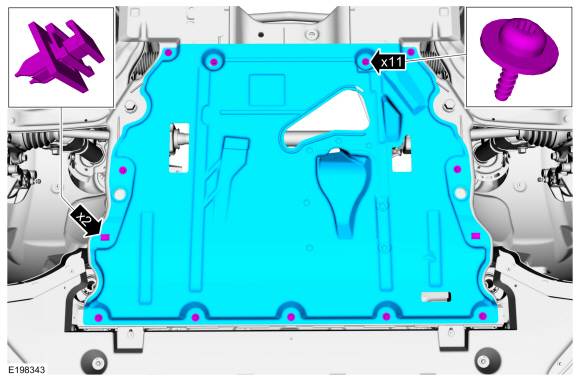
If equipped.
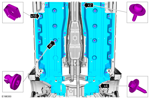
Remove the retainers and the under body shield.
 |
-
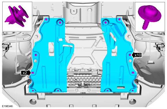
If equipped.
Remove the retainers and the dual under body shields.
 |
-
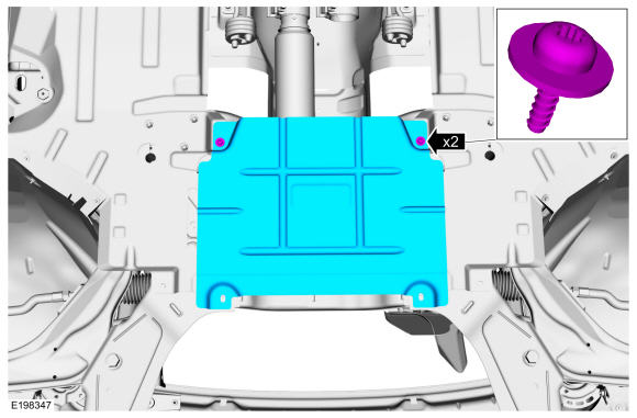
If equipped.
Remove the retainers and the center under body shield.
 |
-
If equipped.
Remove the retainers and the floor pan under body shields.
 |
-
On both sides.
-
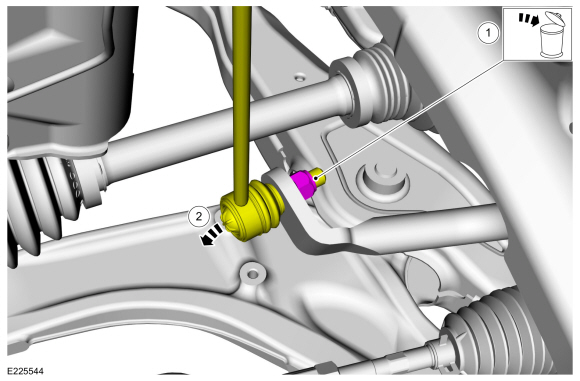
NOTE: The stabilizer bar links are designed with low friction ball joints that have a low breakaway torque.
NOTE: Use the hex-holding feature to prevent the ball stud from turning while removing or installing the stabilizer bar link nut.
Remove and discard the front stabilizer bar link lower nut.
Torque: 85 lb.ft (115 Nm)
-
Position the front stabilizer bar link aside.
-
 |
-
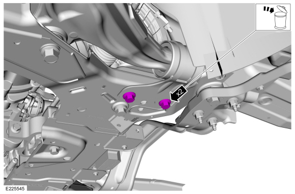
On both sides.
Remove and discard the front stabilizer bar bracket bolts.
Torque: 122 lb.ft (165 Nm)
 |
-
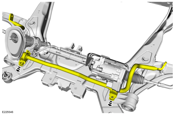
NOTE: The front stabilizer bar must be positioned towards the rear of the vehicle to gain access to the front stabilizer bar bushings.
Move the front stabilizer bar towards the rear of the vehicle.
 |
-
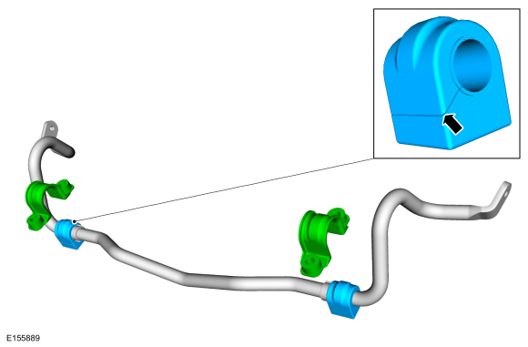
NOTICE: Do not use any lubrication on the stabilizer bar or the bushings or damage to the bushings may occur.
NOTE: Stabilizer bar bushings must be installed with slits facing the rear of the vehicle.
On both sides.
Remove the front stabilizer bar bushing brackets and the front stabilizer bar bushings.
 |
Installation
-
To install, reverse the removal procedure.
 Front Stabilizer Bar. Removal and Installation
Removal
NOTICE:
Suspension fasteners are critical parts that affect the
performance of vital components and systems. Failure of these fasteners
may result in major service expense...
 Front Stabilizer Bar Link. Removal and Installation
Removal
NOTE:
Removal steps in this procedure may contain installation details.
Remove the wheel and tire.
Refer to: Wheel and Tire (204-04A Wheels and Tires, Removal and Installation)...
Other information:
Lincoln Nautilus 2018-2026 Owners Manual: Auto Mode
Switching Auto Mode On and Off Press the button to switch auto mode on. Repeatedly press the button to adjust auto mode. The system adjusts the blower motor speed, air distribution, air conditioning operation, and outside or recirculated air to reach and maintain the temperature you have set...
Lincoln Nautilus 2018-2026 Service Manual: Instrument Panel Speaker. Removal and Installation
Special Tool(s) / General Equipment Interior Trim Remover Removal NOTE: Removal steps in this procedure may contain installation details. Release the clips and remove the instrument panel speaker grille. Use the General Equipment: Interior Trim Remover Remove the screws and position the instrument panel speaker up...
Categories
- Manuals Home
- 1st Generation Nautilus Owners Manual
- 1st Generation Nautilus Service Manual
- Replacing the Rear Wiper Blades
- Auto Hold
- Switching the Lane Keeping System On and Off. Switching the Lane Keeping System Mode
- New on site
- Most important about car
Opening and Closing the Hood
Opening the Hood