Lincoln Nautilus: Front Suspension / Front Strut and Spring Assembly. Removal and Installation
Removal
NOTICE:
Suspension fasteners are critical parts that affect the
performance of vital components and systems. Failure of these fasteners
may result in major service expense. Use the same or equivalent parts if
replacement is necessary. Do not use a replacement part of lesser
quality or substitute design. Tighten fasteners as specified.
-
Remove the wheel and tire.
Refer to: Wheel and Tire (204-04A Wheels and Tires, Removal and Installation).
-
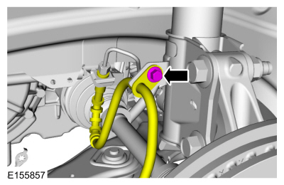
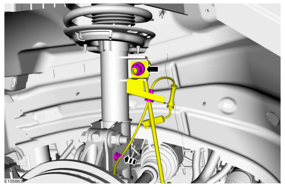
Remove the brake hose bracket bolt and position the brake hose aside.
-
-
If equipped.
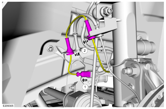
Disconnect the dynamic suspension electrical connector.
-
If equipped.
Unclip the dynamic suspension wire harness and position aside.
-
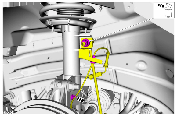
Remove and discard the front stabilizer bar link upper
nut and separate the front stabilizer bar link from the front strut and
spring assembly. Unclip and position aside the wheel speed sensor
harness.
-
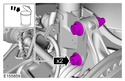
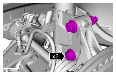
Remove and discard the front strut and spring assembly-to-wheel knuckle bolts and nuts.
-
Remove the cowl panel.
Refer to: Cowl Panel Grille (501-02)
.
-
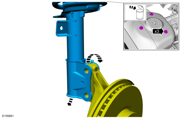
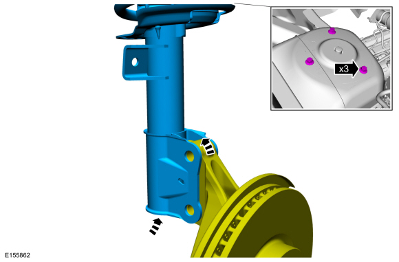
Remove and discard the front strut and spring assembly
upper bolts and remove the front strut and spring assembly from the
vehicle.
Installation
-
Position the front strut and spring assembly and install the new front strut and spring assembly upper bolts.
Torque:
26 lb.ft (35 Nm)
-
Install the cowl panel.
Refer to: Cowl Panel Grille (501-02)
.
-
Install the new front strut and spring assembly-to-wheel knuckle bolts and nuts.
Torque:
173 lb.ft (235 Nm)
-
Position the front stabilizer bar link and install the
new front stabilizer bar link upper nut. Position and clip the wheel
speed sensor harness.
Torque:
85 lb.ft (115 Nm)
-
-
If equipped.
Position dynamic suspension wire harness and clip the harness retainers in place.
-
If equipped.
Connect the dynamic suspension electrical connector.
-
Position the brake hose and install the brake hose bracket bolt.
Torque:
159 lb.in (18 Nm)
-
Install the wheel and tire.
Refer to: Wheel and Tire (204-04A Wheels and Tires, Removal and Installation).
-
Check and if necessary adjust front camber.
Refer to: Front Camber Adjustment (204-00 Suspension System - General Information, General Procedures).
-
Calibrate the suspension system. Connect the scan tool
and carry out the Ride Height Calibration routine. Follow the scan tool
directions.
Removal
NOTE:
Removal steps in this procedure may contain installation details.
Remove the wheel and tire.
Refer to: Wheel and Tire (204-04A Wheels and Tires, Removal and Installation)...
Special Tool(s) /
General Equipment
204-161
(T97P-1175-A)
Installer, HalfshaftTKIT-1997-LM2TKIT-1997-F/FM2TKIT-1997-FLM2
205-D070
(D93P-1175-B)
Remover, Front Wheel Hub
Removal
NOTICE:
Suspension fasteners are critical parts that affect the
performance of vital components and systems...
Other information:
What Is the Rear View Camera
The rear view camera provides a video
image of the area behind your vehicle when
the transmission is in reverse (R).
Rear View Camera Precautions
WARNING: The rear view camera
system is a reverse aid supplement device
that still requires the driver to use it in
conjunction with the interior and exterior
mirrors for maximum coverage...
System Operation
Roof Opening Panel Operating System
The accessory delay relay in the BCM
supplies voltage through fuse F31 (10A) to the roof opening panel
sliding glass motor and roof opening panel shield motor allowing the
motors to respond to roof opening panel control switch commands...

 Front Stabilizer Bar Link. Removal and Installation
 Front Wheel Bearing and Wheel Hub. Removal and Installation